Posts with «arduino» label

Play chess using voice commands and Arduino

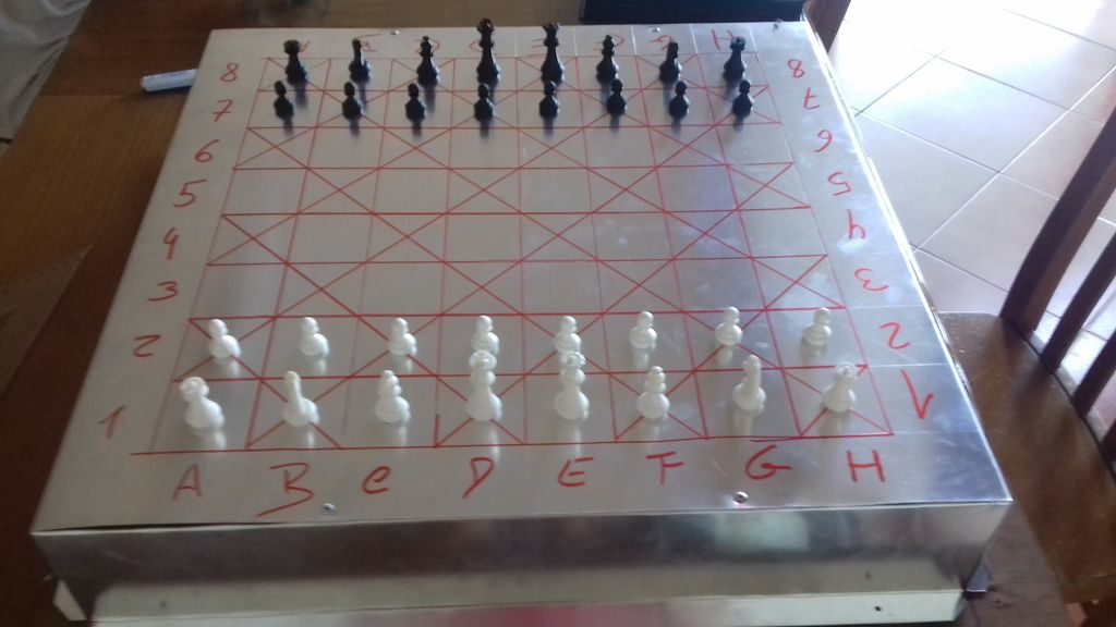
Consider the game of chess. It’s a game that flexes one’s “mental muscles” rather than relying on brute strength, but if you don’t have the ability to actually move the pieces, things get a bit more challenging. If you’re playing against another human opponent, he or she could move for you based on what you say, but with this chess machine by ‘diyguypt,’ the board does the job for you!

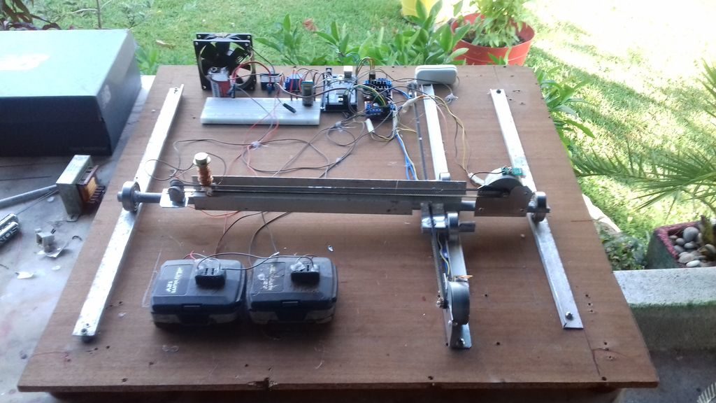
The system uses an Android-based Arduino Voice Control app to take in commands, and passes this information along to the Arduino Mega concealed under the board via an HC-05 Bluetooth module. It then controls a pair of stepper motors to move an electromagnet into place, which pull the pieces across the grid as if by magic! 

Code and build info are available in the project’s write-up, and the two videos below shed a little more light on how it works.

Voice Chess Uses Phone, Arduino, And An Electromagnet

[Diyguypt] may be an altruist to provide the means for people who can’t manipulate chess pieces to play the game. Or he may just have his hands too busy with food and drink to play. Either way, his voice command chessboard appears to work, although it has a lot of moving parts both figuratively and literally. You can check out the video below to see how it works.

The speech part is handled by an Android phone and uses Google’s voice services, so if you don’t want Google listening to your latest opening gambit, you’ll want to pass this one up. The phone uses an app that talks to the Arduino via Bluetooth, which means the Arduino needs a Bluetooth module.

The Arduino controls what amounts to an upside-down 3D printer. Instead of a hot end pointing down, the mechanism has an electromagnet pointing up. A small washer in the base of each chess piece makes it susceptible to the magnet’s motion. The electromagnet is required to let go of a piece before a move to a new position. It is possible that a small servo moving a permanent magnet closer to the board for a move and away from the board to reposition could do the same job, though we suspect that could be tricky.

We’ve seen this before, often with a Harry Potter theme. We sort of prefer a more obvious chess robot, but that’s just us.

Your Arduino SAMD21 ADC is Lying to You

One of the great things about the Arduino environment is that it covers a wide variety of hardware with a common interface. Importantly, this isn’t just about language, but also about abstracting away the gory details of the underlying silicon. The problem is, of course, that someone has to decode often cryptic datasheets to write that interface layer in the first place. In a recent blog post on omzlo.com, [Alain] explains how they found a bug in the Arduino SAMD21 analogRead() code which causes the output to be offset by between 25 mV and 57 mV. For a 12-bit ADC operating with a reference of 3.3 V, this represents a whopping error of up to 70 least-significant-bits!

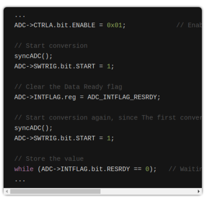
Excerpt from the SAMD wiring_analog.c file in the Arduino Core repo.

While developing a shield that interfaces to 24 V systems, the development team noticed that the ADC readings on a SAMD21-based board were off by a consistent 35 mV; expanding their tests to a number of different analog pins and SAMD21 boards, they saw offsets between 25 mV and 57 mV. It seems like this offset was a known issue; Arduino actually provides code to calibrate the ADC on SAMD boards, which will “fix” the problem with software gain and offset factors, although this can reduce the range of the ADC slightly. Still, having to correct for this level of error on a microcontroller ADC in 2019 — or even 2015 when the code was written — seems really wrong.

After writing their own ADC read routine that produced errors of only between 1 mV and 5 mV (1 to 6 LSB), the team turned their attention to the Arduino code. That code disables the ADC between measurements, and when it is re-enabled for each measurement, the first result needs to be discarded. It turns out that the Arduino code doesn’t wait for the first, garbage, result to finish before starting the next one. That is enough to cause the observed offset issue.

It seems odd to us that such a bug would go unnoticed for so long, but we’ve all seen stranger things happen. There are instructions on the blog page on how to quickly test this bug. We didn’t have a SAMD21-based Arduino available for testing before press time, but if you’ve got one handy and can replicate these experiments to verify the results, definitely let us know in the comments section below.

If you don’t have an Arduino board with a SAMD21 uC, you can find out more about them here.

Hack a Day 30 Aug 16:01

Arduino on mBed

Sometimes it seems like Arduino is everywhere. However, with a new glut of IoT processors, it must be quite a task to keep the Arduino core on all of them. Writing on the Arduino blog, [Martino Facchin], Arduino’s chief of firmware development, talks about the problem they faced supporting two new boards from Nordic.

The boards, the Nano 33 BLE and Nano 33 BLE Sense are based on an ARM Cortex M4 CPU from Nordic. The obvious answer, of course, is to port the Arduino core over from scratch. However, the team didn’t want to spend the time for just a couple of boards. They considered using the Nordic libraries to interact with the hardware, but since that is closed source, it didn’t really fit with Arduino’s sensitivities. However, in the end, they took a third approach which could be a very interesting development: they ported the Arduino core to the Mbed OS. There’s even an example of loading a sketch on top of Mbed available from [Jan Jongboom].

On the one hand, this has two big advantages: in theory, Arduino can now run on anything that supports Mbed, which is quite a lot. Second, even though the system retains the simplicity of Arduino, the entire Mbed system is available to Arduino developers and vice versa.

On the other hand, you could argue that if you have Mbed, you don’t really need Arduino. While much is made about Arduino’s simplicity, it is really a C++ program with two predefined functions and an IDE that builds your code without as much explicit help as you’d expect. However, the wide variety of code that supports Arduino should be of interest since you could just use it from either an Arduino or Mbed program without much effort.

This might make some of our favorite Mbed labs projects more popular. If you want to see our take on an Mbed project, you can turn it into a signal generator.

Thanks [halherta] for the tip.

Hack a Day 30 Aug 12:00
arduino  arduino hacks  arm  mbed  news  nordic  

Build your own Arduino-based delta robot with Delta X

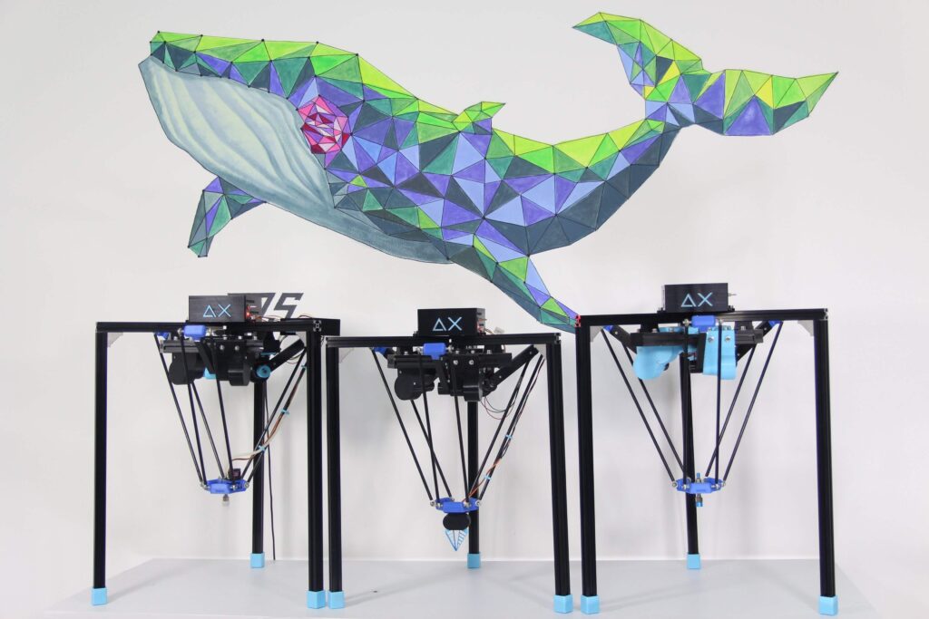
If you’ve ever seen a delta 3D printer work, you’ve certainly been amazed at the careful coordination of three motors to accurate position a carriage. While impressive in this role, delta robots can be used for much more, from laser engraving, to pick-and-place operations, to automated phone testing, or even playing the piano.

To make these systems a bit more accessible, Doan Hong Trung has developed an open source delta robot — dubbed Delta X — based on an Arduino Mega and a RAMPS 1.4 board that can do all of these jobs and more. 

Details on the modular kit are available here, along with many more clips of it in action. It’s slated to debut on Kickstarter soon, and you can sign up on deltaxrobot.com to be notified when it launches. Design files for the build will be released when successfully funded.

Arduino Blog 29 Aug 19:46

Steampunk radio and clock display with dual Arduino Mega control

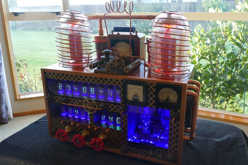
If you want to create your own steampunk/mad scientist entertainment center, it would be hard to top this radio/clock setup by Christine Thompson. 

Her device displays the time and date on eight VFD tubes, arranged on top of another eight that show the radio frequency and volume, along with the ambient temperature and pressure read by a BMP280 sensor.

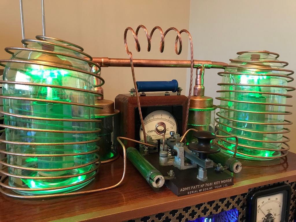
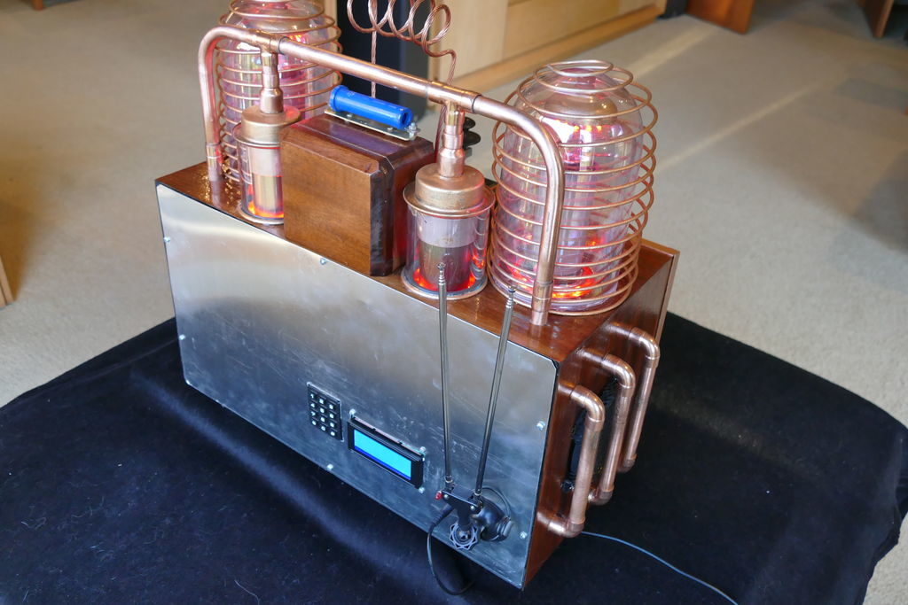
A wide variety of lighting effects, motor-driven clockwork, coils, and even an automated Morse key cement its steampunk theme, and it’s nicely housed in a restored radio cabinet. 

The project is controlled by a pair of Arduino Mega boards linked together via I2C, and Thompson’s write-up has all sorts of tidbits for potential retro-display builders.

This project is without doubt the most complex I have undertaken, with sixteen IV-11 VFD tubes, two Arduino Mega cards, ten LED Neon light circuits, a servo, an electromagnet, two MAX6921AWI IC Chips, five DC power supplies, a HV power supply, two DC Volt meters, a DC Amp meter, FM stereo radio, 3W power amplifier, LCD screen, and keyboard. Apart from the above parts list, two software programs had to developed from scratch and finally the construction of the entire radio required about 200 hours of work.

I decided to include this project onto the Instructables site not expecting members to reproduce this project in its entirety but rather to cherry pick the elements that where of interest to them. Two areas of particular interest to the site members may be the control of the 16 IV-11 VDF tubes using two MAX6921AWI chips and its associated wiring, and the communications between two Mega 2650 cards.

The various components included into this project have been sourced locally, except the IV-11 tubes, and the MAX6921AWI chips both obtained on EBay. I wanted to bring back to life various items that would otherwise languish in boxes for years. All of the HF valves where sourced with the understanding that all where failed units.

d.i.d. is a scalable 3D-printed pen plotter

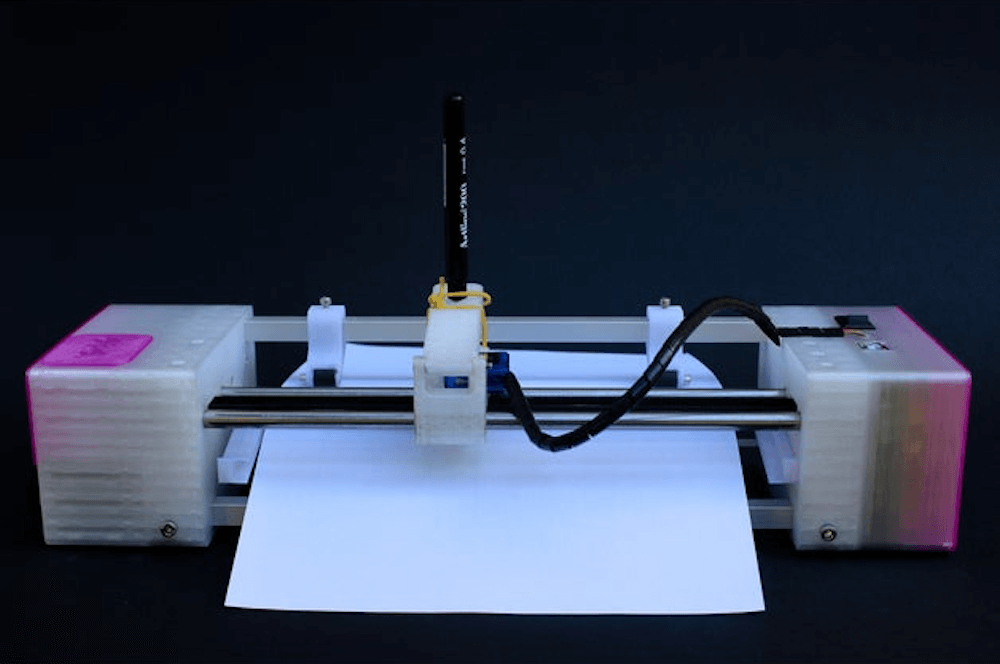
While computer printers are readily available, if you’d like a plotting device that drags a pen, marker, or whatever you need across paper to create images, your options are more limited. To fill this gap, studioprogettiperduti has come up with the d.i.d, or Deep Ink Diver.

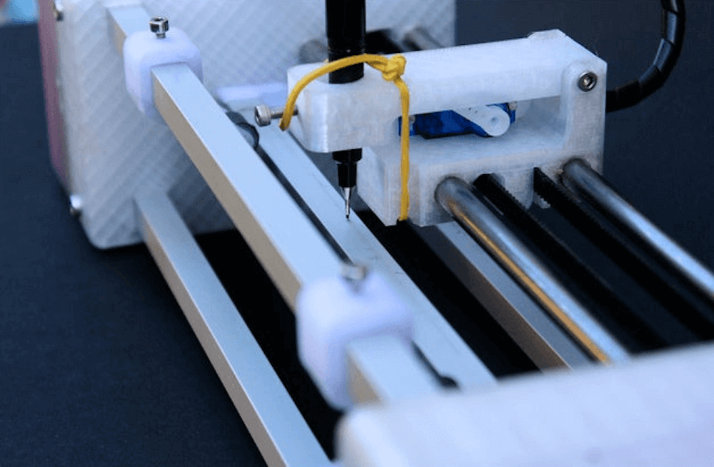
This scalable pen plotter uses a frame made out of 3D-printed parts, as well as aluminum extrusion, which could be lengthened to support the size of paper that you need. A timing belt pulls the writing carriage back and forth, while a roller advances the paper. 

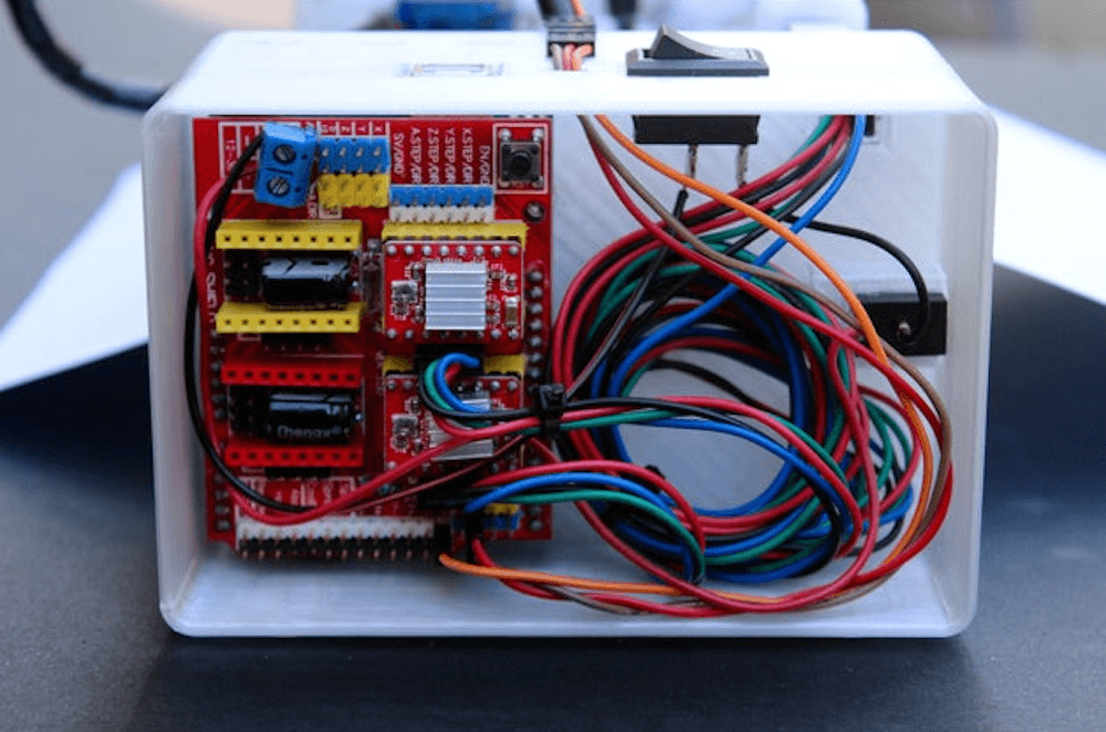
Control is handled by an Arduino Uno and a CNC shield, with a version of grbl that accommodates a servo used to lift the pen.

The materials and electronics used for the plotter are all standard and easy to source. The main frame is made of aluminum extrusion and 3D-printed connections. The motors are all standard NEMA 17 stepper motors and a single SG-90 servo motor. Everything is driven by a cheap Arduino Uno control board that handles the transition from g-code to movement. Furthermore, the software used to create G-code, Inkscape, is open source as well.

Tutorial – Using the 0.96″ 80 x 160 Full Color IPS LCD Module with Arduino

The purpose of this guide is to get your 0.96″ color LCD display successfully operating with your Arduino, so you can move forward and experiment and explore further types of operation with the display. This includes installing the Arduino library, making a succesful board connection and running a demonstration sketch.

Although you can use the display with an Arduino Uno or other boad with an ATmega328-series microcontroller – this isn’t recommended for especially large projects. The library eats up a fair amount of flash memory – around 60% in most cases.

So if you’re running larger projects we recommend using an Arduino Mega or Due-compatible board due to the increased amount of flash memory in their host microcontrollers.

Installing the Arduino library

So let’s get started. We’ll first install the Arduino library then move on to hardware connection and then operating the display.

(As the display uses the ST7735S controller IC, you may be tempted to use the default TFT library included with the Arduino IDE – however it isn’t that reliable. Instead, please follow the instructions below). 

First – download the special Arduino library for your display and save it into your Downloads or a temp folder.

Next – open the Arduino IDE and select the Sketch > Include Library > Add .ZIP library option as shown below:
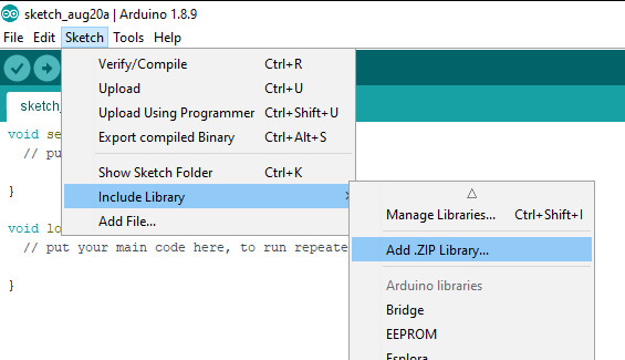
A dialog box will open – navigate to and select the zip file you downloaded earlier. After a moment or two the IDE will then install the library.

Please check that the library has been installed – to do this, select the Sketch > Include Library option in the IDE and scroll down the long menu until you see “ER-TFTM0.96-1” as shown below:

Once that has been successful, you can wire up your display.

Connecting the display to your Arduino

The display uses the SPI data bus for communication, and is a 3.3V board. You can use it with an Arduino or other 5V board as the logic is tolerant of higher voltages.

Arduino to Display

GND ----- GND (GND)
3.3V ---- Vcc (3.3V power supply)
D13 ----- SCL (SPI bus clock)
D11 ----- SDA (SPI bus data out from Arduino)
D10 ----- CS (SPI bus "Chip Select")
D9 ------ DC (Data instruction select pin)
D8 ------ RES (reset input)

If your Arduino has different pinouts than the Uno, locate the SPI pins for your board and modify as appropriate.

Demonstration sketch

Open a new sketch in the IDE, then copy and paste the following sketch into the IDE:

// https://pmdway.com/products/0-96-80-x-160-full-color-lcd-module
#include <UTFT.h>

// Declare which fonts we will be using
extern uint8_t SmallFont[];

// Initialize display
// Library only supports software SPI at this time
//NOTE: support  DUE , MEGA , UNO 
//SDI=11  SCL=13  /CS =10  /RST=8  D/C=9
UTFT myGLCD(ST7735S_4L_80160,11,13,10,8,9);    //LCD:  4Line  serial interface      SDI  SCL  /CS  /RST  D/C    NOTE:Only support  DUE   MEGA  UNO

// Declare which fonts we will be using
extern uint8_t BigFont[];

int color = 0;
word colorlist[] = {VGA_WHITE, VGA_BLACK, VGA_RED, VGA_BLUE, VGA_GREEN, VGA_FUCHSIA, VGA_YELLOW, VGA_AQUA};
int  bsize = 4;

void drawColorMarkerAndBrushSize(int col)
{
  myGLCD.setColor(VGA_BLACK);
  myGLCD.fillRect(25, 0, 31, 239);
  myGLCD.fillRect(myGLCD.getDisplayXSize()-31, 161, myGLCD.getDisplayXSize()-1, 191);
  myGLCD.setColor(VGA_WHITE);
  myGLCD.drawPixel(25, (col*30)+15);
  for (int i=1; i<7; i++)
    myGLCD.drawLine(25+i, ((col*30)+15)-i, 25+i, ((col*30)+15)+i);
  
  if (color==1)
    myGLCD.setColor(VGA_WHITE);
  else
    myGLCD.setColor(colorlist[col]);
  if (bsize==1)
    myGLCD.drawPixel(myGLCD.getDisplayXSize()-15, 177);
  else
    myGLCD.fillCircle(myGLCD.getDisplayXSize()-15, 177, bsize);
    
  myGLCD.setColor(colorlist[col]);
}
void setup()
{
  randomSeed(analogRead(0));
  
// Setup the LCD
  myGLCD.InitLCD();
  myGLCD.setFont(SmallFont);
}

void loop()
{
  int buf[158];
  int x, x2;
  int y, y2;
  int r;

// Clear the screen and draw the frame
  myGLCD.clrScr();

  myGLCD.setColor(255, 0, 0);
  myGLCD.fillRect(0, 0, 159, 13);
  myGLCD.setColor(64, 64, 64);
  myGLCD.fillRect(0, 114, 159, 127);
  myGLCD.setColor(255, 255, 255);
  myGLCD.setBackColor(255, 0, 0);
  myGLCD.print("pmdway.com.", CENTER, 1);
  myGLCD.setBackColor(64, 64, 64);
  myGLCD.setColor(255,255,0);
  myGLCD.print("pmdway.com", LEFT, 114);


  myGLCD.setColor(0, 0, 255);
  myGLCD.drawRect(0, 13, 159, 113);

// Draw crosshairs
  myGLCD.setColor(0, 0, 255);
  myGLCD.setBackColor(0, 0, 0);
  myGLCD.drawLine(79, 14, 79, 113);
  myGLCD.drawLine(1, 63, 158, 63);
  
 myGLCD.setColor(0, 0, 255);
 myGLCD.drawLine(0, 79, 159, 79);
 
  for (int i=9; i<150; i+=10)
    myGLCD.drawLine(i, 61, i, 65);
  for (int i=19; i<110; i+=10)
    myGLCD.drawLine(77, i, 81, i);
    

// Draw sin-, cos- and tan-lines  
  myGLCD.setColor(0,255,255);
  myGLCD.print("Sin", 5, 15);
  for (int i=1; i<158; i++)
  {
    myGLCD.drawPixel(i,63+(sin(((i*2.27)*3.14)/180)*40));
  }
  
  myGLCD.setColor(255,0,0);
  myGLCD.print("Cos", 5, 27);
  for (int i=1; i<158; i++)
  {
    myGLCD.drawPixel(i,63+(cos(((i*2.27)*3.14)/180)*40));
  }

  myGLCD.setColor(255,255,0);
  myGLCD.print("Tan", 5, 39);
  for (int i=1; i<158; i++)
  {
    myGLCD.drawPixel(i,63+(tan(((i*2.27)*3.14)/180)));
  }

  delay(2000);

  myGLCD.setColor(0,0,0);
  myGLCD.fillRect(1,14,158,113);
  myGLCD.setColor(0, 0, 255);
  myGLCD.setBackColor(0, 0, 0);
  myGLCD.drawLine(79, 14, 79, 113);
  myGLCD.drawLine(1, 63, 158, 63);

 myGLCD.setColor(0, 0, 255);
 myGLCD.drawLine(0, 79, 159, 79);  

// Draw a moving sinewave
  x=1;
  for (int i=1; i<(158*20); i++) 
  {
    x++;
    if (x==159)
      x=1;
    if (i>159)
    {
      if ((x==79)||(buf[x-1]==63))
        myGLCD.setColor(0,0,255);
      else
        myGLCD.setColor(0,0,0);
      myGLCD.drawPixel(x,buf[x-1]);
    }
    myGLCD.setColor(0,255,255);
    y=63+(sin(((i*2.5)*3.14)/180)*(40-(i / 100)));
    myGLCD.drawPixel(x,y);
    buf[x-1]=y;
  }

  delay(2000);
 
  myGLCD.setColor(0,0,0);
  myGLCD.fillRect(1,14,158,113);
  
 myGLCD.setColor(0, 0, 255);
 myGLCD.drawLine(0, 79, 159, 79);  

// Draw some filled rectangles
  for (int i=1; i<6; i++)
  {
    switch (i)
    {
      case 1:
        myGLCD.setColor(255,0,255);
        break;
      case 2:
        myGLCD.setColor(255,0,0);
        break;
      case 3:
        myGLCD.setColor(0,255,0);
        break;
      case 4:
        myGLCD.setColor(0,0,255);
        break;
      case 5:
        myGLCD.setColor(255,255,0);
        break;
    }
    myGLCD.fillRect(39+(i*10), 23+(i*10), 59+(i*10), 43+(i*10));
  }

  delay(2000);
  
  myGLCD.setColor(0,0,0);
  myGLCD.fillRect(1,14,158,113);
  myGLCD.setColor(0, 0, 255);
 myGLCD.drawLine(0, 79, 159, 79);   

// Draw some filled, rounded rectangles
  for (int i=1; i<6; i++)
  {
    switch (i)
    {
      case 1:
        myGLCD.setColor(255,0,255);
        break;
      case 2:
        myGLCD.setColor(255,0,0);
        break;
      case 3:
        myGLCD.setColor(0,255,0);
        break;
      case 4:
        myGLCD.setColor(0,0,255);
        break;
      case 5:
        myGLCD.setColor(255,255,0);
        break;
    }
    myGLCD.fillRoundRect(99-(i*10), 23+(i*10), 119-(i*10), 43+(i*10));
  }

  delay(2000);
  
  myGLCD.setColor(0,0,0);
  myGLCD.fillRect(1,14,158,113);

 myGLCD.setColor(0, 0, 255);
 myGLCD.drawLine(0, 79, 159, 79);  
// Draw some filled circles
  for (int i=1; i<6; i++)
  {
    switch (i)
    {
      case 1:
        myGLCD.setColor(255,0,255);
        break;
      case 2:
        myGLCD.setColor(255,0,0);
        break;
      case 3:
        myGLCD.setColor(0,255,0);
        break;
      case 4:
        myGLCD.setColor(0,0,255);
        break;
      case 5:
        myGLCD.setColor(255,255,0);
        break;
    }
    myGLCD.fillCircle(49+(i*10),33+(i*10), 15);
  }

  delay(2000);
    
  myGLCD.setColor(0,0,0);
  myGLCD.fillRect(1,14,158,113);
  
 myGLCD.setColor(0, 0, 255);
 myGLCD.drawLine(0, 79, 159, 79);    

// Draw some lines in a pattern
  myGLCD.setColor (255,0,0);
  for (int i=14; i<113; i+=5)
  {
    myGLCD.drawLine(1, i, (i*1.44)-10, 112);
  }
  myGLCD.setColor (255,0,0);
  for (int i=112; i>15; i-=5)
  {
    myGLCD.drawLine(158, i, (i*1.44)-12, 14);
  }
  myGLCD.setColor (0,255,255);
  for (int i=112; i>15; i-=5)
  {
    myGLCD.drawLine(1, i, 172-(i*1.44), 14);
  }
  myGLCD.setColor (0,255,255);
  for (int i=15; i<112; i+=5)
  {
    myGLCD.drawLine(158, i, 171-(i*1.44), 112);
  }

  delay(2000);
  
  myGLCD.setColor(0,0,0);
  myGLCD.fillRect(1,14,158,113);
  
 myGLCD.setColor(0, 0, 255);
 myGLCD.drawLine(0, 79, 159, 79);    

// Draw some random circles
  for (int i=0; i<100; i++)
  {
    myGLCD.setColor(random(255), random(255), random(255));
    x=22+random(116);
    y=35+random(57);
    r=random(20);
    myGLCD.drawCircle(x, y, r);
  }

  delay(2000);
  
  myGLCD.setColor(0,0,0);
  myGLCD.fillRect(1,14,158,113);
  
 myGLCD.setColor(0, 0, 255);
 myGLCD.drawLine(0, 79, 159, 79);    
  

// Draw some random rectangles
  for (int i=0; i<100; i++)
  {
    myGLCD.setColor(random(255), random(255), random(255));
    x=2+random(156);
    y=16+random(95);
    x2=2+random(156);
    y2=16+random(95);
    myGLCD.drawRect(x, y, x2, y2);
  }

  delay(2000);
  
  myGLCD.setColor(0,0,0);
  myGLCD.fillRect(1,14,158,113);
  
 myGLCD.setColor(0, 0, 255);
 myGLCD.drawLine(0, 79, 159, 79);    

// Draw some random rounded rectangles
  for (int i=0; i<100; i++)
  {
    myGLCD.setColor(random(255), random(255), random(255));
    x=2+random(156);
    y=16+random(95);
    x2=2+random(156);
    y2=16+random(95);
    myGLCD.drawRoundRect(x, y, x2, y2);
  }

  delay(2000);
  
  myGLCD.setColor(0,0,0);
  myGLCD.fillRect(1,14,158,113);
  
 myGLCD.setColor(0, 0, 255);
 myGLCD.drawLine(0, 79, 159, 79);  
 
  for (int i=0; i<100; i++)
  {
    myGLCD.setColor(random(255), random(255), random(255));
    x=2+random(156);
    y=16+random(95);
    x2=2+random(156);
    y2=16+random(95);
    myGLCD.drawLine(x, y, x2, y2);
  }

  delay(2000);
  
  myGLCD.setColor(0,0,0);
  myGLCD.fillRect(1,14,158,113);
  
 myGLCD.setColor(0, 0, 255);
 myGLCD.drawLine(0, 79, 159, 79);  
 
  for (int i=0; i<5000; i++)
  {
    myGLCD.setColor(random(255), random(255), random(255));
    myGLCD.drawPixel(2+random(156), 16+random(95));
  }

  delay(2000);

  myGLCD.fillScr(0, 0, 255);
  myGLCD.setColor(255, 0, 0);
  myGLCD.fillRoundRect(10, 17, 149, 72);
  
  myGLCD.setColor(255, 255, 255);
  myGLCD.setBackColor(255, 0, 0);
  myGLCD.print("That's it!", CENTER, 20);
  myGLCD.print("Restarting in a", CENTER, 45);
  myGLCD.print("few seconds...", CENTER, 57);
  
  myGLCD.setColor(0, 255, 0);
  myGLCD.setBackColor(0, 0, 255);
  myGLCD.print("Runtime: (msecs)", CENTER, 103);
  myGLCD.printNumI(millis(), CENTER, 115);

  delay (5000);   
}


Once you’re confident with the physical connection, upload the sketch. It should result with output as shown in the video below:

Now that you have succesfully run the demonstration sketch – where to from here?

The library used is based on the uTFT library by Henning Karlsen. You can find all the drawing and other commands in the user manual – so download the pdf and enjoy creating interesting displays.

This post brought to you by pmdway.com – everything for makers and electronics enthusiasts, with free delivery worldwide.

To keep up to date with new posts at tronixstuff.com, please subscribe to the mailing list in the box on the right, or follow us on twitter @tronixstuff.

Tronixstuff 29 Aug 09:15

Tutorial – Using the 0.96″ 128 x 64 Graphic I2C OLED Displays with Arduino

The purpose of this guide is to have an SSD1306-based OLED display successfully operating with your Arduino, so you can move forward and experiment and explore further types of operation with the display.

This includes installing the Arduino library, making a succesful board connection and running a demonstration sketch. So let’s get started!

Connecting the display to your Arduino

The display uses the I2C data bus for communication, and is a 5V and 3.3V-tolerant board.

Arduino Uno to Display

GND ---- GND (GND)
5V/3.3V- Vcc (power supply, can be 3.3V or 5V)
A5 ----- SCL (I2C bus clock)
A4 ----- SDA (I2C bus data)

I2C pinouts vary for other boards. Arduino Leonard uses D2/D3 for SDA and SCL or the separate pins to the left of D13. Arduino Mega uses D20/D21 for SDA and SCL. If you can’t find your I2C pins on other boards, ask your display supplier.

Installing the Arduino library

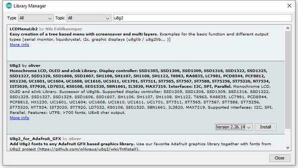
To install the library – simply open the Arduino IDE and select Manage Libraries… from the Tools menu. Enter “u8g2” in the search box, and after a moment it should appear in the results as shown in the image below. Click on the library then click “Install”:

After a moment the library will be installed and you can close that box.

Now it’s time to check everything necessary is working. Open a new sketch in the IDE, then copy and paste the following sketch into the IDE:

// Display > https://pmdway.com/products/0-96-128-64-graphic-oled-displays-i2c-or-spi-various-colors

#include <Arduino.h>
#include <U8x8lib.h>

#ifdef U8X8_HAVE_HW_SPI
#include <SPI.h>
#endif
#ifdef U8X8_HAVE_HW_I2C
#include <Wire.h>
#endif

  U8X8_SSD1306_128X64_NONAME_HW_I2C u8x8(/* reset=*/ U8X8_PIN_NONE);   

/*
  This example will probably not work with the SSD1606, because of the
  internal buffer swapping
*/

void setup(void)
{
  /* U8g2 Project: KS0108 Test Board */
  //pinMode(16, OUTPUT);
  //digitalWrite(16, 0);  

  /* U8g2 Project: Pax Instruments Shield: Enable Backlight */
  //pinMode(6, OUTPUT);
  //digitalWrite(6, 0); 

  u8x8.begin();
  //u8x8.setFlipMode(1);
}

void pre(void)
{
  u8x8.setFont(u8x8_font_amstrad_cpc_extended_f);    
  u8x8.clear();

  u8x8.inverse();
  u8x8.print(" U8x8 Library ");
  u8x8.setFont(u8x8_font_chroma48medium8_r);  
  u8x8.noInverse();
  u8x8.setCursor(0,1);
}

void draw_bar(uint8_t c, uint8_t is_inverse)
{ 
  uint8_t r;
  u8x8.setInverseFont(is_inverse);
  for( r = 0; r < u8x8.getRows(); r++ )
  {
    u8x8.setCursor(c, r);
    u8x8.print(" ");
  }
}

void draw_ascii_row(uint8_t r, int start)
{
  int a;
  uint8_t c;
  for( c = 0; c < u8x8.getCols(); c++ )
  {
    u8x8.setCursor(c,r);
    a = start + c;
    if ( a <= 255 )
      u8x8.write(a);
  }
}

void loop(void)
{
  int i;
  uint8_t c, r, d;
  pre();
  u8x8.print("github.com/");
  u8x8.setCursor(0,2);
  u8x8.print("olikraus/u8g2");
  delay(2000);
  u8x8.setCursor(0,3);
  u8x8.print("Tile size:");
  u8x8.print((int)u8x8.getCols());
  u8x8.print("x");
  u8x8.print((int)u8x8.getRows());
  
  delay(2000);
   
  pre();
  for( i = 19; i > 0; i-- )
  {
    u8x8.setCursor(3,2);
    u8x8.print(i);
    u8x8.print("  ");
    delay(150);
  }
  
  draw_bar(0, 1);
  for( c = 1; c < u8x8.getCols(); c++ )
  {
    draw_bar(c, 1);
    draw_bar(c-1, 0);
    delay(50);
  }
  draw_bar(u8x8.getCols()-1, 0);

  pre();
  u8x8.setFont(u8x8_font_amstrad_cpc_extended_f); 
  for( d = 0; d < 8; d ++ )
  {
    for( r = 1; r < u8x8.getRows(); r++ )
    {
      draw_ascii_row(r, (r-1+d)*u8x8.getCols() + 32);
    }
    delay(400);
  }

  draw_bar(u8x8.getCols()-1, 1);
  for( c = u8x8.getCols()-1; c > 0; c--)
  {
    draw_bar(c-1, 1);
    draw_bar(c, 0);
    delay(50);
  }
  draw_bar(0, 0);

  pre();
  u8x8.drawString(0, 2, "Small");
  u8x8.draw2x2String(0, 5, "Scale Up");
  delay(3000);

  pre();
  u8x8.drawString(0, 2, "Small");
  u8x8.setFont(u8x8_font_px437wyse700b_2x2_r);
  u8x8.drawString(0, 5, "2x2 Font");
  delay(3000);

  pre();
  u8x8.drawString(0, 1, "3x6 Font");
  u8x8.setFont(u8x8_font_inb33_3x6_n);
  for(i = 0; i < 100; i++ )
  {
    u8x8.setCursor(0, 2);
    u8x8.print(i);      // Arduino Print function
    delay(10);
  }
  for(i = 0; i < 100; i++ )
  {
    u8x8.drawString(0, 2, u8x8_u16toa(i, 5)); // U8g2 Build-In functions
    delay(10);    
  }

  pre();
  u8x8.drawString(0, 2, "Weather");
  u8x8.setFont(u8x8_font_open_iconic_weather_4x4);
  for(c = 0; c < 6; c++ )
  {
    u8x8.drawGlyph(0, 4, '@'+c);
    delay(300);
  }
  

  pre();
  u8x8.print("print \\n\n");
  delay(500);
  u8x8.println("println");
  delay(500);
  u8x8.println("done");
  delay(1500);

  pre();
  u8x8.fillDisplay();
  for( r = 0; r < u8x8.getRows(); r++ )
  {
    u8x8.clearLine(r);
    delay(100);
  }
  delay(1000);
}

Your display should go through the demonstration of various things as shown in the video below:

If the display did not work – you may need to manually set the I2C bus address. To do this, wire up your OLED then run this sketch (open the serial monitor for results). It’s an I2C scanner tool that will return the I2C bus display. 

Then use the following line in void setup():

u8x8.setI2CAddress(address)

Replace u8x8 with your display reference, and address with the I2C bus address (for example. 0x17).

Moving on…

By now you have an idea of what is possible with these great-value displays.

Now your display is connected and working, it’s time to delve deeper into the library and the various modes of operations. There are three, and they are described in the library documentation – click here to review them

Whenever you use one of the three modes mentioned above, you need to use one of the following constructor lines:

U8G2_SSD1306_128X64_NONAME_F_HW_I2C u8g2(U8G2_R0, /* reset=*/ U8X8_PIN_NONE); // full buffer mode

U8X8_SSD1306_128X64_NONAME_HW_I2C u8x8(/* reset=*/ U8X8_PIN_NONE); // 8x8 character mode

U8G2_SSD1306_128X64_NONAME_1_HW_I2C u8g2(U8G2_R0, /* reset=*/ U8X8_PIN_NONE); // page buffer mode

Match the mode you wish to use with one of the constructors above. For example, in the demonstration sketch you ran earlier, we used the 8×8 character mode constructor in line 14.

Where to from here?

Now it’s time for you to explore the library reference guide which explains all the various functions available to create text and graphics on the display, as well as the fonts and so on. These can all be found on the right-hand side of the driver wiki page.

This post brought to you by pmdway.com – everything for makers and electronics enthusiasts, with free delivery worldwide.

To keep up to date with new posts at tronixstuff.com, please subscribe to the mailing list in the box on the right, or follow us on twitter @tronixstuff.

Tronixstuff 29 Aug 08:38

Desktop USB drum for some serious finger tapping

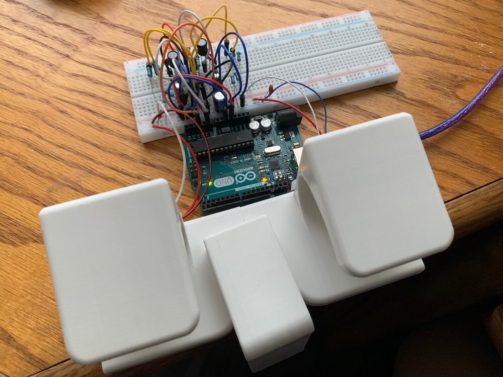
When you need a distraction, or perhaps even now, you may turn to tapping on your desk. While a good way to keep your hands active, or pass a few uninteresting seconds, if you want to get serious with your finger drumming, then the “Arduino USB Drum” by creator colonelwatch may be just the thing.

The 3D-printable device hooks onto the edge of the table, and reads taps on its pads with a pair of strain gauges. Signals are amplified and passed along to an Arduino Uno—including tap intensity—which sends MIDI data to a computer via serial. 

Code and other build info are available on GitHub, and you can see a video of it in action here.