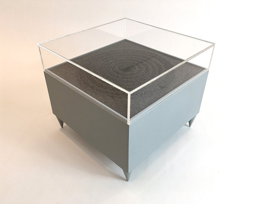
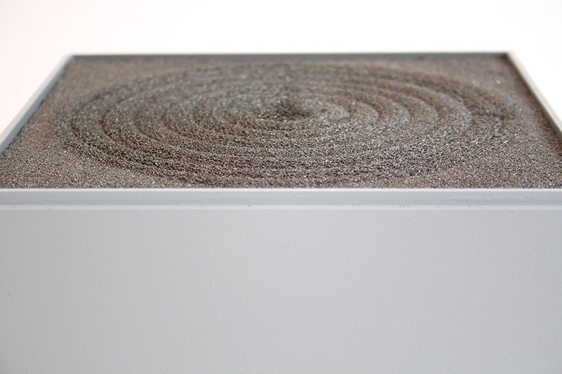
Artist Jo Fairfax has created automated drawing machines inspired by carefully manicured Japanese rock gardens, AKA zen gardens. The mesmerizing artwork uses magnets and motors that move underneath a bed of iron filings, generating soothing shapes as viewers come near via motion sensor.
An Arduino Uno is utilized for the device, or rather devices, and you can see a square “magnet garden” in the first video below, automatically producing a circular pattern. A (non-square) rectangular garden sketches a sort of snake/wave pattern in the second clip.
The build is reminiscent of sand drawing machines that rotate a metal marble through magnetic force, but does away with a visible source of movement as the filings react directly to the magnetic field as it’s applied.
An Arduino Uno is programmed to set off a mechanism with integrated magnets below the platform of iron filings. each time a viewer approaches the machine, it starts to ‘draw’ and agitate the black particles, moving them around the platforms. Slowly the drawings become three dimensional and the sense of the magnets’ tracing becomes visible.
The charged iron filings create varying geometric clusters that shape the zen gardens. The drawing machines reveal the forces acting on them, imitating grass and sand that react to the natural force of the wind. the gesture of the viewer’s movement that activates the machine coupled with the magnetic power makes the artwork become a dialogue of forces… elegant and subtle, just like a zen garden.
This post is from Sandeep Mistry, Senior Software Engineer at Arduino.
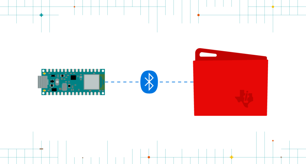
Today, we are pleased to announce BLE (Bluetooth Low Energy) central support in v1.1.0 of the ArduinoBLE library. This major feature addition allows your Arduino board to scan for and connect to BLE peripheral devices. With one simple library, you can now use BLE to directly connect your Arduino board to:
A smartphone, tablet, laptop or PC
BLE peripherals (e.g. TI SensorTag) – NEW!
Another Arduino board – NEW!
The ArduinoBLE library and new BLE central feature are supported on the following Arduino boards:
Prior to this release, Arduino only officially supported BLE peripheral functionality on these boards. A BLE peripheral is typically used to expose some sensor data or actuators to another device BLE central capable device such as a smartphone or PC. With the new BLE central functionality, you’ll be able to wirelessly connect two boards together for communication or connect to a third party BLE peripheral, such as a TI SensorTag.
We think that the ArduinoBLE library is much easier to use than anything else out there and are excited to see what you build with this new capability!
The development journey
Back in 2015, the Arduino 101 was released, based on the Curie module developed by Intel. It was the first official Arduino board with on-board BLE support. The CurieBLE library initially only supported BLE peripheral mode.
After launch, the Arduino and Intel teams worked together to design an Arduino friendly BLE API that supported both BLE Peripheral and Central functionality. This was released later in 2016 in the v2.0 of the Arduino core for Arduino 101.
The BLE features of the 101 were also incorporated into the CTC 101 kit in many classrooms around the world. Students used smartphones or tablets for exercises in the kit to interact with project based lessons running on the board. Unfortunately, Intel decided to stop producing the Curie module in 2017, bringing the Arduino 101 board to end of life.
Last year, at Maker Faire Bay Area 2018, Arduino launched two new boards: the MKR WiFi 1010 and Uno WiFi Rev.2. Both boards use the u-blox NINA-W102 as a 2.4 GHz wireless module. Initially both boards only supported WiFi using the WiFiNINA library. However, the ESP32 chip inside the u-blox NINA-W102 supports Bluetooth classic and BLE as well.
Later in 2018, the Arduino core team was tasked with adding BLE support to the MKR WiFi 1010 board so that it could be used with the upcoming Arduino Science Kit Physics Lab product. The Science Kit Physics Lab product is another educational kit, targeted for students in the classroom. We had several choices to move forward, including:
Bridging the ESP-IDF’s BLE API’s via RPC to the main MCU that sketches run on
Basing things on the industry standard Bluetooth HCI protocol and investing in a Bluetooth HCI host stack as an Arduino library
The first option above was expected to take an equal amount of time to the second, but also would make the BLE library exposed to users highly dependent on the underlying firmware running on the ESP32. It was also not as portable to other chip sets in the future. Thus, ArduinoBLE was created. The NINA firmware only needed small change to bridge its virtual Bluetooth HCI controller to the UART pins of the module.
Earlier this year, we released the Arduino Nano 33 IoT and Arduino Nano 33 BLE boards. Since the Arduino Nano 33 IoT uses the same chipset as the MKR WiFi 1010, things worked out of the box. For the Nano 33 BLE, which is based on the Nordic nRF52840 chip, a new Arduino core was developed for this board based on mbed OS (see this blog post for more info). mbed OS includes a radio stack called Cordio, which provides both a Bluetooth HCI link controller and HCI host. Creating a single C++ class that interfaced with Cordio’s Bluetooth HCI link layer allowed us to re-use 95%+ of ArduinoBLE on this board.
After the Nano 33 BLE started shipping, there was even more demand for BLE central support. So, development for feature was scheduled and is now available. It combines the API designed for the Arduino 101 in CurieBLE ported on top of ArduinoBLE’s Bluetooth HCI host stack.
Many thanks to Tom Igoe, one of the co-founders of Arduino, for providing feedback on the official Arduino BLE libraries throughout the years.
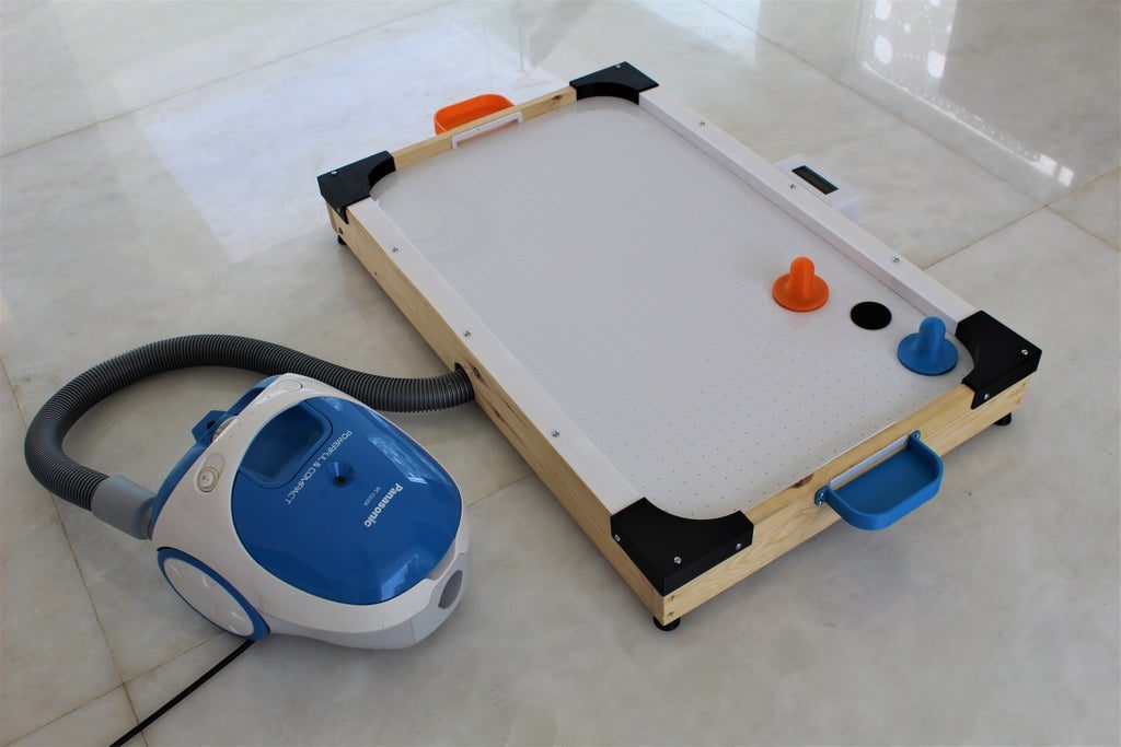
Cleverly, the scaled-down game table uses a household vacuum cleaner blower attachment to provide air pressure, sending little jets of air through a grid of laser-cut holes on the acrylic playing surface.
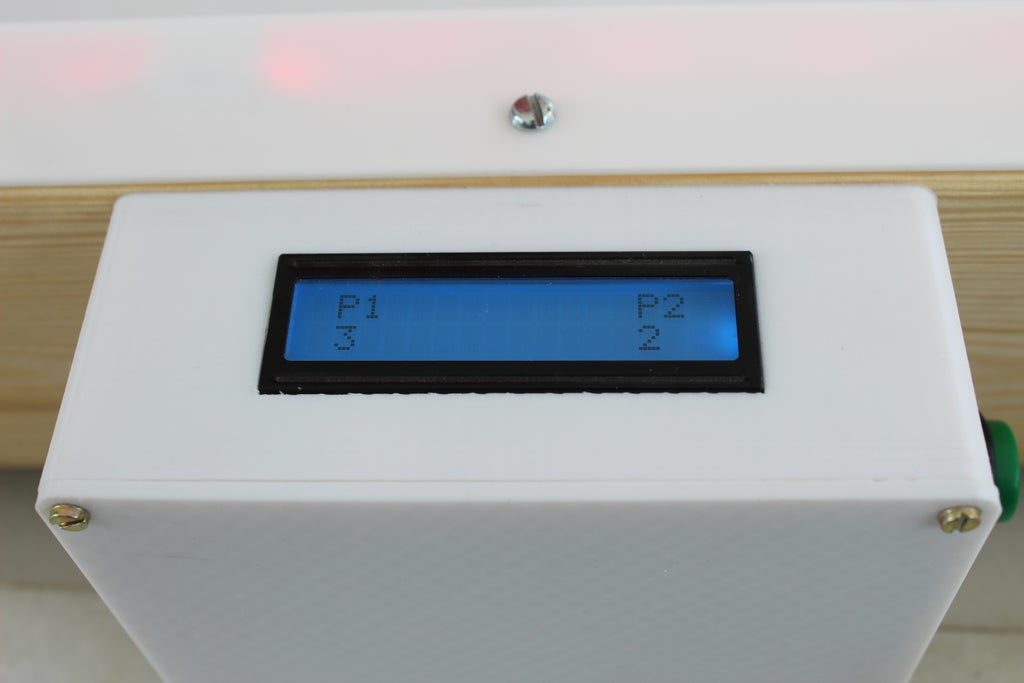
LED lights embedded in the sides add a bit more excitement to the build, and points are tallied with an Arduino Uno-based LCD score display. A pair of buttons are used to register a points for either player, hopefully eliminating arguments over who is ahead as the game progresses!
Many of us have considered buying an air hockey table, but are put off by the price. And even if the money is there, those things take up a lot of space. How often are you really going to use it?
This DIY air hockey table is the answer. It’s big enough to be fun, but small and light enough to easily stow away in the off-season. At ~$50, it’s a cheap build, provided you have a vacuum cleaner that can switch to blower mode. The strikers, goals, corner guards, and scoreboard enclosure are all 3D-printed, while the pucks and playfield are laser-cut acrylic. [Technovation] glued acrylic feet to the strikers to help them last longer.
The scoreboard is an Arduino Uno plus an LCD that changes color to match the current winner. Scoring must be entered manually with button presses, but we think it would be fairly easy to detect a puck in the goal with a force or weight sensor or something. For now, the RGB LEDs around the edge are controlled separately with a remote. The ultimate goal is to make the Arduino do it. Shoot past the break and cross-check it out.
We’ve all seen those chess computers that consist out of a physical playing field, and a built-in computer that would indicate where you should put its pieces while inputting the position of your pieces in some way. These systems are usually found in a dusty cardboard box in a back room’s closet, as playing like this is fairly cumbersome, and a lot depends on the built-in chess computer.
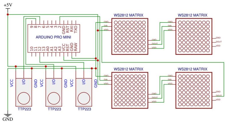
This take by [andrei.erdei] on this decades-old concept involves an ATmega328p-based Arduino Pro Mini board, a nice wooden frame, and 4 WS2812-based 65×65 mm RGB 8×8 LED matrices, as well as some TTP223 touch sensors that allow one to control the on-board cursor. This is the sole form of input: using the UP and RIGHT buttons to select the piece to move, confirm with OK, then move to the new position. The chess program will then calculate its next position and indicate it on the LED matrix.
Using physical chess pieces isn’t required either: each 4×4 grid uses a special pattern that indicates the piece that occupies it. This makes it highly portable, but perhaps not as fun as using physical pieces. It also kills the sheer joy of building up that collection of enemy pieces when you’ve hit that winning streak. You can look at the embedded gameplay video after the break and judge for yourself.
At the core of the chess program is [H.G. Muller]’s micro-Max project. Originally ported to the Arduino Uno, this program outputs the game to the serial port. After tweaking it to use the LED matrix instead, [andrei.erdei] was then faced with the lack of memory on the board for the most common LED libraries. In the end, the FAB_LED library managed to perform the task with less memory, allowing it and the rest of the program to fit comfortably into the glorious 2 kB of SRAM that the ATmega328p provides.
Classic 8-bit chess engines are marvels of software engineering. Ever wonder how they stack up against modern chess software? Check out this article!
Ah, the joys of domestic animals. Often adorable, occasionally useful, they’re universally unable to care for themselves in the slightest. That’s part of the bargain though; we take over responsibility for their upkeep and they repay us with whatever it is they do best. Unless the animal in question is a cat, of course – they have their own terms and conditions.
Chickens, though, are very useful indeed. Give them food and water and they give you delicious, nutritious, high-quality protein. Feeding them every day can be a chore, though, unless you automate the task. This Twitch-enabled robotic chicken feeder may be overkill for that simple use case, but as [Sean Hodgins] tell it, there’s a method to all the hardware he threw at this build. That would include a custom-welded steel frame holding a solar panel and batteries, a huge LED matrix display, a Raspberry Pi and camera, and of course, food dispensers. Those are of the kind once used to dispense candy or gum for a coin or two in the grocery; retooled with 3D-printed parts, the dispensers now eject a small scoop of feed whenever someone watching a Twitch stream decides to donate to the farm that’s hosting the system. You can see the build below in detail, or just pop over to Sweet Farm to check out the live feed and gawk at some chickens.
It’s an impressive bit of work on [Sean]’s part for sure, and we did notice how he used his HCC rapid prototyping module to speed up development. Still, we’re not convinced there will be many donations at $10 a pop. Then again, dropping donations to the micropayment level may lead to overfed chickens, and that’s not a good thing.
A few weeks ago, we announced that Arduino now works with TinyGo, the popular compiler that brings the Go programming language to microcontrollers. We had the opportunity to sit down with Ron Evans, Technologist for Hire, and learn more about the Arduino and TinyGo integration.
Some of our audience knows about Go (we ourselves use it to develop many of our tools). In a few words: what is TinyGo and how does it stand compared to Go itself?
TinyGo is a Go compiler for small places like microcontrollers. TinyGo is written in Go like the standard Go compiler, but TinyGo then uses the LLVM toolchain to compile Go programs to a fraction of their normal size. TinyGo also employs a different runtime implementation in order to target constrained environments.
Why choosing TinyGo over other languages?
If software is eating the world, then Go is eating the world of software. The popularity of Go is still rapidly expanding, and TinyGo helps bring the new “enterprise standard” language down to the smallest of processors. Also as a compiled language, TinyGo can offer substantially better performance and size efficiency than that of interpreted languages like JavaScript and Python.
How does TinyGo compare to embedded python and JavaScript implementations?
One good reason to use Go is the clear and maintainable code that Go insists that you create. Generally speaking, the normal Go tooling that is included with the language itself is what you use when writing TinyGo code. For example, the standard built-in code formatting. TinyGo includes implementations of the Go “net” package targeting the Arduino Nano33 IoT, so you can more easily reuse existing Go code for TCP/UDP or higher level protocols such as MQTT. This really makes it a lot easier to build commercial or industrial IoT solutions.
Another reason to use TinyGo is the ability to utilize Go’s concurrency. TinyGo implements “goroutines” which can greatly simplify your code to take the greatest performance advantage offered by modern 32-bit microcontrollers.
With security in IoT being one of today’s hottest topics, which tools does TinyGo offer that enable the development of secure projects?
There are a number of things that can make development, deployment, and operations using TinyGo good for edge computing applications that require greater security. Since the code is compiled to binary, it is possible to use code signing and other well known approaches for secure computing.
Another is that any device data must be encrypted while in transit from from the device to any cloud storage or analytics. TinyGo on the Arduino Nano33 IoT can use standard APIs for SSL communication to cloud services, such as using the Eclipse Foundation’s Paho MQTT client for Go. This makes it a lot easier for developers to do the right thing the first time when creating applications.
How can TinyGo improve the Arduino ecosystem? How will our existing audience benefit from using it? Will they be able to use the Arduino libraries already existing?
There is a very active community in the Arduino world, with lots of existing useful libraries. We are planning much deeper integration for TinyGo powered by Arduino, more on this in the near future…
Many people love TinyGo because it’s simple yet powerful. Do you see any similarity with the Arduino mission of ‘making technology simple for everybody?'”
Arduino has really pioneered the open hardware movement, and defining clear APIs to devices has been a huge contribution. TinyGo very much tries to embody this same spirit, while at the same time provide an idiomatic Go language programming experience. Combine the sensibilities that have made TinyGo so popular and that are fueling our continuing growth, alongside the amazing capabilities powered by Arduino, and there are no limits to what we can do!
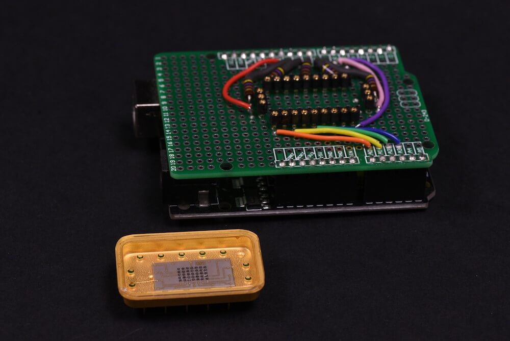
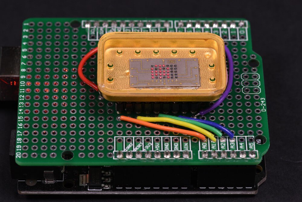
Patrick Hickey has been collecting retro LED indicators and displays for decades, and his rarest item is an HP 5082-7002—a 5×7 dot matrix LED display in a beautiful gold and (possibly) sapphire enclosure. This device is so rare, in fact, that he believes it to be a prototype, somehow relegated to eBay for gold salvage.
Hickey wasn’t able to find any reference to the unit—much less a datasheet—even after extensive research. Instead, he went to work reverse engineering the HP 5082-7002 following the tracks of the PCB to work out how the rows and columns are connected.
He then designed a test shield for an Arduino Uno with sockets on which the mystery device could sit. With this piece of hardware built, he can now create simple pictures and animated sprites on it using pulsed Arduino outputs.
I followed the tracks to work out which pins are connected rows and columns, and set out to build a test shield for an Arduino Uno. I decided to drive them as “rows” of 5. The max output of Arduino I/O pins is rated at 40mA, so in theory, I could simultaneously power up to 5 LEDs in parallel at 8mA using 1 pin. In practice, using strobe/multiplexing, the duty cycle is much less: 1/7 or 1/5 depending if you drive by rows (7) or columns (5) respectively. The 5 current limiting series resistors are 470 Ohms (¼ Watt). My preference is to use carbon composition resistors (e.g. Allen Bradley). I love the “retro look” of them and I think they compliment the vintage LEDs.
I had already written Arduino code for testing some TIL-305 matrix displays, so it was relatively simple to transpose the pins in my sketch for this configuration. The test code permits animations of up to 150 different alphanumeric characters/symbols, and (of course) some animated sprites inspired by retro video games.
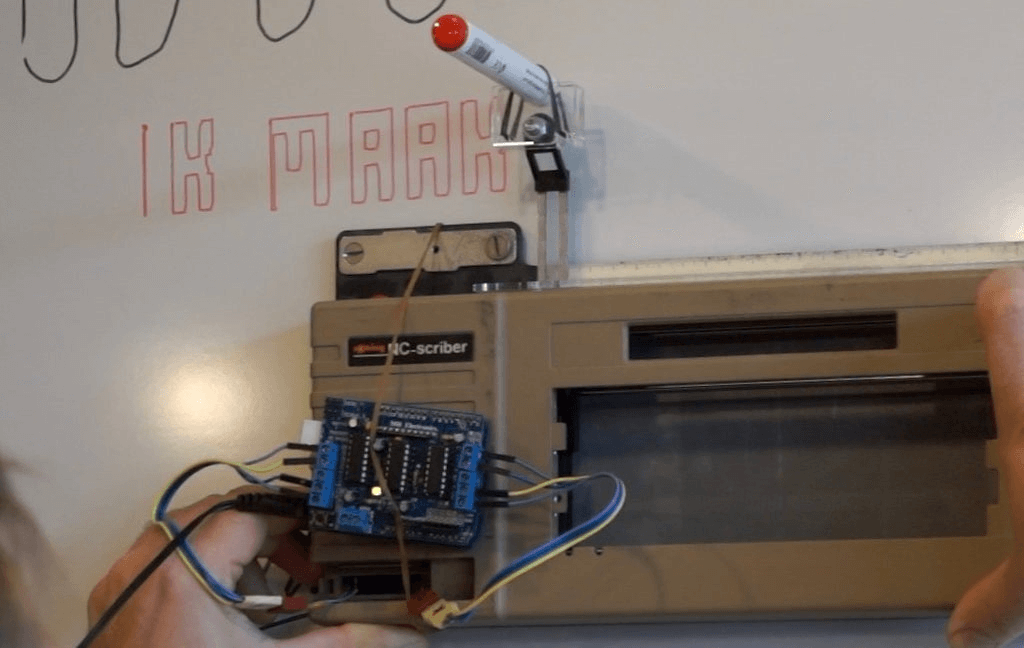
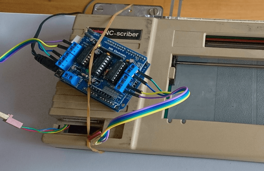
Writing on a whiteboard isn’t an easy task for many people, including instructor ‘Kenyer,’ whose lettering can be on display for a semester or more. Rather than accept his imperfect penmanship, he modified a 1980s-era Rotring NC-Scriber—originally meant for mechanical drawing use—to do this for him.
His project runs on an Arduino Uno and motor shield, along with custom mount for erasable markers. Phrases are programmed via the setup section of the sketch, but he hopes to implement the device’s keyboard for control with the help of a different motor driver in the future.
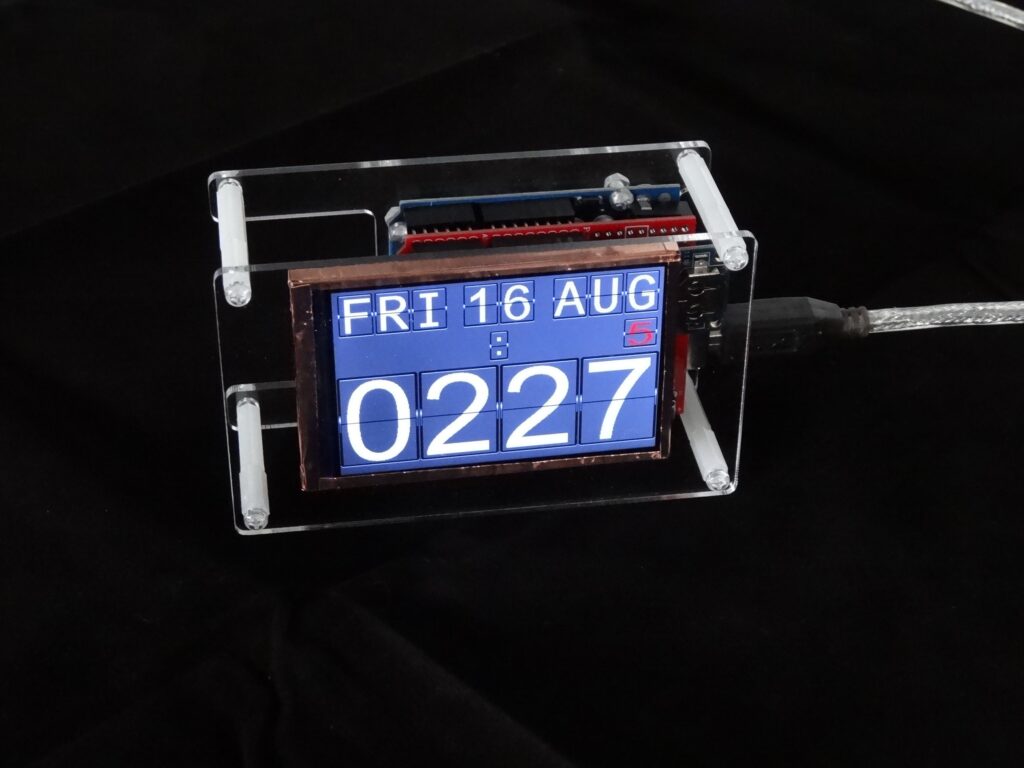
Although flip clocks may be extremely interesting electromechanical devices, with rolling flaps to show what time it is, they’re also fairly complicated if you want to build one yourself. Mark Wilson, however, took a different approach with his project, simulating the output on a 320×240 LCD display.
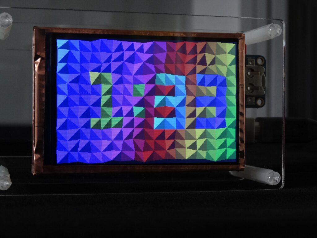
The clock is powered by an Arduino Uno and a DS3231 RTC module, allowing it to show the time, date, a blinking colon, and even the days until the trash/recycling needs to be put out. Alternate screens are available as well, including a Pong clock, triangle clock, and cube clock, which can be individually selected or set to randomly cycle if you so desire.
For its housing, Wilson chose a minimal acrylic/standoff design that seems to suit it well, and you can see it in action in the short demo clip below.