This year, Maker Faire Shenzhen 2019 will be focusing on the theme “To the Heart of Community, To the Cluster of Industry”. With a full chain events for technological innovations, you can look forward to the Maker Summit Forum, Maker Booths (includes highlights and performances), as well as Innovation workshops. […]
While the Arduino has a very vocal fan club, there are always a few people less than thrilled with the ubiquitous ecosystem. While fans may just dismiss it as sour grapes, there are a few legitimate complaints you can fairly level at the stock setup. To address at least some of those concerns, Arduino is rolling out the Arduino Pro IDE and while it doesn’t completely address every shortcoming, it is worth a look and may grow to quiet down some of the other criticisms, given time.
For the record, we think the most meaningful critiques fall into three categories: 1) the primitive development environment, 2) the convoluted build system, and 3) the lack of debugging. Of course, there are third party answers for all of these problems, but now the Pro IDE at least answers the first one. As far as we can tell, the IDE hides the build process just like the original IDE. Debugging, though, will have to wait for a later build.
We were happy to see a few things with the new IDE. There’s some autocompletion support, Git is integrated, and there’s still our old friend the serial monitor. The system still uses the Arduino CLI, so that means there isn’t much danger of the development getting out of sync. The actual editor is Eclipse Theia. People typically either love Eclipse or hate it, however, it is at least a credible editor. However, Theia uses Electron which makes many people unhappy because Electron applications typically eat a lot of resources. We’ll have to see how taxing using the new Pro IDE is on typical systems with normal workloads.
On the future feature list is our number one pick: debugging. They are also promising support for new languages, third party plugins, and synchronization with the Web-based editor. All good features.
This is just an alpha preview release, but it is a great start. Our only question is will existing users really care? Most people already write code in another editor. Many use an external build system like PlatformIO. Eclipse already has a plug in for Arduino that supports debugging with the right hardware. So while new users may appreciate the features, advanced users may be wondering why this is so late to the party.
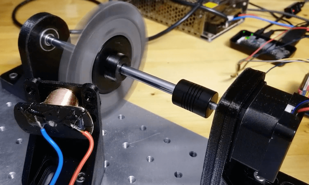
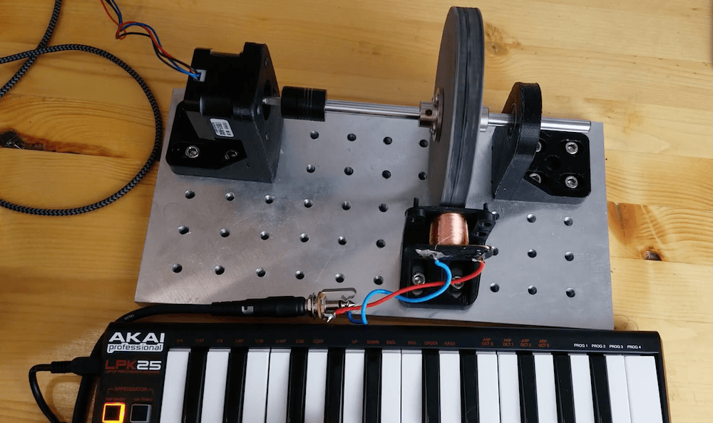
YouTuber “The Mixed Signal” has come up with a fun way to make music: spinning a gear-like ferromagnetic tonewheel next to a homemade coil pickup.
A stepper motor turns the wheel using a CNC shield under Arduino control. When set up, it’s simply a matter of programming in the proper speed via G-code to create the correct sound.
The concept isn’t entirely new, as this type of assembly was used in Hammond organs produced in the middle of the last century. The Mixed Signal’s project, however, is a very interesting take on this technology, with the use of 3D-printed parts including the iron-embedded tonewheel, as well as the integration of a MIDI keyboard.
Trigonometry is a struggle for some students. Perhaps one of the reasons for this is that instruction can be something of a one-way street, and concepts can be hard to grasp until more technical building blocks are learned.
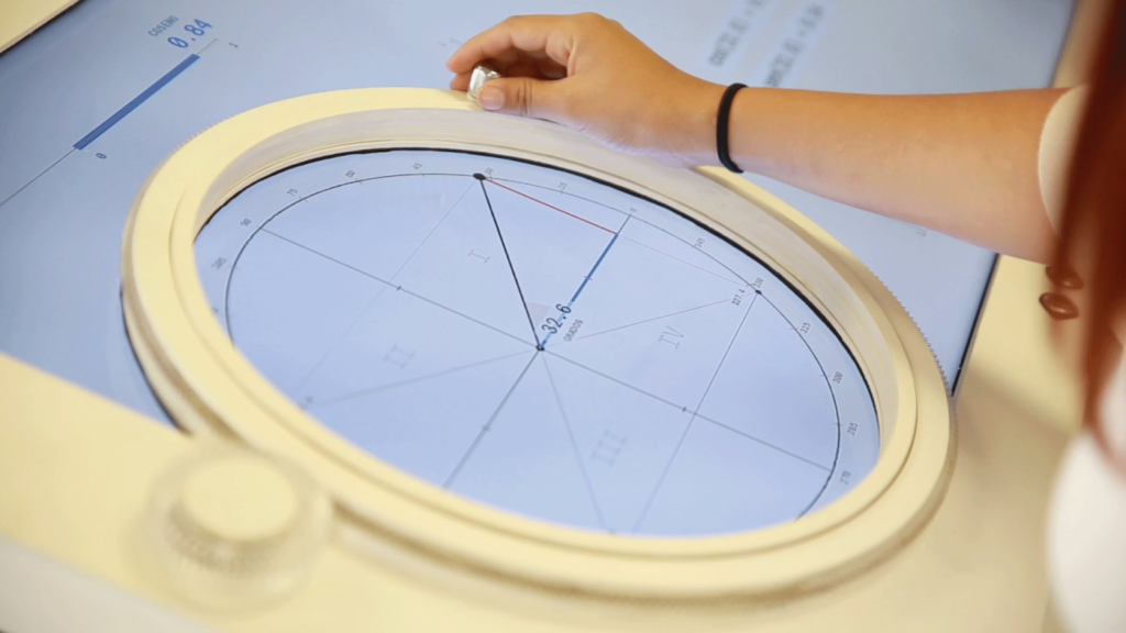
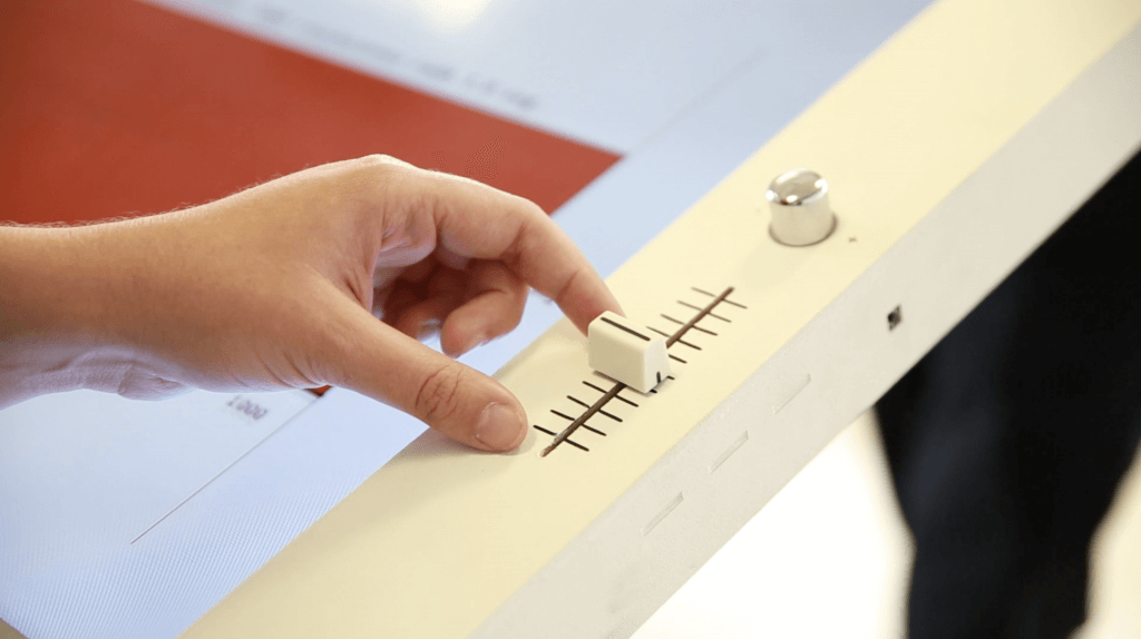
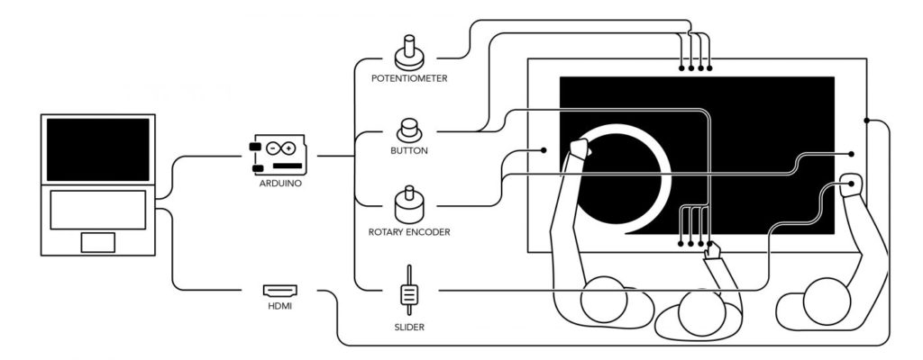
As seen here, researchers at the Universidad del Desarrollo in Chile aim to change that with a trigonometry tabletop display called TAMI, or Tangible Mathematics Interface. This nearly horizontal screen shows mathematical relationships, while allowing students to interact with them using physical controls.
The most prominent controller here is a large rotary wheel. Students rotate this to modify the angle shown in the middle, and observe how concepts like sine and cosine react to this manipulation. An Arduino Leonardo takes input from this and other controls, and passes it along to a computer. This then handles on-screen info and even plays sounds as needed!
This post was originally published by Sandeep Mistry and Dominic Pajakon the TensorFlow blog.
Arduino is on a mission to make machine learning simple enough for anyone to use. We’ve been working with the TensorFlow Lite team over the past few months and are excited to show you what we’ve been up to together: bringing TensorFlow Lite Micro to the Arduino Nano 33 BLE Sense. In this article, we’ll show you how to install and run several new TensorFlow Lite Micro examples that are now available in the Arduino Library Manager.
The first tutorial below shows you how to install a neural network on your Arduino board to recognize simple voice commands.
Example 1: Running the pre-trained micro_speech inference example.
Next, we’ll introduce a more in-depth tutorial you can use to train your own custom gesture recognition model for Arduino using TensorFlow in Colab. This material is based on a practical workshop held by Sandeep Mistry and Dan Coleman, an updated version of which is now online.
If you have previous experience with Arduino, you may be able to get these tutorials working within a couple of hours. If you’re entirely new to microcontrollers, it may take a bit longer.
Example 2: Training your own gesture classification model.
We’re excited to share some of the first examples and tutorials, and to see what you will build from here. Let’s get started!
Note: The following projects are based on TensorFlow Lite for Microcontrollers which is currently experimental within the TensorFlow repo. This is still a new and emerging field!
Microcontrollers and TinyML
Microcontrollers, such as those used on Arduino boards, are low-cost, single chip, self-contained computer systems. They’re the invisible computers embedded inside billions of everyday gadgets like wearables, drones, 3D printers, toys, rice cookers, smart plugs, e-scooters, washing machines. The trend to connect these devices is part of what is referred to as the Internet of Things.
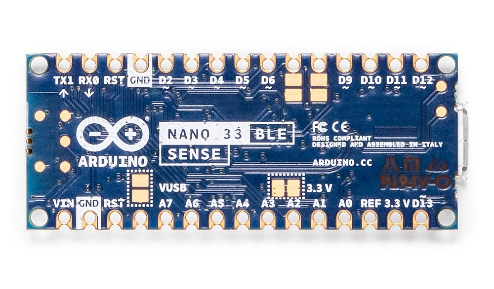
Arduino is an open-source platform and community focused on making microcontroller application development accessible to everyone. The board we’re using here has an Arm Cortex-M4 microcontroller running at 64 MHz with 1MB Flash memory and 256 KB of RAM. This is tiny in comparison to Cloud, PC, or mobile but reasonable by microcontroller standards.
Arduino Nano 33 BLE Sense board is smaller than a stick of gum.
There are practical reasons you might want to squeeze ML on microcontrollers, including:
Function – wanting a smart device to act quickly and locally (independent of the Internet).
Cost – accomplishing this with simple, lower cost hardware.
Privacy – not wanting to share all sensor data externally.
Efficiency – smaller device form-factor, energy-harvesting or longer battery life.
There’s a final goal which we’re building towards that is very important:
Machine learning can make microcontrollers accessible to developers who don’t have a background in embedded development
On the machine learning side, there are techniques you can use to fit neural network models into memory constrained devices like microcontrollers. One of the key steps is the quantization of the weights from floating point to 8-bit integers. This also has the effect of making inference quicker to calculate and more applicable to lower clock-rate devices.
TinyML is an emerging field and there is still work to do – but what’s exciting is there’s a vast unexplored application space out there. Billions of microcontrollers combined with all sorts of sensors in all sorts of places which can lead to some seriously creative and valuable TinyML applications in the future.
A Micro USB cable to connect the Arduino board to your desktop machine
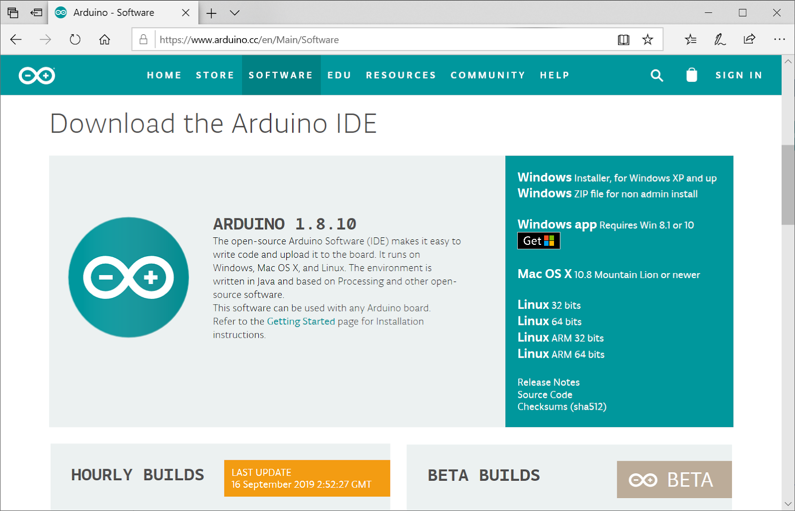
To program your board, you can use the Arduino Web Editor or install the Arduino IDE. We’ll give you more details on how to set these up in the following sections
The Arduino Nano 33 BLE Sense has a variety of onboard sensors meaning potential for some cool TinyML applications:
Environmental – temperature, humidity and pressure
Light – brightness, color and object proximity
Unlike classic Arduino Uno, the board combines a microcontroller with onboard sensors which means you can address many use cases without additional hardware or wiring. The board is also small enough to be used in end applications like wearables. As the name suggests it has Bluetooth LE connectivity so you can send data (or inference results) to a laptop, mobile app or other BLE boards and peripherals.
Tip: Sensors on a USB stick – Connecting the BLE Sense board over USB is an easy way to capture data and add multiple sensors to single board computers without the need for additional wiring or hardware – a nice addition to a Raspberry Pi, for example.
TensorFlow Lite for Microcontrollers examples
The inference examples for TensorFlow Lite for Microcontrollers are now packaged and available through the Arduino Library manager making it possible to include and run them on Arduino in a few clicks. In this section we’ll show you how to run them. The examples are:
micro_speech – speech recognition using the onboard microphone
magic_wand – gesture recognition using the onboard IMU
person_detection – person detection using an external ArduCam camera
For more background on the examples you can take a look at the source in the TensorFlow repository. The models in these examples were previously trained. The tutorials below show you how to deploy and run them on an Arduino. In the next section, we’ll discuss training.
How to run the examples using Arduino Create web editor
Once you connect your Arduino Nano 33 BLE Sense to your desktop machine with a USB cable you will be able to compile and run the following TensorFlow examples on the board by using the Arduino Create web editor:
Compiling an example from the Arduino_TensorFlowLite library.
Focus on the speech recognition example: micro_speech
One of the first steps with an Arduino board is getting the LED to flash. Here, we’ll do it with a twist by using TensorFlow Lite Micro to recognise voice keywords. It has a simple vocabulary of “yes” and “no”. Remember this model is running locally on a microcontroller with only 256KB of RAM, so don’t expect commercial ‘voice assistant’ level accuracy – it has no Internet connection and on the order of 2000x less local RAM available.
Note the board can be battery powered as well. As the Arduino can be connected to motors, actuators and more this offers the potential for voice-controlled projects.
Running the micro_speech example.
How to run the examples using the Arduino IDE
Alternatively you can use try the same inference examples using Arduino IDE application.
First, follow the instructions in the next section Setting up the Arduino IDE.
In the Arduino IDE, you will see the examples available via the File > Examples > Arduino_TensorFlowLite menu in the ArduinoIDE.
Select an example and the sketch will open. To compile, upload and run the examples on the board, and click the arrow icon:
For advanced users who prefer a command line, there is also the arduino-cli.
Training a TensorFlow Lite Micro model for Arduino
Gesture classification on Arduino BLE 33 Nano Sense, output as emojis.
Next we will use ML to enable the Arduino board to recognise gestures. We’ll capture motion data from the Arduino Nano 33 BLE Sense board, import it into TensorFlow to train a model, and deploy the resulting classifier onto the board.
The idea for this tutorial was based on Charlie Gerard’s awesome Play Street Fighter with body movements using Arduino and Tensorflow.js. In Charlie’s example, the board is streaming all sensor data from the Arduino to another machine which performs the gesture classification in Tensorflow.js. We take this further and “TinyML-ifiy” it by performing gesture classification on the Arduino board itself. This is made easier in our case as the Arduino Nano 33 BLE Sense board we’re using has a more powerful Arm Cortex-M4 processor, and an on-board IMU.
We’ve adapted the tutorial below, so no additional hardware is needed – the sampling starts on detecting movement of the board. The original version of the tutorial adds a breadboard and a hardware button to press to trigger sampling. If you want to get into a little hardware, you can follow that version instead.
Setting up the Arduino IDE
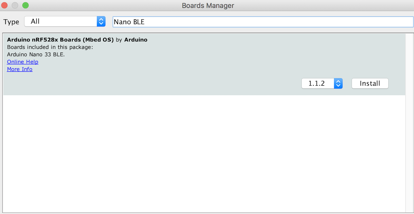
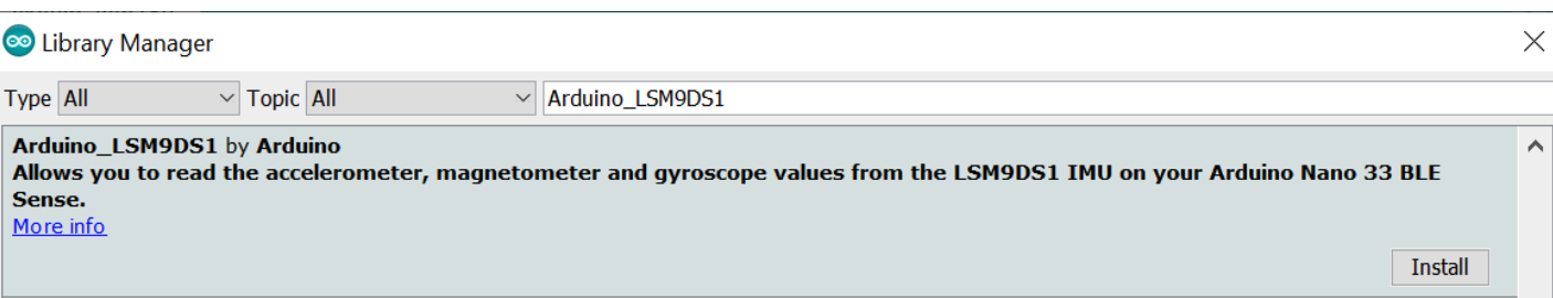
Following the steps below sets up the Arduino IDE application used to both upload inference models to your board and download training data from it in the next section. There are a few more steps involved than using Arduino Create web editor because we will need to download and install the specific board and libraries in the Arduino IDE.
First, we need to capture some training data. You can capture sensor data logs from the Arduino board over the same USB cable you use to program the board with your laptop or PC.
Arduino boards run small applications (also called sketches) which are compiled from .ino format Arduino source code, and programmed onto the board using the Arduino IDE or Arduino Create.
We’ll be using a pre-made sketch IMU_Capture.ino which does the following:
Monitor the board’s accelerometer and gyroscope
Trigger a sample window on detecting significant linear acceleration of the board
Sample for one second at 119Hz, outputting CSV format data over USB
Loop back and monitor for the next gesture
The sensors we choose to read from the board, the sample rate, the trigger threshold, and whether we stream data output as CSV, JSON, binary or some other format are all customizable in the sketch running on the Arduino. There is also scope to perform signal preprocessing and filtering on the device before the data is output to the log – this we can cover in another blog. For now, you can just upload the sketch and get sampling.
To program the board with this sketch in the Arduino IDE:
Compile and upload it to the board with Sketch > Upload
Visualizing live sensor data log from the Arduino board
With that done we can now visualize the data coming off the board. We’re not capturing data yet this is just to give you a feel for how the sensor data capture is triggered and how long a sample window is. This will help when it comes to collecting training samples.
In the Arduino IDE, open the Serial Plotter Tools > Serial Plotter
If you get an error that the board is not available, reselect the port:
Tools > Port > portname (Arduino Nano 33 BLE)
Pick up the board and practice your punch and flex gestures
You’ll see it only sample for a one second window, then wait for the next gesture
You should see a live graph of the sensor data capture (see GIF below)
Arduino IDE Serial Plotter will show a live graph of CSV data output from your board.
When you’re done be sure to close the Serial Plotter window – this is important as the next step won’t work otherwise.
Capturing gesture training data
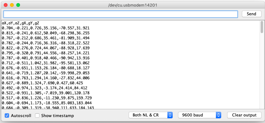
To capture data as a CSV log to upload to TensorFlow, you can use Arduino IDE > Tools > Serial Monitor to view the data and export it to your desktop machine:
Reset the board by pressing the small white button on the top
Pick up the board in one hand (picking it up later will trigger sampling)
In the Arduino IDE, open the Serial Monitor Tools > Serial Monitor
If you get an error that the board is not available, reselect the port:
Tools > Port > portname (Arduino Nano 33 BLE)
Make a punch gesture with the board in your hand (Be careful whilst doing this!)
Make the outward punch quickly enough to trigger the capture
Return to a neutral position slowly so as not to trigger the capture again
Repeat the gesture capture step 10 or more times to gather more data
Copy and paste the data from the Serial Console to new text file called punch.csv
Clear the console window output and repeat all the steps above, this time with a flex gesture in a file called flex.csv
Make the inward flex fast enough to trigger capture returning slowly each time
Note the first line of your two csv files should contain the fields aX,aY,aZ,gX,gY,gZ.
Linux tip: If you prefer you can redirect the sensor log output from the Arduino straight to a .csv file on the command line. With the Serial Plotter / Serial Monitor windows closed use:
$ cat /dev/cu.usbmodem[nnnnn] > sensorlog.csv
Training in TensorFlow
We’re going to use Google Colab to train our machine learning model using the data we collected from the Arduino board in the previous section. Colab provides a Jupyter notebook that allows us to run our TensorFlow training in a web browser.
Arduino gesture recognition training colab.
The colab will step you through the following:
Set up Python environment
Upload the punch.csv and flex.csv data
Parse and prepare the data
Build and train the model
Convert the trained model to TensorFlow Lite
Encode the model in an Arduino header file
The final step of the colab is generates the model.h file to download and include in our Arduino IDE gesture classifier project in the next section:
Create a new tab in the IDE. When asked name it model.h
Open the model.h tab and paste in the version you downloaded from Colab
Upload the sketch: Sketch > Upload
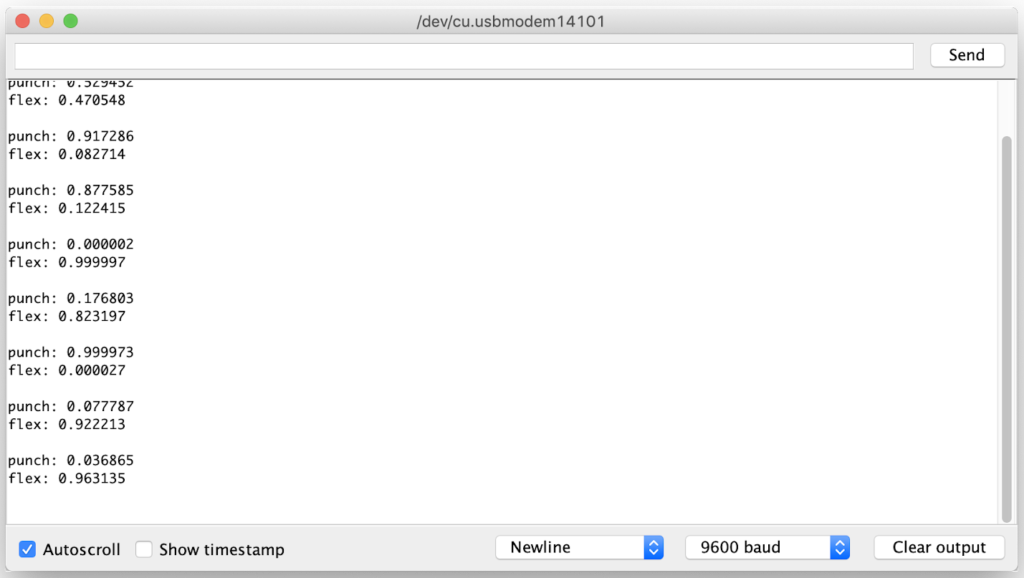
Open the Serial Monitor: Tools > Serial Monitor
Perform some gestures
The confidence of each gesture will be printed to the Serial Monitor (0 = low confidence, 1 = high confidence)
Congratulations you’ve just trained your first ML application for Arduino!
For added fun the Emoji_Button.ino example shows how to create a USB keyboard that prints an emoji character in Linux and macOS. Try combining the Emoji_Button.ino example with the IMU_Classifier.ino sketch to create a gesture controlled emoji keyboard ?.
Conclusion
It’s an exciting time with a lot to learn and explore in TinyML. We hope this blog has given you some idea of the potential and a starting point to start applying it in your own projects. Be sure to let us know what you build and share it with the Arduino community.
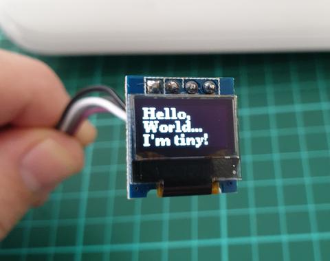
In this article we look at the tiny 0.49″ 64×32 graphic OLED from PMD Way. It is a compact and useful display, that only requires a small amount of time to get working with your Arduino or compatible board.
The purpose of this guide is to get your display successfully operating with your Arduino, so you can move forward and experiment and explore further types of operation with the display.
This includes installing the Arduino library, making a succesful board connection and running a demonstration sketch. So let’s get started!
Connecting the display to your Arduino
The display uses the I2C data bus for communication, and is a 5V and 3.3V-tolerant board.
Arduino Uno to Display
GND ---- GND (GND)

5V/3.3V- Vcc (power supply, can be 3.3V or 5V)

A5 ----- SCL (I2C bus clock)

A4 ----- SDA (I2C bus data)
I2C pinouts vary for other boards. Arduino Leonard uses D2/D3 for SDA and SCL or the separate pins to the left of D13. Arduino Mega uses D20/D21 for SDA and SCL. If you can’t find your I2C pins on other boards, email admin at tronixstuff dot com for assistance.
Installing the Arduino library
To install the library – simply open the Arduino IDE and select Manage Libraries… from the Tools menu. Enter “u8g2” in the search box, and after a moment it should appear in the results as shown in the image below. Click on the library then click “Install”:
After a moment the library will be installed and you can close that box.
Now it’s time to check everything necessary is working. Open a new sketch in the IDE, then copy and paste the following sketch into the IDE (you may find the “view raw” link at the end useful):
Your display should go through the demonstration of various font sizes and so on as shown in the video below:
You can see how we’ve used a different font in the sketch – at lines 19, 30 and 38. The list of fonts included with the library are provided at https://github.com/olikraus/u8g2/wiki/fntlistall.
Note that the initial location for each line of text (for example in line 20):
u8g2.drawStr(0, 5, "Hello,"); // write something to the internal memory
The x and y coordinates (0,5) are for the bottom-left of the first character.
If you want to display values, not text – such as integers, use:
u8g2.print();
… an example of which is show around line 49 in the example sketch.
Where to from here?
Now it’s time for you to explore the library reference guide which explains all the various functions available to create text and graphics on the display, as well as the fonts and so on. These can all be found on the right-hand side of the driver wiki page.
And that’s all for now. This post brought to you by pmdway.com – everything for makers and electronics enthusiasts, with free delivery worldwide.
To keep up to date with new posts at tronixstuff.com, please subscribe to the mailing list in the box on the right, or follow us on twitter @tronixstuff.
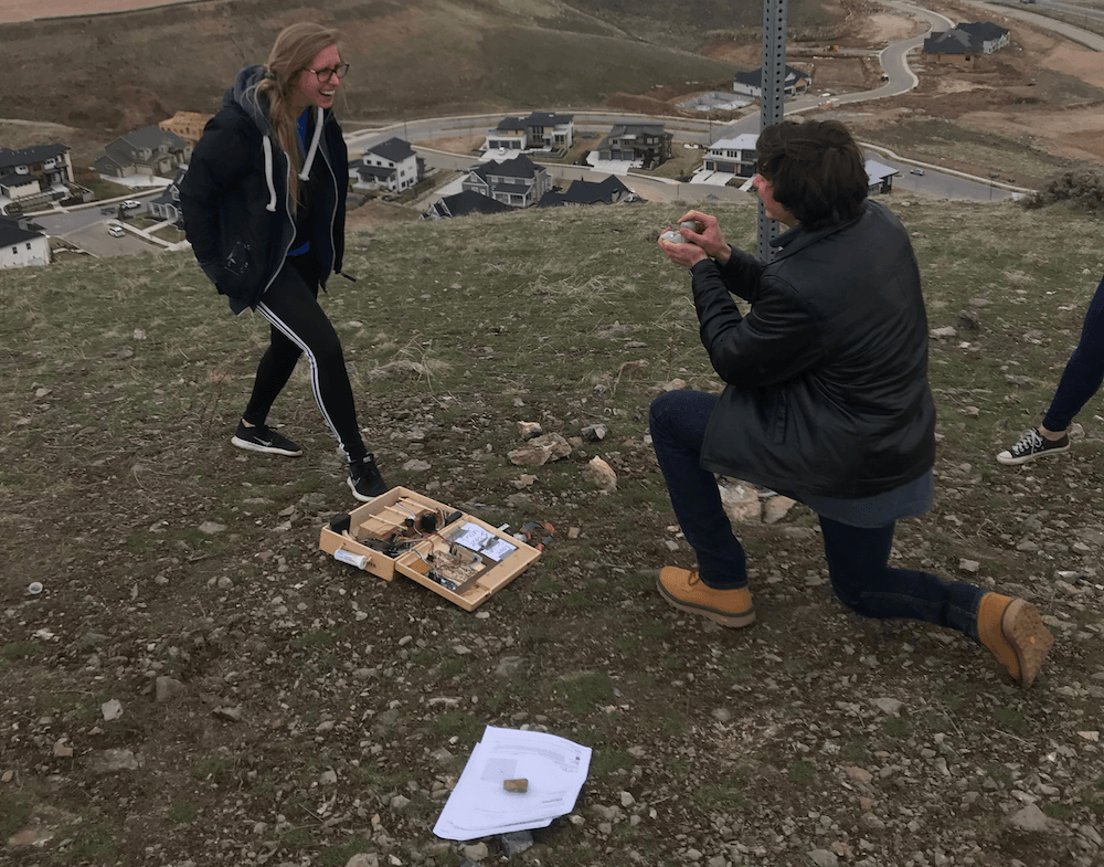
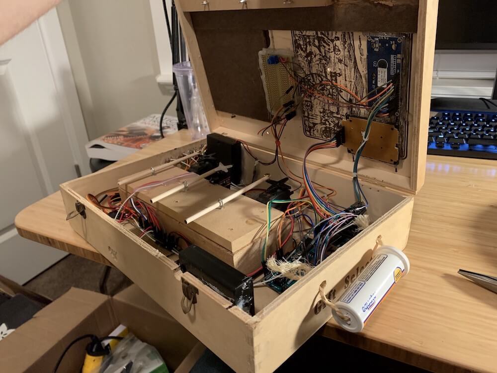
Software engineer Josh Robertson decided to come up with his own take on a marriage proposal, building a reverse geocache device for the job that uses not one, but two Arduino Uno boards.
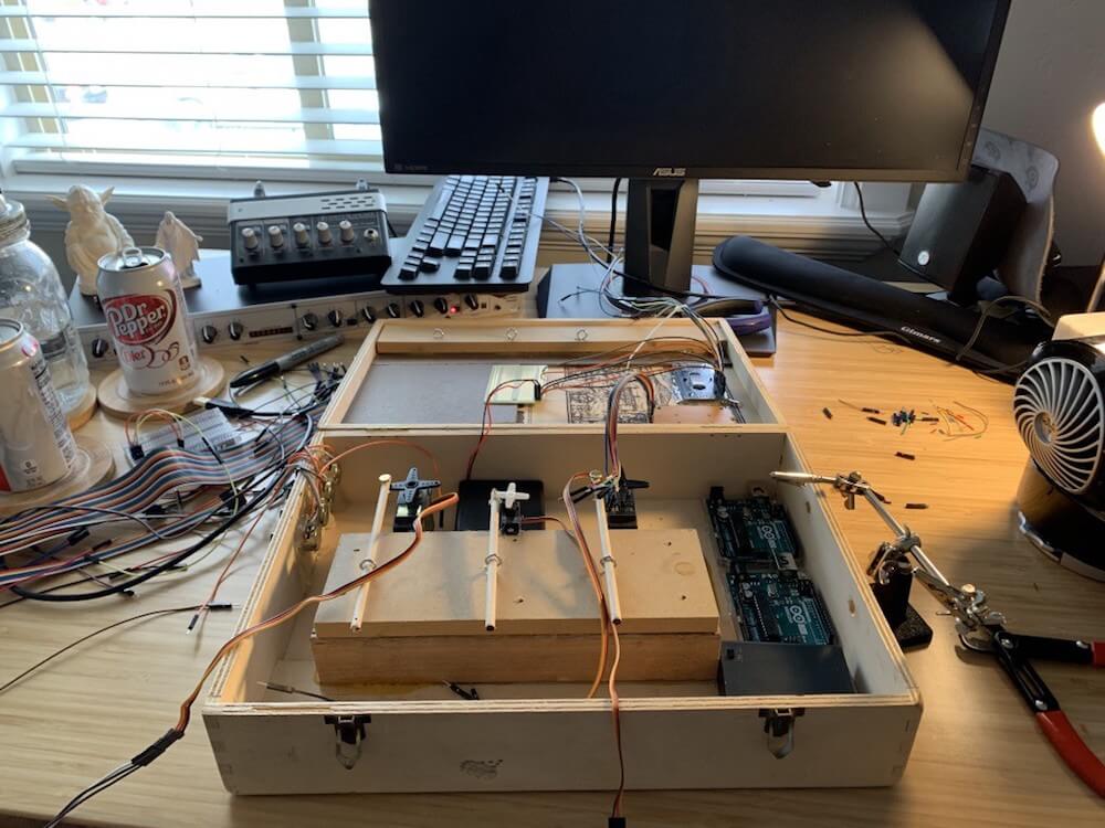
The unit, which is made out of a wine box, is unlocked by three servos that actuate rods to release a trio of clasps. His not-yet-fiancé had to first input the correct sequence on a keypad, then turn potentiometers to the right position, and finally traipse to the accurate location—sensed via GPS—for it to open up.
As the project’s I/O requirements went beyond a single Uno, Robertson linked a pair together using the I2C protocol, allowing the master to read GPS coordinates and control a small LCD screen, while the second Arduino takes care of user input and servo actuation.
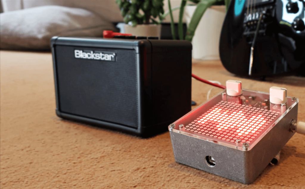
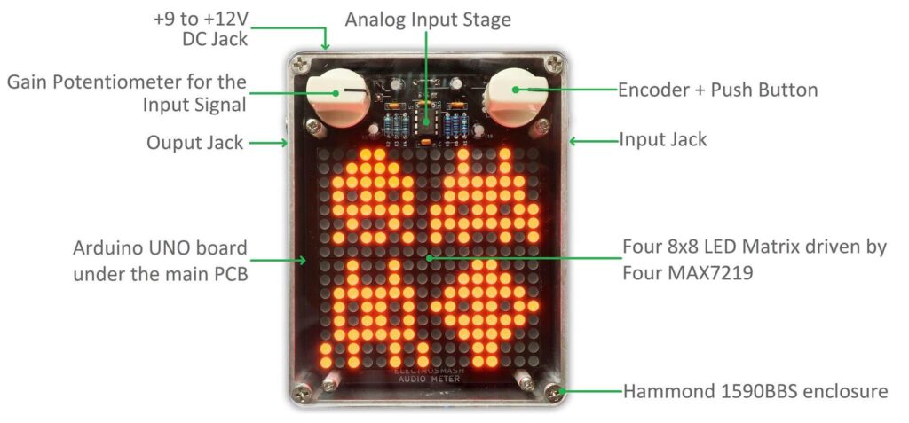
Normally guitar pedals take in a signal from your instrument, then some modification to an amplifier. ElectroSmash’s open source device, however, looks like a guitar pedal, connects to a guitar and amp like a guitar pedal, but actually leaves the signal unmodified. Instead, it displays a variety of info about what you’re playing on its 16 x 16 LED matrix.
The Arduino Audio Meter uses an Uno for control and analysis, and acts as a VU meter by reading the incoming audio and creating LED animations. It also features a tuner function, visual metronome, frequency detector, and a simple lamp, which could all certainly be useful when playing.
User input (besides the1/4-inch audio jack) is via a potentiometer and encoder, and it even has a few games available for it if you need to blow off some steam between sets! Build kits are available here if you’d like to make your own.
Due to pedalboard size, complicated guitar pedals sometimes reduce the number of buttons to the bare minimum. Many of these pedals are capable of being controlled with an external MIDI controller, however, and necessity being the mother of invention and all, this is a great opportunity to build something and learn some new skills at the same time. In need of a MIDI controller, Reddit user [Earthwin] built an Arduino powered one to control his Boss DD500 Looper pedal and the result is great looking.
Five 16×2 LCD screens, one for each button, show the functionality that that button currently has. They are attached (through some neat wiring) to a custom-built PCB which holds the Arduino that controls everything. The screens are mounted to an acrylic backplate which holds the screens in place while the laser-cut acrylic covers are mounted to the same plate through the chassis. The chassis is a standard Hammond aluminum box that was sanded down, primed and then filler was used to make the corners nice and smooth. Flat-top LEDs and custom 3D printed washers finish off the project.
[Earthwin] admits that this build might be overkill for the looper that he’s using, but he had fun building the controller and learning to use an Arduino. He’s already well on his way to building another, using the lessons learned in this build. If you want to build your own MIDI controller, this article should help you out. And then you’re ready to build your controller into a guitar if you want to.
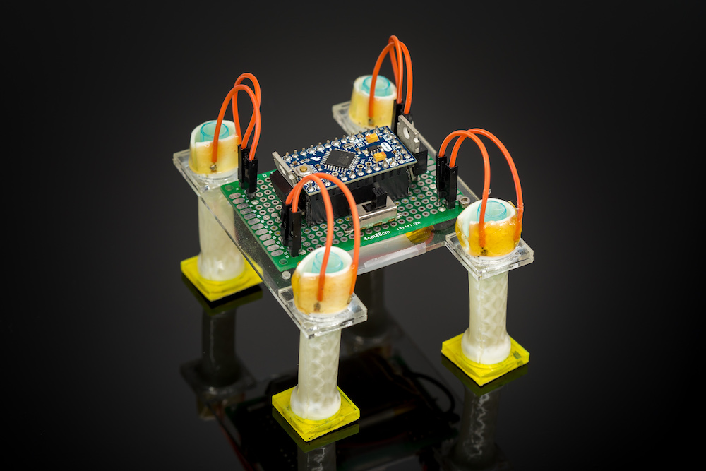
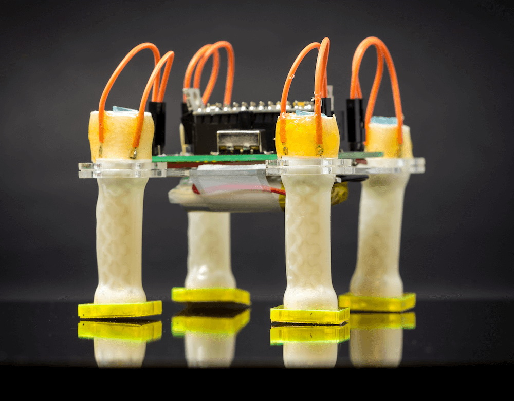
Engineers at the University of California San Diego have come up with a way to build soft robots that are compact, portable and multifunctional without the requirement for compressed air.
Instead, they’re using a system of tubular actuators made out of heat-sensitive liquid crystal elastomer sheets. Heating elements are placed between two layers of elastomer, which is then rolled up into a cylinder, allowing the tubular digit to bend and contract.
With this novel method, they’ve been able to build a three-jaw gripper, as well as a robot that walks independently with four legs under Arduino control. While the grippers are slow at this point, taking 30 seconds to bend and minutes to return to their original position, the eventual goal is to have them react at the speed of human muscles.


 This year, Maker Faire Shenzhen 2019 will be focusing on the theme “To the Heart of Community, To the Cluster of Industry”. With a full chain events for technological innovations, you can look forward to the Maker Summit Forum, Maker Booths (includes highlights and performances), as well as Innovation workshops. […]