Posts with «vacuum fluorescent display» label

VFD Character Display Turned Into Audio VU Meter

Humans love visualising music, whether it’s in the form of an inscrutable equation drawing squiggles in Winamp, or a simple VU meter pulsing with the beat. This build from [mircemk] is of the latter variety, repurposing a VFD display to do the job.

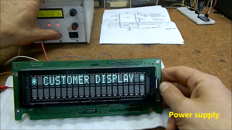
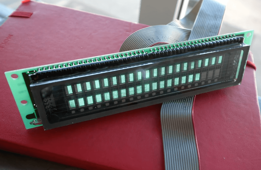
The project is built around a VFM202MDA vacuum fluorescent display, which provides that lovely green-blue glow we all know and love, driven by a PT6314 driver chip. This has the benefit that it can be readily driven by a microcontroller in much the same way as the familiar HD44780 character LCD driver chip. With some minor tweaks, the character set can be modified to allow the display to become a surprisingly-responsive VU meter.

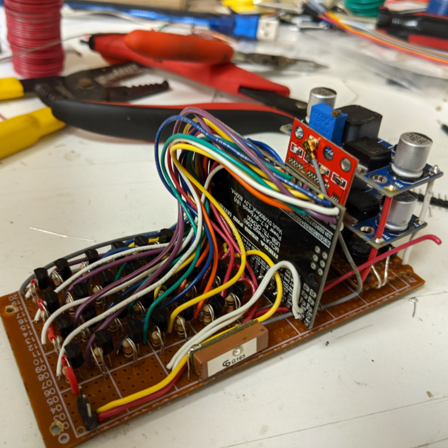
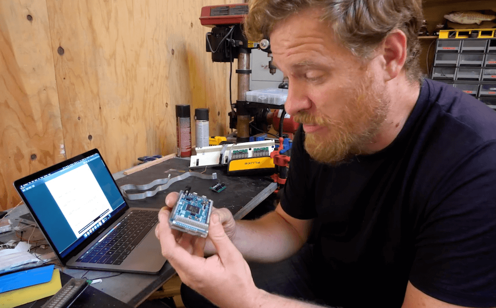
An Arduino Nano runs the show, with an envelope follower circuit feeding a signal for the left and right channels into the analog inputs of the microcontroller. The Arduino then measures the voltage on those inputs and feeds the necessary commands to the PT6314 driver to update the display.

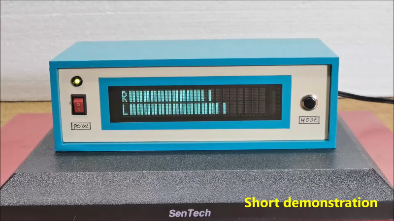
The resulting VU meter has 38 bars per channel, and is highly responsive. The fast flickering of the meter bars in response to the music make it compelling to watch, and the era-appropriate enclosure the project is built in adds plenty to the aesthetic.

We’ve seen other VU meter builds before too, like this one that uses a little physics knowledge to create a more realistic analog-like needle meter. Video after the break.


Using Arduinos To Drive Undocumented Displays

For those of us old enough to remember the VCR (and the difficulty of programming one), the ubiquitous vacuum fluorescent display, or VFD, is burned into our memories, mostly because of their brightness and contrast when compared to the superficially-similar LCD. These displays are incredibly common even apart from VCRs, though, and it’s easy to find them for next to no cost, but figuring out how to drive one if you just pulled it out of a 30-year-old VCR is going to take some effort. In this build, [mircemk] shows us how he drives unknown VFD displays using an Arduino in order to build his own weather forecasting station.

For this demonstration [mircemk] decided to turn a VFD into a weather forecasting station. First of all, though, he had to get the VFD up and running. For this unit, which came from a point-of-sale (POS) terminal, simply connecting power to the device turned on a demo mode for the display which let him know some information about it. From there, and with the knowledge that most POS terminals use RS232 to communicate, he was able to zero in on the Rx and Tx pins on the on-board microcontroller and interface them with an Arduino. From there it’s a short step to being able to output whatever he wanted to this display.

For this project, [mircemk] wanted the display to output information about weather, but rather than simply pull data from some weather API he is actually using a sensor suite connected to the Arduino to measure things like barometric pressure in order to make a 12-hour forecast. The design is inspired by old Zambretti weather forecasters which used analog wheels to input local weather data. It’s an interesting build not only for the VFD implementation but also for attempting to forecast the weather directly with just a tiny sensor set instead of downloading a forecast to display. To do any better with your own forecasts, you’d likely need your own weather station.

Captivating Clock Puts Endangered Displays On Display

The DT-1704 VFD as seen the 1976 Radio Shack Catalog. The “A” version has no substrate, making the VFD fully clear for added effect.

When you have a small stock of vacuum fluorescent displays (VFDs) straight out of the 1976 Radio Shack catalog, you might sit around wondering what to do with them. When [stepawayfromthegirls] found out that his stash of seven DT-1704A tubes may be the last in existence, there was no question. They must be displayed! [stepawayfromthegirls]’ mode of display is this captivating clock build. Four VFDs with their aqua colored elements are set against a black background in a bespoke wooden case. Looking under the hood, the beauty only increases.

VFD Clock Wiring is nearly as stunning as the clock itself.

Keeping the build organized was not an easy task because the tubes are designed in such a way that each segment must be individually controlled. The needed I/O duties are provided by an Arduino Mega 2560 Pro (Embed). 28 2n3904’s each with their two resistors serve as drivers for each VFD segment.

The output of a  24 V AC transformer left over from the 1980s is rectified to 34 V of DC power which is then regulated to 27 V to power the tubes. Switching power supplies provide 6 V to the Arduino and 1.3 V to the filaments. If you look closely, you’ll also see a GPS module so that the clock doesn’t need to be set. To future-proof the clock against daylight savings time adjustments, a potentiometer on the back of the case allows the user to set custom hour offsets without editing any code.

We think the end result is a remarkably clean, simple, and elegant clock that he will be proud of for many years to come!

If VFD clock builds are your thing, then you’ll enjoy this Network Attached VFD Clock and a Mini VFD Clock with floating display.  And while not VFD based, we’d be silly to leave out the Boat Anchor Nixie Clock with enough knobs, switches, and buttons to delight even the fussiest of hacker.


Vintage vacuum fluorescent display controlled with Arduino Due

Vacuum fluorescent displays (VFDs) have a distinct cool blue-greenish glow, and were once used in a wide range of devices, from VCRs to microwave ovens and even car dashboards. Although extremely popular way back when, they can be more difficult to source today. In the video below, Scotty Allen of the Strange Parts YouTube channel takes on the challenge of getting a $600 ISE (now Noritake) display up and running with an Arduino Due.

The process starts with examining the datasheet to find that the Due’s 3.3V logic can indeed drive the 20×2 character display, then he constructs a custom adapter board to do just that. After more datasheet lurking, head scratching and hacking, he finally got it to show “Hello world!” toward the end of the clip, along with some simple animations. 

The VFD control is part of a larger build that will be revealed in the future, and a good reminder of just how much trial and error is needed to succeed in making something awesome.

Stylish Alarm Clock Rocks a VFD

There are a great many display technologies available if you wish to make a digital clock. Many hackers seem to have a penchant for the glowier fare from the Eastern side of the Berlin Wall. [ChristineNZ] is one such hacker, and managed to secure some proper Soviet kit for an alarm clock build.

The clock employs an IV-27M vacuum fluorescent display, manufactured in the now-defunct USSR. Featuring 13 seven-segment digits, it’s got that charming blue glow that you just don’t get with other technologies. A MAX6921AWI chip is used to drive the VFD, and an Arduino Mega is the brains of the operation. There’s also an HD44780-compliant LCD that can display further alphanumeric information, and a 4×4 keypad for controlling the device.

The best part of the build though is the enclosure. The VFD is encased in a glass tube, and supported at either end by 90-degree copper pipe couplers. These hold the VFD aloft, and also act as a conduit for the wires coming off each end of the tube. It’s all built on top of a wooden base that holds the rest of the electronics.

It’s an attractive build, and we love the floating look created by the glass tube construction. It’s not the first time we’ve seen old Russian VFDs, and we doubt it will be the last. Video after the break.

Th