Arm Pelion Device Management comes to the Arduino IoT Cloud
As part of Arduino’s expanding relationship with Arm and continuing commitment to professionals, Arm Pelion Device Management users can now seamlessly use Arduino IoT Cloud to quickly create IoT applications.
Combining the speed of application development of the low-code Arduino IoT Cloud with the secure, scalable lifecycle management features of Arm Pelion Device Management brings the best of both worlds.
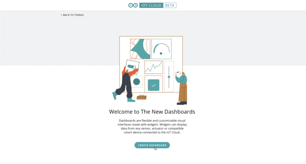
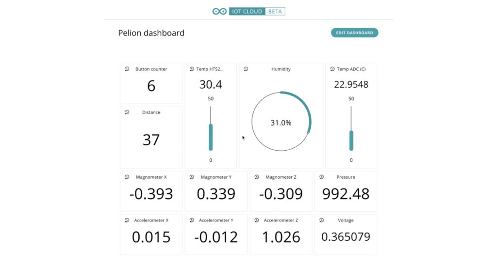
The integration enables Pelion Device Management users to import all their resources via the Pelion API and translate them into Arduino IoT Cloud properties. They can see and manage everything in the cloud, with the Arduino IoT interface (web or mobile client) providing the simplicity for designers to focus their efforts on the IoT application, creating control panels and summary dashboards. Scalability is a fundamental of the Pelion Device Management service, and new devices will automatically appear in the Arduino IoT Cloud as soon as they are registered in Pelion.
If you are an existing client of Pelion Device Management and would like to know more about the integration with Arduino IoT Cloud and the professional services available from the Arduino Pro team, please contact us here.