Posts with «arduino» label

Arduino I2C Sniffer

I’m working on an I2C project, but I don’t have a sampling oscilloscope and I need to see what the heck is going on, so I put together this quick and dirty I2C sniffer sketch.

You connect two digital pins on the Arduino to the I2C bus lines SDA and SCL, and Arduino ground to I2C ground. The digital pins on the Arduino must be on PORTD, which are pins 0 through 7. It’s probably a good idea to avoid the serial lines, which means you should use any two pins between 2 and 7.

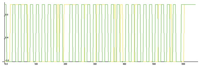
It captures the data (within a certain time window) and then it sends CSV-formatted output to the serial port. You can then take this data and plot it to get an idea of what’s going on on your I2C bus. Naturally, you could expand this to sniff other bus-types, like 1-wire or SPI, provided the signalling rate is low enough. For SPI you might trigger off the SS line. This code samples at about 2Msps on an Arduino running at 16MHz — that figure is derived from the fact that it records approximately 20 samples per 100kbit/s clock cycle.

This code runs a “one-shot” capture, meaning that it only captures data once and then dumps it to the serial port. It starts capturing when it detects the SDA line has gone low. it does not check the SCL line (as a proper start condition detector would).

You can adjust the capture window to suit your needs, though bear in mind that the ATMega328 only has 2k of RAM, so values approaching 2000 may not work so well. A value of 250 is long enough to catch one byte sent over I2C at the 100 kbit/s standard rate. The sampled data is good enough to show you the sequence of events.

If you need very specific, time-aligned data, you should use a logic analyzer or sampling oscilloscope.

For plotting, I recommend LiveGraph, which is super easy to use and runs in Java, so it’s portable.

The code is CC-BY-SA 3.0 and unsupported. Use at your own risk.

Source:

/******************************************************
Arduino I2C Sniffer

2011 J. M. De Cristofaro
CC-BY-SA 3.0
this code is unsupported -- use at your own risk!

connect one digital pin each to SCL and SDA
use pins on PORTD (Arduino UNO/Duemilanove pins #0 - 7)
do not connect to serial pins (0 & 1)!

connect GND on Arduino to GND of I2C bus
*******************************************************/

/** DESCRIPTION **/
/*******************************************************
this code runs a "one-shot" capture, meaning that
it only captures data once and then dumps it to the
serial port.

it starts capturing when it detects the SDA line has
gone low. it does not check the SCL line (as a proper
start condition detector would). 

you can adjust the capture window to suit you needs.
a value of 300 is long enough to catch one byte sent
over i2c at the 100 kbit/s standard rate. the sample
data is good enough to show you the sequence of events,
but little else.

if you need very specific, time-aligned data, you should
use a logic analyzer or sampling oscilloscope.
*******************************************************/

// assign pin values here
const char sda_pin = 2;
const char scl_pin = 7;

// sampling window
const int data_size = 250;

// array to contain sampled data
byte captured_data[data_size];

// housekeeping booleans
boolean captured;
boolean dumped;

void setup()
  {
    Serial.begin(57600);
    pinMode(sda_pin, INPUT);
    pinMode(scl_pin, INPUT);
    captured = false;
    dumped = false;
    Serial.println("Good to go, chief!");
  }

// main loop: waits for SDA to go low, then
// samples the data, then formats and dumps it
// to the serial port.
void loop()
  {
    while(digitalRead(sda_pin)==HIGH) {}
    capture();
    if (captured == true && dumped == false)
      {
        serial_dump();
        dumped = true;
      }
  }

// captures the data on PORTD and stores it in a global array
void capture()
  {
    byte tempdata;
    for (int x = 0; x < data_size; x++)
      {
        tempdata = PIND;
        captured_data[x] = tempdata;
      }
    captured = true;
  }

// reads the data out of the global array, formats it
// and outputs it to the serial port.
void serial_dump()
  {
    byte temp;
    Serial.println("sample, sda, sck");
    for(int x = 0; x < data_size; x++)
    {
      if (x<10) { Serial.print("0"); }
      if (x<100) { Serial.print("0"); }
      Serial.print(x);
      Serial.print(",     ");
      temp = bitRead(captured_data[x], sda_pin);
      if (temp == 0) { Serial.print(0); }
      else { Serial.print(1); }
      Serial.print(",   ");
      temp = bitRead(captured_data[x], scl_pin);
      if (temp == 0) { Serial.println(0); }
      else { Serial.println(1); }
    }
  }

EIA 485 over unused pairs of ethernet cable [Test]

To carry out my plan of a home automation system (domotics) made by me I am experimenting the use of the EIA 485 communications protocol. Having wired the house with lots of cat5 cables and knowing that two of the four pairs of which it is composed are not used to the speed of 100 Mb, I tried to pass the signal on these wires to see if the two streams (TCP/IP and the EIA 485) could coexist without major problems. Here’s how the test was performed:

I defined my own communication protocol as the EIA 485 only defines the physical parameters, as Master-Slave, half duplex with 14-byte frame consisting of address, the slave’s actions, 5 bytes for data and one byte for checksum and other embroidery. For each frame received correctly, the slave sends an acknowledge to the master after performing the required action. The baud rate was set to 9600 bits/s serial communication 8-n-1 (8-bit data, no parity, 1 stop bit). To test these, the master cyclically sends once per second, request to slaves to put high one of their pins to turn on and off a LED. One of the pins of the PIC was connected to another LED programmed to turn on in case of the frame error, the bit FERR in the RCSTA register is set to 1 if the stop bit is erroneously detected as zero.

I’ve programmed a simple Arduino as a master, another Arduino and a pic

16f88 as a slave. In the photo appear beside the master and slave, the PIC16F88 is placed at the other end of the network cable about 10 meters long. For the test I did not use terminating resistors nor bias resistors since with these distances it’ not required. A pair of wires is connected to pins A and B integrated the MAX485, the other was used for the reference (connected to ground, to avoid groundloops …) it according to a daisy chain connection scheme. Throughout the test I have maintained a steady stream of  TCP/IP traffic node continuously pinging the node at the other end of cable. Result is that in over an hour of practice there was never a frame error (FERR bit was never set) and all the frames have been received correctly (no checksum errors). The TCP / IP traffic has not suffered any errors or delays (0% packet loss and response times in the standard). Now we have to run the test with a much longer cable!

In spare time i started to work on an Arduino shield (with relative library) for simple eia-485 communication. If you want to help me doing this consider a small donation.

Eraclitux 02 May 14:03

EIA 485 over unused pairs of ethernet cable [Test]

To carry out my plan of a home automation system (domotics) made by me I am experimenting the use of the EIA 485 communications protocol. Having wired the house with lots of cat5 cables and knowing that two of the four pairs of which it is composed are not used to the speed of 100 Mb, I tried to pass the signal on these wires to see if the two streams (TCP/IP and the EIA 485) could coexist without major problems. Here’s how the test was performed:

I defined my own communication protocol as the EIA 485 only defines the physical parameters, as Master-Slave, half duplex with 14-byte frame consisting of address, the slave’s actions, 5 bytes for data and one byte for checksum and other embroidery. For each frame received correctly, the slave sends an acknowledge to the master after performing the required action. The baud rate was set to 9600 bits/s serial communication 8-n-1 (8-bit data, no parity, 1 stop bit). To test these, the master cyclically sends once per second, request to slaves to put high one of their pins to turn on and off a LED. One of the pins of the PIC was connected to another LED programmed to turn on in case of the frame error, the bit FERR in the RCSTA register is set to 1 if the stop bit is erroneously detected as zero.

I’ve programmed a simple Arduino as a master, another Arduino and a pic

16f88 as a slave. In the photo appear beside the master and slave, the PIC16F88 is placed at the other end of the network cable about 10 meters long. For the test I did not use terminating resistors nor bias resistors since with these distances it’ not required. A pair of wires is connected to pins A and B integrated the MAX485, the other was used for the reference (connected to ground, to avoid groundloops …) it according to a daisy chain connection scheme. Throughout the test I have maintained a steady stream of  TCP/IP traffic node continuously pinging the node at the other end of cable. Result is that in over an hour of practice there was never a frame error (FERR bit was never set) and all the frames have been received correctly (no checksum errors). The TCP / IP traffic has not suffered any errors or delays (0% packet loss and response times in the standard). Now we have to run the test with a much longer cable!

In spare time i started to work on an Arduino shield (with relative library) for simple eia-485 communication. Keep seeing my blog for news.

Eraclitux 02 May 14:03

BlinkM Smart LED as the Smallest Arduino

Did you know you can run Arduino programs on tiny BlinkM Smart LEDs? It might make BlinkM the smallest Arduino so far. To use a BlinkM as an Arduino, all you need is the free Arduino software, a low-cost AVR programmer, some wire, and a BlinkM.

Here’s a quick video showing how it all works.

BlinkM Capabilities as an Arduino

The BlinkM board doesn’t have nearly the I/O pins and other features of a real Arduino board. But it is very tiny. Here are its capabilities: - 0.4″ square (MinM), or 0.6″ square (BlinkM) - 8MHz clock speed - [...]

Todbot 22 Mar 09:17
arduino  blinkm  

Arduino Hole Dimensions Drawing

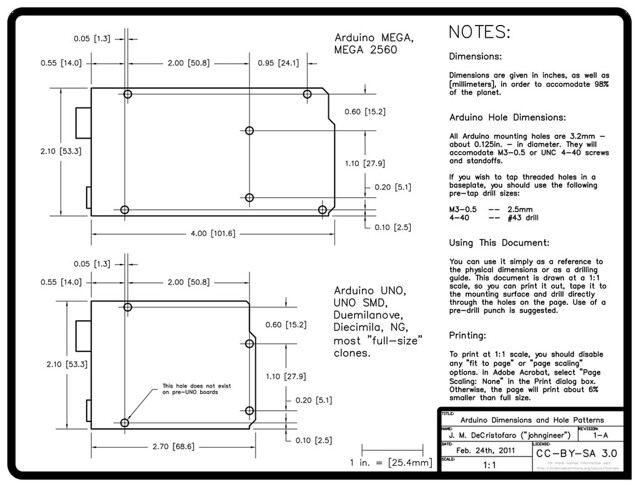
Arduinos are great, but if you’ve ever tried to mount one on a baseplate or inside an enclosure, you know it can be a pain. While there are some great enclosures specifically designed for an Arduino, if you just have a regular box that you want to use, you have to measure and mark out the holes yourself. If all you have is a ruler and a pencil, this isn’t the easiest thing to do.

In the process of working on a robot project, I needed to draw up an Arduino hole pattern and outline in CAD as part of the design. I figured others could use a similar drawing — after some polishing up, I had this Arduino hole dimension drawing (PDF).

You can use it as a reference to the dimensions or as a drilling guide. It is drawn at a scale of 1:1, so you can print it out, lay the drawing down on your mounting surface, and use a pre-drill punch directly on the paper. I’d recommend you use the punch rather than just drilling through the paper, to avoid a “walking” drill bit. If you don’t have a proper punch, you can just use a sharpened nail (we’re not fancy here).

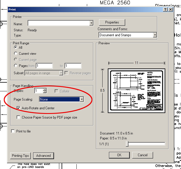
In order to get it to print 1:1, you have to turn off print scaling in Adobe Acrobat. Somewhere in the Acrobat print dialog there’s going to be a “Page Scaling” option. Set it to “None”. There’s a 1-inch scale mark next to the title block in case you want to verify that it worked.

The drawing has dimensions for both the regular Arduino and the Arduino MEGA, and the hole pattern is good for all Arduinos going back to the NG (though the diameter of the holes might be different). The new UNO boards added a fourth mounting hole, which is indicated. It should also work with most “full-size” Arduino clones, such as the EMSL Diavolino and the Seeed Studios Seeeduino, as well as the Netduino boards.

This post is cross-posted from the Adafruit Blog. Big thanks to Adafruit for hosting the PDF.

Communicate with Arduino using python

Os: linux, windows (not tested), mac osx (not tested)
Difficulty: medium
Knowledge you need: a little bit of python programming (ver 2.x) and Arduino

Let’s see how easy it is to communicate with an Arduino 2009 board and the  pySerial python’s module. What we will do is to use python to send characters serially to an Arduino 2009 which will send them back. Obviously, everything has a demonstration purposes only, since the code proposed here has no specific function but you can easily modify it to get something usable for your projects. What you describe has been tested on Ubuntu 10.04 but should work on other distributions as on various Windows and Mac OSX. If you have problems let me know!

1 Install pySerial

[Linux] Use your favorite packet manager to install python-serial or from command line type the famous command (on Ubuntu &co.):

sudo apt-get install python-serial

Type administration password and you are done!
[Windows] Download ed install pySerial (the file should be pyserial-2.5.win32.exe)

2 Download  test software

Program Arduino with this sketch Serial echo test program (403) and download the  python code Python to Arduino test program (385). Open it with a text editor and see if at line 23 in place of ’/ dev/ttyUSB0′ what you find the editor of the Arduino sketch below themenu Tools -> Serial Port -> xxxxxxx. Remeber, do not forget the single quotes!

conn = serial.Serial('/dev/ttyUSB0', timeout=1)

3 Let’s try

With Arduino programmed with the sketch above and connected to the computer launch communication.py, if it works the board will send back all the ASCII characters that you type on the keyboard. You can verify that the communication is actually taking place looking at the flashing LED TX and RX on the board. Now you can to modify these examples to suit your needs.

Ah! The python’s way…

Eraclitux 20 Feb 11:13

Communicate with Arduino using python

Os: linux, windows (not tested), mac osx (not tested)
Difficulty: medium
Knowledge you need: a little bit of python programming (ver 2.x) and Arduino

Let’s see how easy it is to communicate with an Arduino 2009 board and the  pySerial python’s module. What we will do is to use python to send characters serially to an Arduino 2009 which will send them back. Obviously, everything has a demonstration purposes only, since the code proposed here has no specific function but you can easily modify it to get something usable for your projects. What you describe has been tested on Ubuntu 10.04 but should work on other distributions as on various Windows and Mac OSX. If you have problems let me know!

1 Install pySerial

[Linux] Use your favorite packet manager to install python-serial or from command line type the famous command (on Ubuntu &co.):

sudo apt-get install python-serial

Type administration password and you are done!
[Windows] Download ed install pySerial (the file should be pyserial-2.5.win32.exe)

2 Download  test software

Program Arduino with this sketch Serial echo test program (84) and download the  python code Python to Arduino test program (98). Open it with a text editor and see if at line 23 in place of ’/ dev/ttyUSB0′ what you find the editor of the Arduino sketch below themenu Tools -> Serial Port -> xxxxxxx. Remeber, do not forget the single quotes!

conn = serial.Serial('/dev/ttyUSB0', timeout=1)

3 Let’s try

With Arduino programmed with the sketch above and connected to the computer launch communication.py, if it works the board will send back all the ASCII characters that you type on the keyboard. You can verify that the communication is actually taking place looking at the flashing LED TX and RX on the board. Now you can to modify these examples to suit your needs.

Ah! The python’s way…

Eraclitux 20 Feb 11:13

Hacking An Industrial CNC Lathe, Part I: Intro

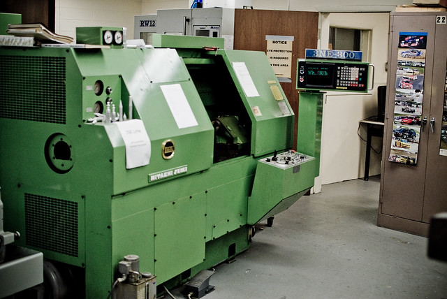
Hitachi-Seiki 3NE-300 Lathe, circa 1980

I’m currently taking some mechanical engineering classes at County College of Morris (CCM) in Randolph, NJ. Among the equipment in the machine shop is this mean, green Hitachi-Seiki CNC Lathe, a neat piece of industrial equipment from the late 70′s/early 80′s.

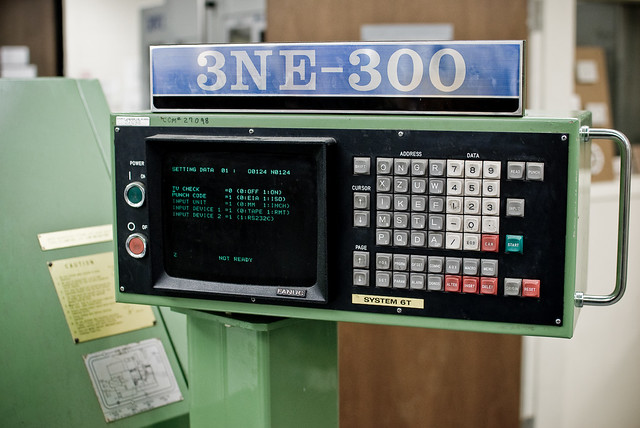
Currently, there are two ways to program the machine. You can program it manually, by entering in codes on the keypad:

3NE-300 control panel

-OR- you can get your Jacquard on and write a program on punched tape:

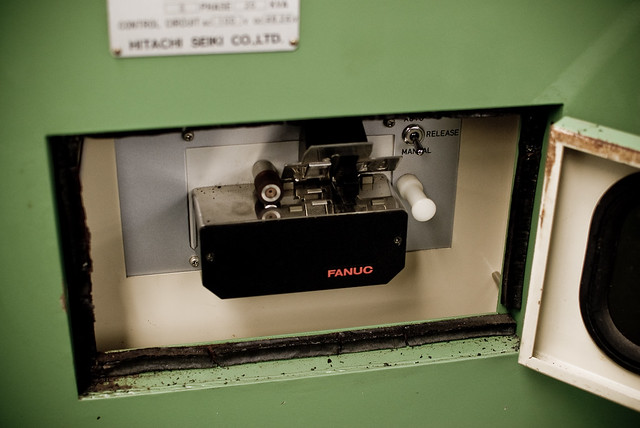
FANUC punched tape reader

Naturally, for ease of use, the punched tape reader is on the back of the machine. *sigh*

Fortunately, there is a third way to get program code into the controller. This is via an RS-232C port:

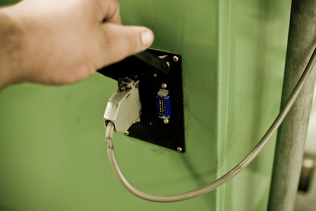
Serial port: a DB-25 RS-232-C port and an MR-20 "HONDA" connector

The obvious question is: why not just hook the serial port up to a computer? Well, due to the logistics of the shop, it’s not feasible to have a computer in the immediate vicinity of the machine. In order to hook it up to the nearest computer, the required cable would be at least 25 feet long. In practice, this translates to a 600-baud signaling rate, as there is a lot of EM interference in the shop, due to motors, fluorescent lights, etc. It’s much easier to simply have a small “black box” that can load the program from modern media like an SD card.

My plan is to build a circuit based around an Arduino, which will read an NC file (ASCII text) from an SD card and send it to the machine over the serial port. I plan to use the following hardware:

  • Arduino Mega – the brains of the operation. To be honest, I probably won’t need the extra pins of the Mega, but with the full SD library, the serial library and the extensive menu system I plan to write, I need the extra program memory.
  • LCD with Adafruit i2c/SPI backpack – for the display (file menu, load progress, etc.)
  • Adafruit Logger Shield – for reading from and writing to the SD card.
  • CuteDigi RS232 Shield – not entirely sure about this one yet. I may just get an Adafruit protoshield and wire up a DB-25 port to it.
  • Hammond 1550D enclosure – with milled openings for the SD card, LCD and buttons.

The controller for the lathe is a FANUC 6T-B. While rather primitive by today’s standards, in it’s day it was a top of the line industrial controller, and FANUC is still the standard. It’s pretty much indestructible too, which is a bonus, because it means I won’t end up scrambling the brains on a $20,000 piece of equipment.

More to come as I work on this project over winter break. I’m hoping to get the electronics soon and start work on the menu and input systems. By the time I get back to school in January, it’ll (hopefully) be ready to interface with the FANUC controller.

WiFi for Arduino with Asus WL-520gu

I love Arduino but its lack of wireless bugs me. And it sucks that WiFi Shields for the Arduino cost as much a cell phone. I want something cheap. Turns out, small, cheap WiFi routers like the Asus WL-520gu can run the DD-WRT Linux firmware and act as serial-to-network gateway for Arduinos (or most any other USB device). Here’s how to do it.

(Hey, is this a Wifi-controlled BlinkM? I think it is.)

A quick video showing a router acting as a serial-to-network gateway:

This is not that new of a concept, hacking Linux onto a router for some [...]

Todbot 16 Dec 09:48

ReflashBlinkM: Update your BlinkM’s firmware

All BlinkM-family devices can have their firmware updated. This makes them great for tiny development boards for ATtiny processors. ReflashBlinkM is an application that makes it easy to put back the original firmware or update a BlinkM to the latest firmware.

Previously you needed an AVR ISP programmer like the AVRISPmkII or the USBtinyISP. Thanks to the ArduinoISP sketch that ships with Arduino, if you have already have an Arduino, you can easily reflash your BlinkM with new firmware.

The ReflashBlinkM application is a tool for Mac OS X and Windows that uses ArduinoISP to help you reflash BlinkMs to their default [...]

Todbot 20 Nov 03:32