Posts with «arduino» label

A Brief Essay About the Benefits of Open-Source Hardware #openhardware

Didn't have a photo to go with this article, so here's a picture of a cat with an Arduino

The Other Benefits of Open-Source Hardware

Lots of people have been talking about (and questioning) the economic value of open-source
hardware. The most frequent question/criticism is that OSH facillitates the ripping off of the
original designer. That is, they publish their work openly and then someone else takes this work,
produces a product, and sells it. None of the money from this sale goes to the original designer.
In the case of less scrupulous manufacturers, no attribution is cited and all identifying marks
are removed from the product. Under these conditions, it would be rather difficult to take legal
recourse, particularly if said manufacturer is based somewhere overseas.

The argument itself is quite valid — the above scenario could happen, and I know for a fact that
it does happen. And there’s really not a damn thing you can do about it. It happens to people
whose work is protected by copyright too, if that makes you feel any better.

The problem I have with the argument above is that it’s only valid when the hardware is being
sold (or intended to be sold) commercially. This represents one way to make money from your
work, but it’s not the only way. The work itself has value too.

In her keynote address at the Open Hardware Summit, LadyAda pointed out that one of the
prime benefits of doing open hardware is that it makes you a better engineer. I’m inclined to
agree. From this standpoint, the OSH community is sort of a ‘peer-review’ journal with a very
low barrier to entry (can you put it on the internet?) and worldwide exposure (make something
cool and the blogs will pick it up). Within a week you’ll receive LOTS of peer review. Some will
be positive, much of it will be negative. Most of the negative stuff you can ignore (see rebuttal),
but a portion of the negative will be constructive, and that’s the part you should pay attention to.
This instant feedback is usually in the form of blog comments. When people really start looking
at what you’ve done and begin making changes, adding things, or using it in projects, that’s the
real peer review. It’s also the most rewarding part.

But how can this make you money, or at least help you in your professional life? The answer
is simple: it raises your profile, gets you props, and gives you cred. There are plenty of people
who bank on their own rep and get paid. That’s basically what you’re doing when you send out a
resume or CV — it’s all about what you’ve done and how you did it.

In the terms of this discussion, you get cred for three things: good design, great docs, and
actually completing the project. Good design and great documentation are fairly obvious. The
last one sounds ridiculous, but it’s not. I have no actual data to back this up, but I’m willing to bet
that the ratio of unfinished vs finished projects in the world at any moment is about 100:1, and
I’m probably being generous.

Lots of people have great ideas every day. Some people act on them. And then there are the
proud, rare few who actually finish what they’ve started. It’s not easy, particularly if you have
other things to do. Still, if you can take a project from conception through design to building and
testing, and then document the hell out of it and put it out into the wild in a finished and working
state, you get insane cred. And not just among the relatively few people who see it on a blog
and comment: “cool project!” (p.s. god bless those people).

Let’s say two engineers (A & B) want to apply to graduate school. The only project Engineer A
has on her CV is her senior project, which doesn’t work the way it should and is only minimally
documented (which pretty much describes every senior engineering project ever).

Engineer B is very similar to A — she has the same grades and a similar ‘almost working’ senior
project. But B also put together a neat little open-source hardware project on her own time, fully
tested, with complete documentation. It’s not as complex as her senior project, but it actually
works. She puts this on her CV, along with a link to the project. She also sends an email to the
department chair telling this person about her project, and mentioning that she might be thinking
about applying to grad school at his prestigious university.

If you were the department chair, who would you more like to admit into your program? The
person who is just like every other applicant, or the person who has shown the initiative and
ability to take a project from start to finish? I’m not dumb enough to make some guarantee that
doing OSH will get you into grad school, but it definitely can’t hurt you.

It’s very similar in the professional world. You have your resume and references just like
everybody else. The thing that will make you stand out is the self-motivated and fully realized
work you’ve done on the side by yourself. The demonstrated ability to document your projects
comes into play here too. Engineers hate documentation. HATE IT. Because it sucks. But
it’s a necessary evil — you can’t (or at least you shouldn’t) sell a product to a customer without
documentation. Engineers who can write docs are a valuable asset to any company — in fact,
they are critical, and always in short supply.

The open-source hardware community gives you the opportunity to “publish” your work and show off your skills,
be recognized for them, and eventually be rewarded for them. The reward may or may not be monetary,
but there’s plenty of good karma and experience to be had, and lots of cred.

End.

If you want to discuss this post, or tell me I’m wrong and call me names, you can do that here.
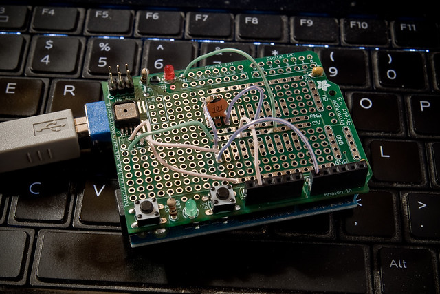
SoftI2CMaster: Add I2C to any Arduino pins

Ever wanted to use any pair of pins for I2C on Arduino, not just the dedicated pins on Analog 4 & 5? Me too, so I made a quick little Arduino library called “SoftI2CMaster”, available in the “blinkm-projects” Googlecode repository.

Get it here: SoftI2CMaster.h, SoftI2CMaster.cpp.

It’s still a work in progress, but it can write data pretty successfully and do it over longer cables than normal.

For the VIMBY/Scion Hackerspace Challenge, I created an array of BlinkM MaxM-powered accent lights for the device we made. Because the I2C cable was longer than a few feet, the normal Wire library that [...]

Todbot 25 Sep 08:14

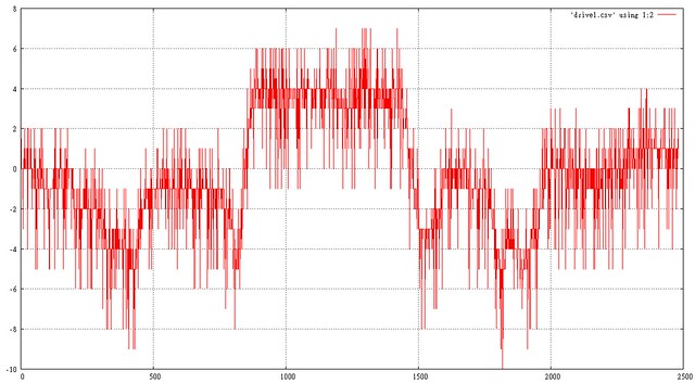
Barometric Sensor testing with Arduino

Freescale MP3H6115A baro sensor on Arduino protoshield.

bad data

good data

Click on the pictures for more info.

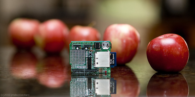
Adafruit Arduino Logshield with Apples

Adafruit Logshield for Arduino (with apples)

Playing around with shooting Adafruit products alongside fruit. I think it looks pretty nice, actually.

johnginneer 11 Sep 18:46
arduino  photo  

Slow Arduino IDE

Up until a few days ago, I’d been doing most of my Arduino development on my desktop (XP). Recently, I’ve started drafting more ideas on the go with my laptop (Vista). The problem I encountered on the laptop, which I never had on the desktop, was that the Arduino IDE was running painfully slow. It took about 30 seconds to start up, and any time I accessed the “tools” menu, it would hang for another 20 seconds. Boo!

After doing some research, I came across this thread on the Arduino forums. Reading on that thread and in other posts on the forums, it’s apparent that this is not an uncommon problem. Apparently it has to do with the rxtx library which the IDE uses to scan and manipulate COM ports, and is caused generally by the fact that the IDE is a cross-platform project but that Windows (particularly Vista) has more problems than most other platforms.

The fact that my laptop has bluetooth (I use a BT mouse and headphones) only compounds the problem. Bluetooth is something of a serial comm resource hog, but it’s also something I basically need — I can’t run Eagle without my mouse (or my music for that matter). Turning it off every time I run the Arduino IDE is not an option.

Thankfully, Arduino forum member eried did us all a great favor in isolating and solving the problem.

Here’s a link to the “fixed” rxtxSerial.dll file (wrapped in a rar). All you need to do is swap it in for the existing rxtxSerial.dll file in the Arduino directory, and you’re good to go!

johnginneer 03 Sep 02:42
arduino  

ThingM at Maker Faire 2010

My company ThingM had an official presence at Maker Faire this year. We were showing off the BlinkM line, including the new BlinkM MinM and the LinkM USB BlinkM controller. It was a lot of fun. And packed!

(click any photo to go to larger version on Flickr)

We were in the Maker Shed building, right underneath the Arduino banner, so we got lots of awesome questions about Arduino. The most common: “So I just picked up this thing that says ‘works with Arduino’…well, what *is* Arduino?” It was so great to see so many people interested [...]

Todbot 31 May 00:51
arduino  blinkm  thingm  

Acclerometer + Arduino = Aii

See what I did there…

I will have to list the Nintendo Wii as my inspiration for this project.

I’ve been working on my Arduino + accelerometer for quite some time now, but I’ve finished the code. The main features I wanted to has was to be able to send, via the serial connection, to the PC the ACTUAL values in g. So I’d know how many gs the module was pulling. I also wanted the RGB LED I’d mounted on the shield to change colours as the board was moved.

However I ran into a few problems namely, as gs are quite large units the results would be in floating point numbers. Which cannot be sent by the Arduino command “Serial.print”. I tried many work arounds, but I eventually gave up, and settled for the raw data value being sent.

And here’s the code running on the Arduino:

/* Aii - Accelerometer Shield */
/* Interfaces an accelerometer */
/* and an RBGB LED to an arduino */
/* board. TODO: use arrays? */
/* (CC) TheFallenIndustries 2007 */

int red = 3; // Outputs
int green = 6;
int blue = 5;
int fs = 4;


int x = 0; // Inputs
int y = 1;
int z = 2;
int button = 2;

int xval = 0; // Accelerometer variables
int yval = 0;
int zval = 0;

float xfloat = 0; // Values of g
float yfloat = 0;
float zfloat = 0;


int rval = 0; // PWM out variables
int gval = 0;
int bval = 0;

void setup()
{
pinMode(red,OUTPUT); // Set the RGB PWMs as outputs
pinMode(green,OUTPUT);
pinMode(blue,OUTPUT);
pinMode(button,INPUT); // Set button as an input
digitalWrite(green,LOW); // Turn off the ever-on green LED
digitalWrite(fs,HIGH); // Fullscale setting 1=6g 0=2g
beginSerial(9600);
}

void loop()
{
xval = analogRead(x); // Read the raw values
yval = analogRead(y);
zval = analogRead(z);

Serial.print("x:"); // Print the raw values
Serial.print(xval);
Serial.print(", y:");
Serial.print(yval);
Serial.print(", z:");
Serial.print(zval);
Serial.print(10, BYTE);

xfloat = xval; // set float to gravity in axis
xfloat = (xfloat - 441)/ 63;
yfloat = yval;
yfloat = (yfloat - 441)/ 63;
zfloat = zval;
zfloat = (zfloat - 441)/ 63;


rval = xval - 260; // set RGB LED PWMs
analogWrite(red,rval);
gval = yval - 260;
analogWrite(green,gval);
bval = zval - 260;
analogWrite(blue,bval);

delay(500); // Pause of 1/4 a second
}

Some changes I haven’t got round to making to the code:
Using arrays to store variables.
Using a function to convert the raw value to a value of g, and to store it as an array
General house keeping

But it worked for me in that video so all is good!


Acclerometer + Arduino = Aii

See what I did there…

I will have to list the Nintendo Wii as my inspiration for this project.

I’ve been working on my Arduino + accelerometer for quite some time now, but I’ve finished the code. The main features I wanted to has was to be able to send, via the serial connection, to the PC the ACTUAL values in g. So I’d know how many gs the module was pulling. I also wanted the RGB LED I’d mounted on the shield to change colours as the board was moved.

However I ran into a few problems namely, as gs are quite large units the results would be in floating point numbers. Which cannot be sent by the Arduino command “Serial.print”. I tried many work arounds, but I eventually gave up, and settled for the raw data value being sent.

And here’s the code running on the Arduino:

/* Aii - Accelerometer Shield */
/* Interfaces an accelerometer */
/* and an RBGB LED to an arduino */
/* board. TODO: use arrays? */
/* (CC) TheFallenIndustries 2007 */

int red = 3; // Outputs
int green = 6;
int blue = 5;
int fs = 4;


int x = 0; // Inputs
int y = 1;
int z = 2;
int button = 2;

int xval = 0; // Accelerometer variables
int yval = 0;
int zval = 0;

float xfloat = 0; // Values of g
float yfloat = 0;
float zfloat = 0;


int rval = 0; // PWM out variables
int gval = 0;
int bval = 0;

void setup()
{
pinMode(red,OUTPUT); // Set the RGB PWMs as outputs
pinMode(green,OUTPUT);
pinMode(blue,OUTPUT);
pinMode(button,INPUT); // Set button as an input
digitalWrite(green,LOW); // Turn off the ever-on green LED
digitalWrite(fs,HIGH); // Fullscale setting 1=6g 0=2g
beginSerial(9600);
}

void loop()
{
xval = analogRead(x); // Read the raw values
yval = analogRead(y);
zval = analogRead(z);

Serial.print("x:"); // Print the raw values
Serial.print(xval);
Serial.print(", y:");
Serial.print(yval);
Serial.print(", z:");
Serial.print(zval);
Serial.print(10, BYTE);

xfloat = xval; // set float to gravity in axis
xfloat = (xfloat - 441)/ 63;
yfloat = yval;
yfloat = (yfloat - 441)/ 63;
zfloat = zval;
zfloat = (zfloat - 441)/ 63;


rval = xval - 260; // set RGB LED PWMs
analogWrite(red,rval);
gval = yval - 260;
analogWrite(green,gval);
bval = zval - 260;
analogWrite(blue,bval);

delay(500); // Pause of 1/4 a second
}

Some changes I haven’t got round to making to the code:
Using arrays to store variables.
Using a function to convert the raw value to a value of g, and to store it as an array
General house keeping

But it worked for me in that video so all is good!


Knowledge Updates

Recently I’ve moved into University. I’m doing a course in Electronic Engineering, and I hope to gain a masters at the end of it.

So far I’m in my 5th week (4rd week of teaching) and I’m finding it very different, but also very interesting. The day is split up into hour blocks, with the first 50 minutes for lectures, and the remaining 10 minutes so that you can rush to the next thing on the timetable. I get 6 hours a week in laboratories messing around with components, and then the rest is theory, and there is quite a bit of that, with me spending about 26 hours a week working. There is on top of that exercises and prep work to be done outside of lectures and labs. That makes it quite intensive as courses go.

I’m living in halls on campus, however there are only 7 people on my floor, 3 girls and 3 other boys. As our floor is none too spacious we have gotten to know each other quite well and enjoy ourselves. I’m a bit new to actually living away from home so things are very different for me, but I seem to be managing.

All this change in scenery has not slowed my electronics. Today I received my latest order from Rapid. This consisted of about 300+ 0.1µF capacitors, 50×2 header pins, a 35A 600V bridge rectifier and an AVR ISP MKII. I bought the 0.1µF capacitors because they are rather ubiquitous in electronics as de-coupling capacitors, they are also used in the Arduino Diecimila, but more about that later. The 50×2 header pins are for in circuit programmers, to go along with the AVR ISP MKII for the new AVR projects that I’m planning. However the 35A 600V bridge rectifier is for an older project, I wanted to see if it could be practically be used in the intended application, or whether it would just be destroyed, unfortunately the intended application is a secret for the moment. The AVR ISP MKII is, unsurprisingly, for programming AVR projects. I also wanted to get it for burning Arduino boot loaders.

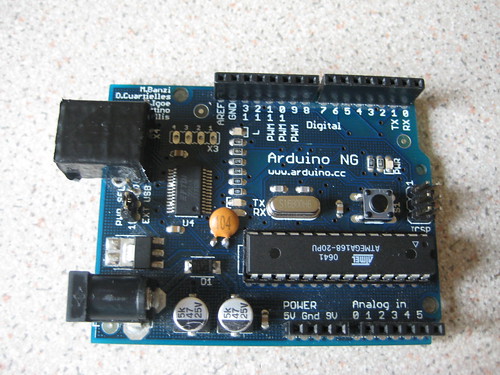
Recently a new Arduino board, the Arduino Diecimila has been released. This board is an updated version of the Arduino NG, which I own. It features a couple of new features, most notably a 3V3 out and an auto reset function. With the NG you needed to press reset to load a new program onto it, and it took 10 seconds to initialize the program when power was turned on, with the Diecimila this is not necessary and it boots up much faster. Normally I’d need to buy a new batch of Arduino Diecimila ATMega168s and boards, but by making some small alterations to the boards, detailed here or here. I went and made the modification to my Arduino NG board as you can see here:

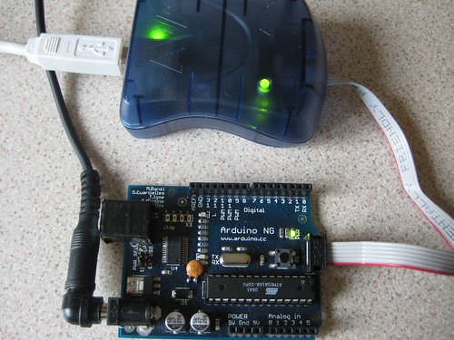
I also needed to upload a new boot loader onto the ATMega168 in order to take full advantage of the 0.1µF capacitor. To do this I needed to connect up the AVR ISP MKII that I also received today. This fitted onto the 2×3 pin header at the rear of the Arduino NG.

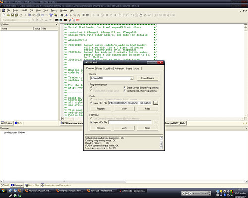
Once it was all connected I need to make a few modifications to the boot loader. I did this using Lady Ada’s instructions here, this ended up looking like this:

This was just after uploading the new boot loader to the Arduino NG. I found that this worked perfectly and I shall be doing the same to the rest of the Arduino hardware that I own. I’m also now aiming to start working more with Arduino.

Now with these improvements to my base Arduino I took another look at my accelerometer project, I’m aiming to get the code finished, all be it in a rough-ish form by the end of the week. Once I’ve done that I’ll be posting here about the hardware changed, aims and the code.


Knowledge Updates

Recently I’ve moved into University. I’m doing a course in Electronic Engineering, and I hope to gain a masters at the end of it.

So far I’m in my 5th week (4rd week of teaching) and I’m finding it very different, but also very interesting. The day is split up into hour blocks, with the first 50 minutes for lectures, and the remaining 10 minutes so that you can rush to the next thing on the timetable. I get 6 hours a week in laboratories messing around with components, and then the rest is theory, and there is quite a bit of that, with me spending about 26 hours a week working. There is on top of that exercises and prep work to be done outside of lectures and labs. That makes it quite intensive as courses go.

I’m living in halls on campus, however there are only 7 people on my floor, 3 girls and 3 other boys. As our floor is none too spacious we have gotten to know each other quite well and enjoy ourselves. I’m a bit new to actually living away from home so things are very different for me, but I seem to be managing.

All this change in scenery has not slowed my electronics. Today I received my latest order from Rapid. This consisted of about 300+ 0.1µF capacitors, 50×2 header pins, a 35A 600V bridge rectifier and an AVR ISP MKII. I bought the 0.1µF capacitors because they are rather ubiquitous in electronics as de-coupling capacitors, they are also used in the Arduino Diecimila, but more about that later. The 50×2 header pins are for in circuit programmers, to go along with the AVR ISP MKII for the new AVR projects that I’m planning. However the 35A 600V bridge rectifier is for an older project, I wanted to see if it could be practically be used in the intended application, or whether it would just be destroyed, unfortunately the intended application is a secret for the moment. The AVR ISP MKII is, unsurprisingly, for programming AVR projects. I also wanted to get it for burning Arduino boot loaders.

Recently a new Arduino board, the Arduino Diecimila has been released. This board is an updated version of the Arduino NG, which I own. It features a couple of new features, most notably a 3V3 out and an auto reset function. With the NG you needed to press reset to load a new program onto it, and it took 10 seconds to initialize the program when power was turned on, with the Diecimila this is not necessary and it boots up much faster. Normally I’d need to buy a new batch of Arduino Diecimila ATMega168s and boards, but by making some small alterations to the boards, detailed here or here. I went and made the modification to my Arduino NG board as you can see here:

I also needed to upload a new boot loader onto the ATMega168 in order to take full advantage of the 0.1µF capacitor. To do this I needed to connect up the AVR ISP MKII that I also received today. This fitted onto the 2×3 pin header at the rear of the Arduino NG.

Once it was all connected I need to make a few modifications to the boot loader. I did this using Lady Ada’s instructions here, this ended up looking like this:

This was just after uploading the new boot loader to the Arduino NG. I found that this worked perfectly and I shall be doing the same to the rest of the Arduino hardware that I own. I’m also now aiming to start working more with Arduino.

Now with these improvements to my base Arduino I took another look at my accelerometer project, I’m aiming to get the code finished, all be it in a rough-ish form by the end of the week. Once I’ve done that I’ll be posting here about the hardware changed, aims and the code.