Posts with «ee - project & practice» label

Oscilloscope Christmas Tree

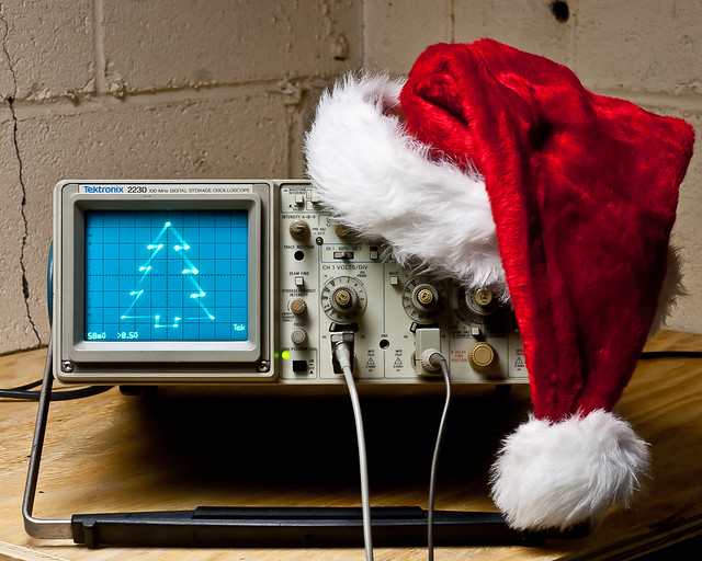
When I was a little kid, my dad worked at Bell Labs. Every year around Christmas, we’d go visit him at work. One memory which has always stuck with me from my holiday visits was seeing a Christmas tree on an oscilloscope. I was pretty amazed by it. Engineers are a funny bunch — they tend to celebrate holidays in the most uniquely nerdy and wonderful ways, just like kids. When I recently acquired a new ‘scope and wanted to familiarize myself with it, I knew exactly what my test circuit was going to be.

In honor of the nameless BTL engineer whose scope scribbling captivated me as a child, here we are. Maybe the same thing will happen for some other kid. There are a lot of holiday parties coming up. You could put this on one of your scopes at work or at your hackerspace, and some other kid will see it, and it’ll fire their imagination too. It looks pretty neat at any rate, and it’s downright fascinating after a few fortified egg nogs.

While I suspect the original was built with 74xx logic circuits, or maybe a couple 555′s (you could easily make a Christmas tree shape by combining triangle (x) and sawtooth (y) waveforms), this one uses an AVR ATTiny2313. (I used my handy BB313 board). You could do this with an Arduino too (that is covered below) — pretty much anything that has an 8-bit timer with dual PWM outputs will do the job. The discussion will apply regardless of the implementation (though the numbers might change).

Before you continue, bear in mind that I assume you already know how to use an oscilloscope: how to attach the probes, adjust the voltage ranges, put it in XY mode, etc.

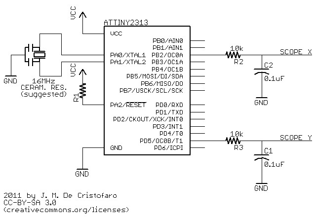
The ATTiny code is here, and this is the schematic for the circuit:

How it works:

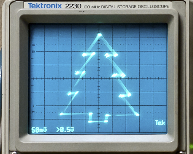
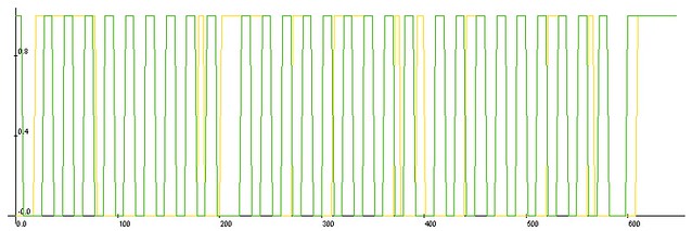
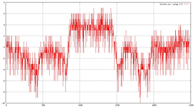
The PWM outputs feed two RC low-pass filter circuits, with a time constant chosen to effectively suppress the jitter from the rectangular waveforms. The PWM outputs (and hence the DC components of the signals) jump from one point in the drawing to the next; in order to actually draw lines to make the tree shape, you have to interpolate between those points. The delay between one ‘drawing’ point and the next has to be chosen to allow the charge/discharge curve of the RC circuit to do the interpolation. You’ll notice in the photo above that the ‘straight’ lines are slightly curved. This is the because the jumps in x don’t quite equal the jumps in y. You’ll also notice that the tree appears a bit crooked. This is the result of the RC curve not settling out completely before the next transition — the voltages never quite get to where they’re supposed to go before they switch to a new value. Personally, I rather like these imperfections — the tree has a hand-drawn quality to it, like a homemade ornament. You could make the lines straighter and the drawing more uniform by using a longer delay, but it will lower the overall refresh rate, resulting in noticeable flicker. How you draw your oscilloscope Christmas tree says a lot about your personality.

The ATTiny’s clock is running off of a ceramic resonator at 16MHz. The PWM frequency is 16MHz/256 or 62.5kHz. The corner frequency of the filter is 160Hz, which is about 8.5 octaves (2.5 decades) below that. I used 10k resistors and 0.1uF caps here — you could also use any other “equivalent” RC combo (100k/0.01uF or 1k/1uF, etc.) If you choose to use a chip with a different clock frequency, then you’ll have to adjust the RC circuit accordingly.

Reducing the capacitor values (or increasing the resistor values) will shift the corner frequency of the filter up, and you’ll start to see the lines get crooked, like resistors in a schematic. These are triangle waves resulting from filtering the rectangular PWM signal. This can look pretty cool too, actually, as below where I switched to 0.022uF capacitors.

Now the tree has needles, and all it took was changing the coefficients of a partial differential equation — easy! (this might be a great way to introduce a kid to the concept of filtering — just sayin’).

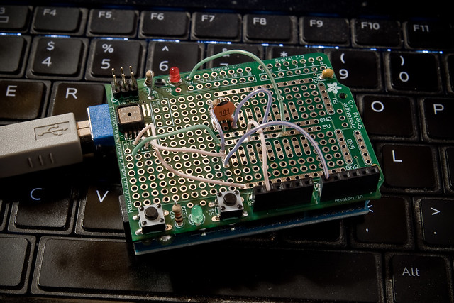
Arduino Implementation:

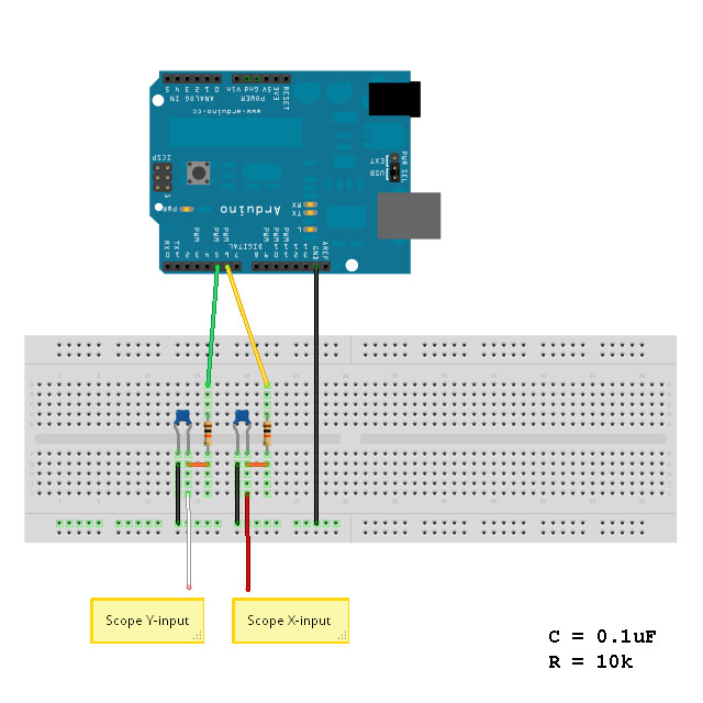
Doing this on an Arduino isn’t much different than using the ATTiny, except that it’s more expensive and instead of a real schematic, you have to read this ridiculous handy cartoon (above).*

The Arduino code is here. It uses no libraries, so all you have to do is extract the folder into your Arduino directory, set up your oscilloscope and load the sketch.

Possible alternative methods:

  • If you really, really want a perfect, orthogonal tree, you can use an R2R ladder or dedicated DAC/soundcard to generate the control voltages.
  • You can get straighter lines if you use a current mirror to feed the RC circuit, thus making it a “true” integrator with a straight-line slope.
  • If you want to increase the refresh rate, you could set an upper limit on the 8-bit timer to a lower value, say 64, and set all your points therein. Note on the ATTiny you’ll probably have to do this using an interrupt from the other timer, but it would give you faster PWM output, which means you can use a smaller filter time constant and thus a higher refresh rate.
  • …or, you could overclock the AVR (you know you’ve always wanted to).
  • As I mentioned in the beginning, you might be able to do something like this with a couple of 555′s generating triangle and sawtooth waveforms. If you get their phases matched correctly and with the right frequency ratio, you could have a pretty nice looking tree!

Be as creative as you like with it — I hope you enjoy making it work for you.

Merry Christmas!

*just kidding — I love Arduino! Buon Natale!


UPDATE – Several folks have done this themselves and written in:

EmbeddedEric did an awesome Frosty the Snowman with his daughters.

aussie_nick did one using a DSO.

Goran did one for the Calgary On-Air Engineers.

Gordon Pearce took it to the next level with animation using sine functions:

Nice!

Arduino I2C Sniffer

I’m working on an I2C project, but I don’t have a sampling oscilloscope and I need to see what the heck is going on, so I put together this quick and dirty I2C sniffer sketch.

You connect two digital pins on the Arduino to the I2C bus lines SDA and SCL, and Arduino ground to I2C ground. The digital pins on the Arduino must be on PORTD, which are pins 0 through 7. It’s probably a good idea to avoid the serial lines, which means you should use any two pins between 2 and 7.

It captures the data (within a certain time window) and then it sends CSV-formatted output to the serial port. You can then take this data and plot it to get an idea of what’s going on on your I2C bus. Naturally, you could expand this to sniff other bus-types, like 1-wire or SPI, provided the signalling rate is low enough. For SPI you might trigger off the SS line. This code samples at about 2Msps on an Arduino running at 16MHz — that figure is derived from the fact that it records approximately 20 samples per 100kbit/s clock cycle.

This code runs a “one-shot” capture, meaning that it only captures data once and then dumps it to the serial port. It starts capturing when it detects the SDA line has gone low. it does not check the SCL line (as a proper start condition detector would).

You can adjust the capture window to suit your needs, though bear in mind that the ATMega328 only has 2k of RAM, so values approaching 2000 may not work so well. A value of 250 is long enough to catch one byte sent over I2C at the 100 kbit/s standard rate. The sampled data is good enough to show you the sequence of events.

If you need very specific, time-aligned data, you should use a logic analyzer or sampling oscilloscope.

For plotting, I recommend LiveGraph, which is super easy to use and runs in Java, so it’s portable.

The code is CC-BY-SA 3.0 and unsupported. Use at your own risk.

Source:

/******************************************************
Arduino I2C Sniffer

2011 J. M. De Cristofaro
CC-BY-SA 3.0
this code is unsupported -- use at your own risk!

connect one digital pin each to SCL and SDA
use pins on PORTD (Arduino UNO/Duemilanove pins #0 - 7)
do not connect to serial pins (0 & 1)!

connect GND on Arduino to GND of I2C bus
*******************************************************/

/** DESCRIPTION **/
/*******************************************************
this code runs a "one-shot" capture, meaning that
it only captures data once and then dumps it to the
serial port.

it starts capturing when it detects the SDA line has
gone low. it does not check the SCL line (as a proper
start condition detector would). 

you can adjust the capture window to suit you needs.
a value of 300 is long enough to catch one byte sent
over i2c at the 100 kbit/s standard rate. the sample
data is good enough to show you the sequence of events,
but little else.

if you need very specific, time-aligned data, you should
use a logic analyzer or sampling oscilloscope.
*******************************************************/

// assign pin values here
const char sda_pin = 2;
const char scl_pin = 7;

// sampling window
const int data_size = 250;

// array to contain sampled data
byte captured_data[data_size];

// housekeeping booleans
boolean captured;
boolean dumped;

void setup()
  {
    Serial.begin(57600);
    pinMode(sda_pin, INPUT);
    pinMode(scl_pin, INPUT);
    captured = false;
    dumped = false;
    Serial.println("Good to go, chief!");
  }

// main loop: waits for SDA to go low, then
// samples the data, then formats and dumps it
// to the serial port.
void loop()
  {
    while(digitalRead(sda_pin)==HIGH) {}
    capture();
    if (captured == true && dumped == false)
      {
        serial_dump();
        dumped = true;
      }
  }

// captures the data on PORTD and stores it in a global array
void capture()
  {
    byte tempdata;
    for (int x = 0; x < data_size; x++)
      {
        tempdata = PIND;
        captured_data[x] = tempdata;
      }
    captured = true;
  }

// reads the data out of the global array, formats it
// and outputs it to the serial port.
void serial_dump()
  {
    byte temp;
    Serial.println("sample, sda, sck");
    for(int x = 0; x < data_size; x++)
    {
      if (x<10) { Serial.print("0"); }
      if (x<100) { Serial.print("0"); }
      Serial.print(x);
      Serial.print(",     ");
      temp = bitRead(captured_data[x], sda_pin);
      if (temp == 0) { Serial.print(0); }
      else { Serial.print(1); }
      Serial.print(",   ");
      temp = bitRead(captured_data[x], scl_pin);
      if (temp == 0) { Serial.println(0); }
      else { Serial.println(1); }
    }
  }

Hacking An Industrial CNC Lathe, Part I: Intro

Hitachi-Seiki 3NE-300 Lathe, circa 1980

I’m currently taking some mechanical engineering classes at County College of Morris (CCM) in Randolph, NJ. Among the equipment in the machine shop is this mean, green Hitachi-Seiki CNC Lathe, a neat piece of industrial equipment from the late 70′s/early 80′s.

Currently, there are two ways to program the machine. You can program it manually, by entering in codes on the keypad:

3NE-300 control panel

-OR- you can get your Jacquard on and write a program on punched tape:

FANUC punched tape reader

Naturally, for ease of use, the punched tape reader is on the back of the machine. *sigh*

Fortunately, there is a third way to get program code into the controller. This is via an RS-232C port:

Serial port: a DB-25 RS-232-C port and an MR-20 "HONDA" connector

The obvious question is: why not just hook the serial port up to a computer? Well, due to the logistics of the shop, it’s not feasible to have a computer in the immediate vicinity of the machine. In order to hook it up to the nearest computer, the required cable would be at least 25 feet long. In practice, this translates to a 600-baud signaling rate, as there is a lot of EM interference in the shop, due to motors, fluorescent lights, etc. It’s much easier to simply have a small “black box” that can load the program from modern media like an SD card.

My plan is to build a circuit based around an Arduino, which will read an NC file (ASCII text) from an SD card and send it to the machine over the serial port. I plan to use the following hardware:

  • Arduino Mega – the brains of the operation. To be honest, I probably won’t need the extra pins of the Mega, but with the full SD library, the serial library and the extensive menu system I plan to write, I need the extra program memory.
  • LCD with Adafruit i2c/SPI backpack – for the display (file menu, load progress, etc.)
  • Adafruit Logger Shield – for reading from and writing to the SD card.
  • CuteDigi RS232 Shield – not entirely sure about this one yet. I may just get an Adafruit protoshield and wire up a DB-25 port to it.
  • Hammond 1550D enclosure – with milled openings for the SD card, LCD and buttons.

The controller for the lathe is a FANUC 6T-B. While rather primitive by today’s standards, in it’s day it was a top of the line industrial controller, and FANUC is still the standard. It’s pretty much indestructible too, which is a bonus, because it means I won’t end up scrambling the brains on a $20,000 piece of equipment.

More to come as I work on this project over winter break. I’m hoping to get the electronics soon and start work on the menu and input systems. By the time I get back to school in January, it’ll (hopefully) be ready to interface with the FANUC controller.

A Brief Essay About the Benefits of Open-Source Hardware #openhardware

Didn't have a photo to go with this article, so here's a picture of a cat with an Arduino

The Other Benefits of Open-Source Hardware

Lots of people have been talking about (and questioning) the economic value of open-source
hardware. The most frequent question/criticism is that OSH facillitates the ripping off of the
original designer. That is, they publish their work openly and then someone else takes this work,
produces a product, and sells it. None of the money from this sale goes to the original designer.
In the case of less scrupulous manufacturers, no attribution is cited and all identifying marks
are removed from the product. Under these conditions, it would be rather difficult to take legal
recourse, particularly if said manufacturer is based somewhere overseas.

The argument itself is quite valid — the above scenario could happen, and I know for a fact that
it does happen. And there’s really not a damn thing you can do about it. It happens to people
whose work is protected by copyright too, if that makes you feel any better.

The problem I have with the argument above is that it’s only valid when the hardware is being
sold (or intended to be sold) commercially. This represents one way to make money from your
work, but it’s not the only way. The work itself has value too.

In her keynote address at the Open Hardware Summit, LadyAda pointed out that one of the
prime benefits of doing open hardware is that it makes you a better engineer. I’m inclined to
agree. From this standpoint, the OSH community is sort of a ‘peer-review’ journal with a very
low barrier to entry (can you put it on the internet?) and worldwide exposure (make something
cool and the blogs will pick it up). Within a week you’ll receive LOTS of peer review. Some will
be positive, much of it will be negative. Most of the negative stuff you can ignore (see rebuttal),
but a portion of the negative will be constructive, and that’s the part you should pay attention to.
This instant feedback is usually in the form of blog comments. When people really start looking
at what you’ve done and begin making changes, adding things, or using it in projects, that’s the
real peer review. It’s also the most rewarding part.

But how can this make you money, or at least help you in your professional life? The answer
is simple: it raises your profile, gets you props, and gives you cred. There are plenty of people
who bank on their own rep and get paid. That’s basically what you’re doing when you send out a
resume or CV — it’s all about what you’ve done and how you did it.

In the terms of this discussion, you get cred for three things: good design, great docs, and
actually completing the project. Good design and great documentation are fairly obvious. The
last one sounds ridiculous, but it’s not. I have no actual data to back this up, but I’m willing to bet
that the ratio of unfinished vs finished projects in the world at any moment is about 100:1, and
I’m probably being generous.

Lots of people have great ideas every day. Some people act on them. And then there are the
proud, rare few who actually finish what they’ve started. It’s not easy, particularly if you have
other things to do. Still, if you can take a project from conception through design to building and
testing, and then document the hell out of it and put it out into the wild in a finished and working
state, you get insane cred. And not just among the relatively few people who see it on a blog
and comment: “cool project!” (p.s. god bless those people).

Let’s say two engineers (A & B) want to apply to graduate school. The only project Engineer A
has on her CV is her senior project, which doesn’t work the way it should and is only minimally
documented (which pretty much describes every senior engineering project ever).

Engineer B is very similar to A — she has the same grades and a similar ‘almost working’ senior
project. But B also put together a neat little open-source hardware project on her own time, fully
tested, with complete documentation. It’s not as complex as her senior project, but it actually
works. She puts this on her CV, along with a link to the project. She also sends an email to the
department chair telling this person about her project, and mentioning that she might be thinking
about applying to grad school at his prestigious university.

If you were the department chair, who would you more like to admit into your program? The
person who is just like every other applicant, or the person who has shown the initiative and
ability to take a project from start to finish? I’m not dumb enough to make some guarantee that
doing OSH will get you into grad school, but it definitely can’t hurt you.

It’s very similar in the professional world. You have your resume and references just like
everybody else. The thing that will make you stand out is the self-motivated and fully realized
work you’ve done on the side by yourself. The demonstrated ability to document your projects
comes into play here too. Engineers hate documentation. HATE IT. Because it sucks. But
it’s a necessary evil — you can’t (or at least you shouldn’t) sell a product to a customer without
documentation. Engineers who can write docs are a valuable asset to any company — in fact,
they are critical, and always in short supply.

The open-source hardware community gives you the opportunity to “publish” your work and show off your skills,
be recognized for them, and eventually be rewarded for them. The reward may or may not be monetary,
but there’s plenty of good karma and experience to be had, and lots of cred.

End.

If you want to discuss this post, or tell me I’m wrong and call me names, you can do that here.

Barometric Sensor testing with Arduino

Freescale MP3H6115A baro sensor on Arduino protoshield.

bad data

good data

Click on the pictures for more info.