Posts with «arduino» label

Almost ready to order

I got a reply from Custom PCB:

Yes, Eagle generates lines below 6 mils all the time. It is always up to the PCB manufacturer to fix it up to their minimum line width. So we don’t check against that because it is not something that designers can easily fix with their PCB software. But we do warn customer about silkscreen problems if their text is too small to be legible after increasing the line width to 6 mils minimum.

I just finished re-laying out the constricted ground wire. The narrowest constriction is 0.25″ now, but only for about 0.1″. The thermal calculator  can’t handle constrictions well—it wants to analyze under the assumption of an infinitely long wire 0.25″ long:

The trace width calculator uses empirical formulas based on long traces with no special heat sinking. … The trace width calculator is more geared towards long traces. Short traces with heat-sinking to planes do not get as hot.

It predicts a 30ºC temperature rise, but since I have a lot of heat sink nearby, I think that the temperature rise will be well under the usual 10ºC design guideline.

I also checked my vias with http://circuitcalculator.com/wordpress/2006/03/12/pcb-via-calculator/, which says that  27 mil holes with 1mil plating 62mils long should have a resistance of about half a milliohm and be able to carry about 3.4 Amps, so 5 such vias should be enough.  I have 11 or 12, which should be plenty.

Figuring out minimum trace width for a given voltage drop or power dissipation with http://circuitcalculator.com/wordpress/2006/04/20/find-pcb-trace-width-based-on-power/ might be useful in some other applications, but I’m less concerned about IR voltage drop than I am about temperature rise.

So, after I’ve gotten some sleep and had a chance to see if Gabriel or Steve can check my design, I think I’ll be ordering from CustomPCB.


Filed under: Hexmotor H-bridge board, Printed Circuit Boards, Robotics Tagged: Arduino, motor controller, Printed circuit board, trace width

More on PC boards

I got back the results of the free check of the design rules from FreeDFM.com that I mentioned in my earlier post, and there are a lot of problems.

First, the sfe-gerb274x.cam script from SparkFun included the Dimension layer in the top copper, but this generates traces that are far too thin (0.1 mil) to be made.  The outline of the board does not belong on this layer.

Second, the Adafruit component for the Arduino, that labels the Arduino pins used 3 mil strokes, but the minimum stroke width for 4pcb.com’s silk screens is 5 mils, so there were 4103 violations.

I fixed the script that generated the top copper file so that it didn’t include the Dimension layer, and went through some of the libraries fixing the fonts so that the 0.04″ high letters has a stroke/height ratio of 13% and the 0.05″ high letters had a stroke/height ratio 10%, meeting the minimum silkscreen requirements. I resubmitted the design to FreeDFM and got

Congratulations!
No DFM problems were found on your board!

Show Stoppers
We Found None!
Problems Automatically Fixed by FreeDFM
We Found None!

They also provide some nice pictures of the layers as pdf files, so maybe I don’t need a Gerber file viewer after all (though the separate PDF files don’t give me any clues about possible misalignment).

I’ve not decided for certain whether I’ll go with 4pcb.com for my fabrication, but the fact that I was able pass their design rule checks (and the positive recommendation for them that I got from someone who supervises a lot of student PC board designs) is encouraging. The minimum order of $132 (which would give me 5 copies of the board) is a little daunting for a first attempt, as I’m sure I messed up something.

Yep, I sure did. In a comment on my earlier post Mylène gave me a pointer to a trace width calculator, which I used to figure out whether I had made my ground line fat enough.  The answer is “No!” If I use the cheapest fab lines, I get 1oz/ft2 of copper, which the calculator estimates would heat up 40ºC in the most constricted spot on my board.  So I guess I have to push things around until there is enough room for another ¼” of wire there.  Good to catch that now, rather than after fab!

Advanced Circuits does have a cheaper “bare bones” option, but it does not include a solder mask.  I don’t think I want to try soldering even 0.1″ spaced pads without a solder mask, as I’m clumsy enough to have trouble with solder bridges even when there is a mask.

I also looked at Olimex, which claims very low prices (30€ a board for 1–4 boards), but I was turned off somewhat by the low-quality of their web site and the big announcement:

Note: we are in summer vacation 1-31 of August.
ALL PCB files sent after July 26th will be proceed in September.

I didn’t do it justice here: the announcement fills the screen on their site.  Since I want to work on this primarily in August, I’m not willing to take a chance on their being shut down for the month when I need the boards.

Olimex does take Eagle board files directly, doing their own conversion to Gerber and drill files.  This could be a nice advantage for someone who doesn’t want to bother with the Gerber files.  Now that I have a script that does the right thing, though, it should not take me much effort to do the conversions myself, so this advantage is small.

Perhaps more important is that they release their design rules as Eagle dru files, so you can do your checking as you do your layout.  I downloaded both their rule sets (the 8-mil and the 10-mil) and found that my design fails both.  Again, the problem is with silkscreen stuff, but not the line thickness—the silkscreen outlines of some of the parts I use comes too close to the solder masks for them.  I had a few problems with that even using the default design rules, but I fixed those by editing the package outlines.  The Olimex rules require an even larger clearance, and there are too many different drawings involved, so I’m not willing to take the time to tweak everything to fit Olimex’s fussy rules, despite the low price.

Custom PCB offers low prices and takes Eagle files (or Gerber files, of course).  I think I could get 4 boards for $90 from them, including shipping from Malaysia, but I’m still waiting for the official quote. I think I may fail their design-rule check, though, as they specify a minimum of 6mils for silkscreen lines on their design-rule page.  I’d have to redo a lot of lines to meet that spec!  And I’d have to write (or find somewhere) a set of Eagle design rules that match their requirements, since they have slow turnaround on checking for manufacturability (a day).  They sent e-mail saying

“We have reviewed your design and it looks good for production.  Total cost for 4pcs with Soldermaks & Silkscreen is USD 72.00 + USD 15.50 shipping to USA.”

If they are willing to accept 5 mil silkscreen instead of 6mil, this may be the way to go!  I’ve sent them an e-mail query about their design review—whether they neglected to check the silkscreen or if their minimum acceptable line width has changed.

PCBExpress has a minimum price of $390 (for 2 boards this size).

PCB unlimited has a minimum of $230 (which would get 2 boards) for the “quickturn” pricing and $260–280 for their overseas fab (which would get 1–10 boards).

PCB Universe has $127 (including shipping) for a 4-board lot up to $229 for 10 boards (beyond that number, their standard pricing is supposedly cheaper).  They have 5mil minimum space and lines, which my design easily meets.  Their pricing is similar to 4pcb.com, but without the service of the free design-rule check.

Prototype PCB quoted me $229 for 3 boards.


Bottomline:  If CustomPCB can handle the 5mil lines on the silkscreen, then I think I’ll give them a try.  Otherwise I’ll probably go with 4pcb.com


Filed under: Hexmotor H-bridge board, Printed Circuit Boards, Robotics Tagged: Arduino, motor controller, Printed circuit board, robotics

Designing a printed-circuit board

One of my projects for this summer is to learn to do printed-circuit board design.

Some of my constraints:

  • The software must run under Mac OS X.  I’m not getting a Windows machine.
  • The software must be cheap (or free).  This is a hobby, not a profession, and I’m not willing to pay the sort of prices that tools like Cadence cost.
  • The printed-circuit boards have to be cheap.  There is not much point in designing something if I don’t get it made, and I don’t want to spend huge amounts on designs that may turn out to be awful.

After looking around for a while, it seems like there is really only one choice for Mac users: the Eagle software from CadSoft.  (There may be some other choices in a few years—but none of the other Mac products I found seemed to be widely accepted.) There is a slightly crippled freeware version of Eagle (only 2 layers and 8cm × 10cm max size) which should meet my needs fine.

For the past several days, I’ve been learning to use Eagle and laying out a board to have 6 motor channels, each with up to 2.5A at 12v.  Some of the design is overkill (I could go to 36v by replacing the capacitors with higher voltage ones, and I could deliver up to 5A per motor, as long as I don’t exceed 15A total).

Eagle has been a struggle to learn to use—the user interface feels like it was frozen in the 1980s, with really awkward multi-click actions for everything.  The software reminds me a lot of  Magic, the free VLSI layout software written around 1982, except that Magic had a much nicer user interface.

All the functionality seems to be there in Eagle, but is hard to find—you really need to consult the 327-page manual a lot. Normal actions are not done in normal ways.  For example, to operate on a group of objects, you have to click on the tool you want to use, then on the group tool, then click-and-drag to select the group, then right-click to perform the action on the group—about twice as many operations as on a modern interface, and in a non-intuitive order.

When I say “all the functionality seems to be there”, I’m using a rather generous definition.  For example, if you make a mistake when defining a new packaging variant for a part in the library, there is no way to undo it.  You can start over from a backup file or create a new part with a different name and do all the work over.  There is no universal “delete” option (say by right-clicking to pop up a menu) that works for variants, and the command-line commands don’t allow removing packages from devices.

Copying subcircuits is possible (something I needed to do to make 6 identical H-bridge circuits), but you have to be careful—if you name any of the nets, it will short the nets together, since it has no way to generate unique names other than the automatic ones it generates.

It would probably cost a lot to redo the user interface into something like a modern program, and the number of engineers and hobbyists using PCB-layout programs is probably not a big enough market to justify the cost.  I am glad that it was a free version, though, as I would have felt really annoyed if I’d paid money for such an incredibly awful interface.

Despite the struggles to learn Eagle, I think I have finally gotten a design done.  It uses the whole 8cm × 10cm area.  At first, I had an incredibly difficult time packing everything in (and the freeware version of  Eagle doesn’t let you unplace things once they’ve been placed). After making some circuit design changes (removing the superfluous freewheeling diodes, for example, since they are included in the H-bridge chips I chose) and some packaging changes (using 3.5mm pitch screw terminal blocks, instead of 5mm pitch ones), managed to end up with room to spare.

At first I did tried doing all the routing by hand, then discovered the follow-me single-net router, then the autorouter.  It turns out that autorouter had no trouble completing, but I ended up hand-routing all the high-current wires anyway.  I didn’t see any way to tell Eagle which parts of the GND net needed to be fat wires and which could be skinny wires, for example.  A net has only one width, and the design-rule checker checks that width throughout.

Some little gotchas included that the default drill size for vias is smaller than the default minimum drill size for the design rule check.  Luckily I did a design-rule check very early, before I’d done much routing, so I could increase the drill size for the vias without having to rip everything up and start over.

Actually, I ended up doing the whole design almost from beginning to end three times, because of design modifications (getting rid of the freewheeling diodes, for example, or deciding to add headers for servo outputs).

My design now meets the default design rule checks provided by CadSoft, so it is time to see about getting it fabricated.  I looked into a few different PC board houses.  The one that the “PCB Quote” button in the software connects you to is ridiculously expensive (so I’m not even going to provide a link to them).  One that I’ve had recommended to me is Advanced Circuits at  http://www.4pcb.com, which has very low pricing, but does not accept Eagle files.  You have generate Gerber RS247X files for each layer and Excellon drilling files.

Eagle is capable of doing this, but once again the interface is incredibly clunky—luckily there are some scripts that automate the process, if you can figure out how to make them work.  I started working with one from SparkFun, described in the SparkFun Eagle tutorial, but it turned out not to work with the latest version of Eagle.  I had to compare it with the “cam” scripts provided with Eagle to see that the output now needs to include “%N” to generate the file names.

Once I got that sorted out, I could change the layers that were specified for the top silkscreen (I had designed the board to use tPlace, tNames, and tValues, while SparkFun just used tPlace) and generate the Gerber and Excellon files.

I’ve not yet figured out what Mac OS X tools there are for viewing Gerber files, to check to see if the conversion worked, but Advanced Circuits has a Free File Check option.  I submitted the files there and expect to get a feedback email either in half an hour or tomorrow.


Filed under: Hexmotor H-bridge board, Printed Circuit Boards, Robotics Tagged: Arduino, motor controller, Printed circuit board, robotics

What is "Minimalduino"?

I started working on the "minimalduino" design as...
  1. a minimal hardware design for an Arduino-compatible board. At heart, it is very similar to the Dorkboard, but
  2. designed to match the form factor of the "official" Arduino boards so users can benefit from the many, many shield boards designed to fit on top. While (awesome) boards like EMSL's Diavolino are also low-cost and shield-friendly, I wanted to explore
  3. optional hardware configurations, with different power connector options (pin headers, JST connector, barrel jack, screw terminals, or mini USB jack), 5V and 3.3V power regulation and optional voltage switching and regulator bypassing, and options for crystal and caps or a resonator. I also wanted to have
  4. better shield-friendliness by placing LEDs (power and D13) and the reset switch (side switch or top switch) at the edges of the board, and lastly, I wanted the board to be
  5. single-sided, home-etchable with wide traces and minimal jumper wires. There is still work to be done to reduce jumpers, but it improves on the the S3V3 "Severino" board which doesn't match up size-wise (it's bigger), the standoff mounts don't match, and it uses a DB9 serial connector instead of the now widespread FTDI USB-serial breakout cable.

Scratch and the Arduino

Small S4A (Scratch for Arduino) program that detects when a button is pressed. I used a pull-up resistor, so pressing the button pulled the signal low. Since that is a very standard circuit, I object somewhat to the "Sensor pressed" terminology. It should say either "Sensor Digital1" (since the value is Boolean) or "Sensor Digital1 high"—the "pressed" word is misleading.

There is a project now that combines two of my favorite tools for teaching about computers: Scratch for beginning programming and Arduino for beginning embedded systems and microcontrollers: Citilab – Projecte Scratch. The project appears to be from Spain, as the main page of the site is in Catalan, though the Arduino page is in English.

The idea is a simple one: the Arduino is loaded with a standard program that interchanges information with the Scratch program via USB every 75 msec. The I/O pins of the Arduino have a standard configuration:

The configuration offers 6 analog inputs (analog pins), 2 digital inputs (digital pins 2 and 3), 3 analog outputs (digital pins 5, 6 and 9), 3 digital outputs (pins 10, 11 and 13) and 4 special outputs to connect Parallax continuous rotation servomotors (digital pins 4, 7, 8 and 12).

They had to modify Scratch a little to add blocks for the I/O (similar to the official Scratch blocks for the “Scratchboard” which is not nearly as versatile as the Arduino). It would be nice if the S4A modifications made their way into the official version of Scratch, as the Arduino and Scratch communities are natural allies in making computer science and computer engineering more accessible to non-specialists.

There are some mistakes they made. For example, they put all the Arduino blocks with the “motion” blocks, though it would have made more sense to have a new page of blocks (or to have spread them between the motion and sensing pages).

They also refer to digital inputs pin 2 and 3 as Digital1 and Digital2, and to Analog pins 0 through 5 and Analog1 through Anlaog6. I think that they need to make their Scratch programs consistent with the labeling on the Arduino board! The digital outputs are correctly labeled 10, 11, and 13, but they have separate blocks for On and Off, which is not as nice as a single block that can set the digital output to a Boolean (though Scratch would have to have constants <True> and <False> for that to work well).

I’ll be sharing S4A with the robotics club, as it looks like a fun thing to play with, even if there are some minor design flaws.


Filed under: Scratch, Software Tagged: Arduino, Scratch, software

Scratch plus Arduino

Small S4A (Scratch for Arduino) program that detects when a button is pressed. I used a pull-up resistor, so pressing the button pulled the signal low. Since that is a very standard circuit, I object somewhat to the "Sensor pressed" terminology. It should say either "Sensor Digital1" (since the value is Boolean) or "Sensor Digital1 high"—the "pressed" word is misleading.

There is a project now that combines two of my favorite tools for teaching about computers: Scratch for beginning programming and Arduino for beginning embedded systems and microcontrollers: Citilab – Projecte Scratch.  The project appears to be from Spain, as the main page of the site is in Catalan, though the Arduino page is in English.

The idea is a simple one: the Arduino is loaded with a standard program that interchanges information with the Scratch program via USB every 75 msec.  The I/O pins of the Arduino have a standard configuration:

The configuration offers 6 analog inputs (analog pins), 2 digital inputs (digital pins 2 and 3), 3 analog outputs (digital pins 5, 6 and 9), 3 digital outputs (pins 10, 11 and 13) and 4 special outputs to connect Parallax continuous rotation servomotors (digital pins 4, 7, 8 and 12).

They had to modify Scratch a little to add blocks for the I/O (similar to the official Scratch blocks for the “Scratchboard” which is not nearly as versatile as the Arduino).  It would be nice if the S4A modifications made their way into the official version of Scratch, as the Arduino and Scratch communities are natural allies in making computer science and computer engineering more accessible to non-specialists.

There are some mistakes they made.  For example, they put all the Arduino blocks with the “motion” blocks, though it would have made more sense to have a new page of blocks (or to have spread them between the motion and sensing pages).

They also refer to digital inputs pin 2 and 3 as Digital1 and Digital2, and to Analog pins 0 through 5 and Analog1 through Anlaog6.  I think that they need to make their Scratch programs consistent with the labeling on the Arduino board!  The digital outputs are correctly labeled 10, 11, and 13, but they have separate blocks for On and Off, which is not as nice as a single block that can set the digital output to a Boolean (though Scratch would have to have constantsandfor that to work well.

I’ll be sharing S4A with the robotics club, as it looks like a fun thing to play with, even if there are some minor design flaws.


Filed under: Scratch, Software Tagged: Arduino, computer science, education, programming, robotics, Scratch

Data Acquisition

One of the science-teacher blogs that I read has recently discussed using an Arduino for data acquisition: The DAQ-ness Monster « Science Learnification.

I’ve not played with the Arduino much that way, but I do have a 3-axis accelerometer, the ADXL335 from Analog Devices, on a breakout board from Adafruit Industries.  This accelerometer has analog readout, so I connected the three X, Y, and Z pins to analog pins 0,1, and 2 of the Arduino, and powered the breakout board from the Arduino 3.3 volt supply.  I also sent the 3.3 volt input to the AREF pin of the Arduino so that the I could use “ratiometric” measurements.  The ADXL335 is designed so that 0g acceleration is mid-scale, so using the same voltage for powering the chip and for the Arduino AREF input means that 512 is 0g and the scaling is approximately 1g for each difference of 100.  It turns out that the calibration is not perfect (no surprise there), so you can improve the measurements by tweaking the offset and scaling for each axis separately.  I did this manually for my code, and the results are only good to about 1%.

I should be able to do better if I write a calibration program on my laptop that gathers results from the Arduino and tries to optimize the magnitudes of the reported acceleration vectors to be one.  If the accelerometer is held steady in several different orientations, this should auto-calibrate.

I wrote a little program that measured the X, Y, and Z values 1000 times, averaged them, and sent the average over the USB line to my laptop.  I’ve put the code on-line at https://gist.github.com/1054649  Each of the measurements takes about 3.3 msec (about 1msec per DAC reading)

Limitations of the Arduino as a data-acquisition device:

  • Only 6 analog inputs
  • Only 10-bit resolution
  • All 6 channels on same scale, and input must be between 0 and a single reference voltage (3.3v for the setup I used).
  • No faster than about 1msec/sample (so don’t try to collect audio or video data)

UPDATE 8 October 2011.  I’ve just found out how to put code into the blog itself, so here it is:

// Accelerometer (ADXL335) test
// Kevin Karplus
// 29 June 2011

void setup()
{
  analogReference(EXTERNAL);   // essential if you are going to connect to AREF
  Serial.begin(115200);
  Serial.println("setup");
}

// I used wires to connect the breakout board to 
// three analong inputs, 3.3v, and ground.
// I also connected the AREF input of the Arduino to 3.3v

const int Xpin=2;
const int Ypin=1;
const int Zpin=0;

const int num_to_sum=1000;
const float xscale = 0.0098/num_to_sum;
const float yscale = 0.0097/num_to_sum;
const float zscale = 0.0099/num_to_sum;

const int zero_x = 500;
const int zero_y = 506;
const int zero_z = 511;

long xsum,ysum,zsum;

void loop()
{
  unsigned long startTime=millis();
  xsum = ysum = zsum = 0;
  for (int i=num_to_sum; i>0; i--)
  {    
     xsum += analogRead(Xpin) -zero_x;
     ysum += analogRead(Ypin) -zero_y;
     zsum += analogRead(Zpin) -zero_z;
  }
  Serial.print(millis()-startTime);
  float x=xscale*xsum;
  float y=yscale*ysum;
  float z=zscale*zsum;
  Serial.print(" X=");
  Serial.print(x);
  Serial.print(" Y=");
  Serial.print(y);
  Serial.print(" Z=");
  Serial.print(z);
  
  Serial.print(" total=");
  Serial.println(sqrt(x*x+y*y+z*z));
}


Filed under: Accelerometer, Data acquisition, Robotics, Software Tagged: accelerometer, Arduino, data acquisition, robotics

3-Digit 7-Segment Display With an SAA1064


Working on the grinder timer project, I built out a basic circuit (EAGLE .sch) with an NXP SAA1064 and resurrected a test sketch (Arduino .pde) for it. The SAA1064 works beautifully for driving common anode 4-digit 7-segment displays with constant current per segment, from 3 to 21 mA in 3mA increments; in this case I'm only driving three digits since that's what the design calls for.

There are two buttons in the test sketch (on D10 and D11), the first to change count modes (seconds, tenths, hundredths, hex, and "chase") and the second to cycle through the seven current settings.

This schematic is identical to one I did a board layout for with an SO24 package chip, but for some reason those boards didn't work; maybe something in manufacture or assembly bridged pins somewhere. I'll redo the layout and see what happens, with vias further from pads.

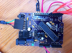
Minimalduino 105: Nice!

I built out one of the "V.105" boards I got a few weeks ago from the DorkbotPDX PCB order, and it works beautifully, almost identical to the version 107 I posted files of, with "5V/3.3V" voltage and "FTDI/IN" power selector switches. I mounted a mini USB socket and a 7805 regulator, in addition to the barrel jack for power in.

I've gone to whole number versioning btw, no need for "always under 1" versioning or major/minor versions, and if I need to go higher than 999 (huh?!), I can just use four digits.

Top and bottom labeling came out great, including the Open Hardware logo, though the letters mush together a little. Also, the "FTDI" header label didn't print at all, maybe there's a problem having two "FTDI" text labels.

One issue is that the drills for the main female headers are smaller than those on versions 89 and 97 boards, even though they use the same parts in EAGLE! I'll check the parts and maybe swap them out. That's a bummer-- I had to drill them all out to mount the headers, which ripped some of the pads off the fiberglass, but thankfully they stayed connected to the traces.

Minor edits for the next version:
  • Move the power input components to give electrolytic capacitors more room to accomodate shorter/fatter ones or taller ones mounted horizontally. As it is, the 100uF cap at the input is jammed between the .1uF cap and the barrel jack. [done]
  • Rotate LED's so they can be mounted horizontally for better side viewing when using a shield. [done]
  • Add heat sink polygon and vias under the 7805 tab.
  • Fix the Sparkfun mini USB through-hole part: its outline is on the bPlace layer, not tPlace where it belongs. Or just use a different part. [done]
  • Check female header drill diameters.
  • Add 2-pin header at the reset button to make it easier to add a remote panel-mounted reset button. [done]
  • Round the corners; looks nice on the Freetronics boards. Also check Uno outline and drills to make sure things are lined up right. [done]
I'm pretty happy with this for now though-- I have plenty of cheap, homemade, 5/3.3V-switchable Arduino-compatible boards to work with!

BlinkM Cylon mkII

For Maker Faire this year I made a second version of my BlinkM Cylon: BlinkM Cylon mkII. This is not a very cost-effective way of getting a Cylon effect. It however is a good way of showing how to wire up multiple BlinkMs with a long cable, using our new WireM cabling kit for BlinkM. And unlike normal Cylon circuits, this has full RGB color effects and gradual fading.

Here’s a quick video showing it in action.

BlinkM Cylon mkII consists of: - 13 BlinkMs (one for each of the tribes of Kobol) - one WireM cabling kit for BlinkM, consisting [...]

Todbot 30 May 07:32
arduino  blinkm