Posts with «arduino» label

Fixing Apple TV’s Terrible UI

Despite Apple’s unfailing dedication to UI, they still sometimes manage to put out some stinkers. The latest of these is the ‘keyboard’ for the search interface in the Apple TV. It’s an alphabetical keyboard, laid out in a square with the obvious frustration that goes along with that terrible idea. [Lasse] was frustrated with this design and realized searching anything with the Apple TV IR remote is a pain. His solution was to build his own version of the Apple TV remote with a web interface, powered by an Arduino.

Inspired by the Apple Remote Arduino Shield we featured a few years ago, [Lasse] stuck an IR LED int the pins of Arduino with an Ethernet shield, current limiting resistors be damned. The web UI is the innovative part of this build. He’s hosting a simple website on the Arduino that allows him to type – with a real keyboard – a search query into the website, and have the Arduino take care of moving the Apple TV cursor around to select each letter.

The web UI has all the features found on the Apple TV remote, including the swipe gestures, and has a really slick brushed metal texture to boot. You can check out the video of [Lasse]‘s project typing text into an Apple TV hilariously fast below.


Filed under: Arduino Hacks, macs hacks

A Virtual Cane for the Visually Impaired

[Roman] has created an electronic cane for the visually impaired. Blind and visually impaired people have used canes and walking sticks for centuries. However, it wasn’t until the 1920′s and 1930′s that the white cane came to be synonymous with the blind. [Roman] is attempting to improve on the white cane design by bringing modern electronics to the table. With a mixture of hardware and clever software running on an Android smartphone, [Roman] has created a device that could help a blind person navigate.

The white cane has been replaced with a virtual cane, consisting of a 3D printed black cylinder. The cane is controlled by an ATmega328 running the Arduino bootloader and [Roman's] code. Peeking out from the end of the handle is a Maxbotix ultrasonic distance sensor. Distance information is reported to the user via a piezo buzzer and a vibration motor. An induction coil allows for charging without fumbling for tiny connectors. A Bluetooth module connects the virtual cane to the other half of the system, an Android phone.

[Roman's] Android app runs solely on voice prompts and speech syntheses. Navigation commands such as “Take me to <address>” use the phone’s GPS and Google Maps API to retrieve route information. [Roman's] app then speaks the directions for the user to follow. Help can be summoned by simply stating “Send <contact name> my current location.” In the event that the user drops their virtual cane, “Find my device” will send a Bluetooth command to the cane. Once the command is received, the cane will reveal its position by beeping and vibrating.

We’ve said it before, and we’ll say it again. Using technology to help disabled people is one of the best hacks we can think of. Hackaday alum [Caleb Kraft] has been doing just that with his work at The Controller Project. [Roman] is still actively improving his cane. He’s already won a gold medal at the Niagara Regional Science and Engineering Fair. He’s entered his project in several more science events, including the Canada Wide Science Fair and the Google Science Fair. Good luck [Roman]!


Filed under: lifehacks, misc hacks

Add long-distance connectivity to your Arduino with the CATkit System

Introduction

Have you ever wanted to connect your Arduino to sensors or other devices but over a long distance? And we don’t mean a few metres – instead, distances of up to 100 metres? Doing so is possible with the CATkit system from SMART greenhouse.

This system is a combination of small boards that are connected between your Arduino and external devices using CAT5 networking cable, giving a very simple method of connecting devices over distances you previously thought may not have been possible – or have used costly wireless modules in the past.

The maximum distances possible depend on the signal type, for example:

  • analogue signals up to 100 metres (with a 0.125 V drop)
  • 1-wire signals (ideal for DS18B20 temperature sensors) up to 75 metres
  • SPI bus up to 50 metres
  • I2C bus up to 35 metres
  • Serial data at 9600 bps varies between 50 and 100 metres

In principle you could also use this with other development boards that utilise the Arduino Uno shield form-factor and work with 5V – so not for the Arduino Due, etc. For more information check out the .pdf documentation at the bottom of this page.

How it works

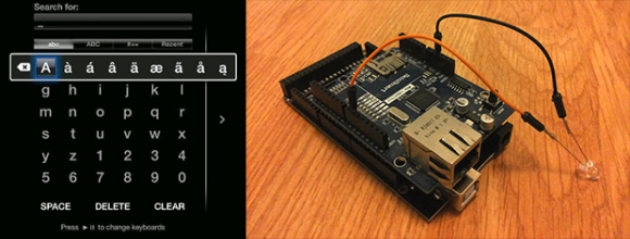
For each system you need one CATkit Arduino shield:

… and one or more Kitten boards. These are both inline – in that they can “tap in” to a run:

or have one RJ45 socket for installation at the end of a cable run:

Note that the inline Kitten has male pins for the breakout, and the end unit has females. These units are available in kit form or assembled. You then use the network cables between the shield and each Kitten, for example:

Each Kitten can distribute six signals, and up to three can be connected to one CATkit shield. These three distribute analogue pins 0~5, digital pins 0~5 and 6~11 respectively. You can also introduce external power to the CATkit shield and the onboard regulator will offer 5V at up to 950 mA for the power bus which can be accessed from the inline or end Kitten boards. This saves having to provide separate 5V power to devices away from the Arduino, and very convenient for sensors or remote I2C-interface displays.  

Using the CATkit system

If you have the units in kit form, assembly is very simple. For example – the main CATkit shield:

The shield is in the latest Arduino R3 format, and all the required parts are included. The PCB is neatly solder-masked and silk-screened so soldering is easy. The power regulator is in D-PAK form, however with a little help it’s easy to solder it in:

Otherwise the shield assembly is straight forward, and in around ten minutes you have the finished product (somehow we lost the DC socket, however one is included):

The cut-out in the PCB gives a neat clearance for the USB socket.  The inline unit was also easily assembled, and again the kit includes all the necessary parts:

… and after a few minutes of soldering the board is ready:

A benefit of using the kit version is that you can directly solder any wires from sensors straight to the PCB for more permanent installations. 

Using the CATkit system

Any Arduino user with a basic understanding of I/O will be ready for the CATkit system. You can think of it as a seamless extension to the required I/O pins, taking into account the maximum distances possible as noted on the CATkit website or earlier in this review.

For a quick test we connected an I2C-interface LCD using an inline Kitten module via 5M of network cable, as shown in this video.

Conclusion

With a little planning and the CATkit system you can create neat plug-and-play sensor or actuator networks with reusable lengths of common networking cable. To do so is simple – and it works, so for more information and distributors please visit the product website.

And if you enjoyed this article, or want to introduce someone else to the interesting world of Arduino – check out my book (now in a third printing!) “Arduino Workshop”.

Have fun and keep checking into tronixstuff.com. Why not follow things on twitterGoogle+, subscribe  for email updates or RSS using the links on the right-hand column, or join our forum – dedicated to the projects and related items on this website. Sign up – it’s free, helpful to each other –  and we can all learn something.

[Note – CATkit system parts are a promotional consideration from SMART green house]

The post Add long-distance connectivity to your Arduino with the CATkit System appeared first on tronixstuff.

Tronixstuff 12 Apr 23:33

New Project: Near-Space Balloon Cam with Arduino and APRS Radio

Build this battle-tested rig to launch, track, and recover a high-altitude balloon that will carry your hacked Canon camera to the stratosphere. With this setup using APRS ham radio and the Trackuino — an Arduino-based communications board — any hobbyist or science class can photograph (and video) the Earth against the blackness of space, and bring these amazing images home to share.

Read more on MAKE

Using RFID for a DIY Keepsake Box

Mike Buss used an Arduino Duemilanove, Parallax RFID reader, micro servo, and piezo electric speaker to make a personalized, lockable keepsake box for his girlfriend’s birthday:

The outside of the box is really simple: it just contains a button and an RGB LED. When she presses the button, the LED lights up green or red depending on if the box is locked. When she waves one of the three personalized RFID cards over the box, a little tune plays and the box unlocks.

As part of the project I also did some cool trick with a Pololu pushbutton power switch to make the battery last a lot longer. Since the Arduino is only powered for a few seconds when listening for RFID tags, the battery lasts a lot longer. When the box is finished locking or unlocking (or after a small time delay), it sends a signal to the power switch to turn off the power and conserve battery life. The box has been running on the same 9V battery I put in 4 years ago!


Reach Out and Touch Your Next Project with Long Range RC Controller

Long range wireless control of a project is always a challenge. [Mike] and his team were looking to extend the range of their current RC setup for a UAV project, and decided on a pair of Arduino mini’s and somewhat expensive Digi Xtend 900Mhz modems to do the trick. With a range of 40 miles, the 1 watt transceivers provide fantastic range. And paired with the all too familiar Arduino, you’ve got yourself an easy long range link.

[Mike] set the transmitter up so it can plug directly into any RC controller training port, decoding the incoming signal and converting it into a serial data package for transmitting. While they don’t provide the range of other RF transmitters we’ve seen, the 40 mile range of the modem’s are more than enough for most projects, including High Altitude Balloon missions.

The code for the Arduino transmitter and receiver sides is available at their github. Though there is no built-in error correction in the code, they have not had any issues.  Unfortunately, a schematic was not provided, but you should be able to get enough information from the images and datasheets to construct a working link.


Filed under: Arduino Hacks, drone hacks

See what your Arduino is thinking with MicroView

As some of you have already noticed on our social channels, we are thrilled to announce a new partner in the Arduino at Heart Program: MicroView, the first chip-sized Arduino compatible that lets you see what your Arduino is thinking using an OLED display.

Microview, by Geek Ammo, is versatile as it meets the needs of beginners and experts alike.

For beginners the MicroView is the first Arduino to ship with built in tutorials. Beyond the tutorials, the MicroView’s OLED display helps to visualize what the microcontroller is doing. You can print print debug messages straight to the OLED display without needing to connect to the Arduino IDE. The immediacy of being able to see live sensor values makes the whole experience so much easier.

A rich library saves experts time by allowing them to quickly display Strings, Counters, Gauges, Sliders, and Bitmaps with only a couple of lines of Arduino code.

Marcus Schappi, Geek Ammo CEO, told us:

“We’re proud that MicroView has been accepted to be part of the Arduino at Heart Program. By basing the MicroView on the architecture of the Arduino Uno, we’re standing on the shoulders of giants. We can’t wait to see what people make with the MicroView.”

Their Kickstarter campaign is really going well, but the campaign only has a few days left, so get in quick and back the MicroView now so you don’t miss out!


Using SIMMs to Add Some Extra RAM on your Arduino UNO


A Single In-line Memory Module (SIMM) is a type of memory module containing Random Access Memory (RAM) which was used in computers from the early 1980s to the late 1990s (think 386, 486, Macintoshs, Atari STE…). [Rafael] just made a little library that allows you to interface these modules to the Atmega328p-based Arduino UNO in order to gain some memory space. His work was actually based on the great Linux on the 8bit ATMEGA168 hack from [Dmitry Grinberg] but some tweaks were required to make it work with [Rapfael]‘s SIMM but also to port it to the Arduino platform. The 30-pin SIMM shown above is capable of storing up to (hold on to your chairs…) 16MB but due to limited amount of available IOs on the Atmega328p only 256KB can be used. Our guess it that an SPI / I2C IO extender could lift this limitation. A quick (shaky) video is embedded after the break.


Filed under: Arduino Hacks, hardware

Teach kids how colors are made with the color machine

The Color Machine (La macchina dei colori, in Italian language) is a tool to teach children about the use and the operation of RGB color coding, which is used in all digital devices (TVs, smartphones, computers, etc.). It was created with Arduino Mega by an italian duo composed by Fabio Ghidini and Stefano Guerrini:

Using 3 knobs you can increase the percentages of red, green and blue separately, and the LED strip at the top of the machine lights up consistently with the color mix choosen.

The Color Machine has 4 different operating modes: “let’s create colors”, “guess the color”, “the names of the colors” and “demo”. Under the guidance of a teacher, children can play and learn at the same time to recreate colors with additive synthesis. This device is currently used in the educational workshops of Musil – Museum of Industry and Labour of Rodengo Saiano (Italy).


This is the first propotype:

Arduino Blog 09 Apr 11:05

How to monitor a domestic photovoltaic plant with Arduino


ArdaSol is the name of a project for a solar energy monitoring system based on Arduino Mega and UNO, made by Heinz Pieren. It’s a system built to monitor energy production and consumption of a domestic photovoltaic plant:

The ArdaSol Energy Monitoring System has 3 devices:

- ArdaSol Display based on a Arduino Mega Board
The master of the system, it collects the data from the two other ArdaSol devices, shows the data on the display, stores it on a SD card and sends it to a server in the internet.

- ArdaSol Energy Monitor based on a Arduino Uno
Measures the consumption of the energy, shows energy values on local display and delivers it on request to the ArdaSol Display.

- ArdaSol Remote PVI Interface based on a Arduino Uno
The photovoltaic inverter (PVI) has a RS485 interface, this is connected to ArdaSol Remote, which interacts as a gateway to ArdaSol Display. It converts the requests, coming with a radio signal to the PVI and vice versa.