Posts with «arduino» label

An Illustrated Guide to Wearable Components

Bodies aren’t static, they don’t have straight lines, and after a while they tend to get dirty. So wearable systems embedded in garments and accessories have to be robust, flexible, and, ideally, washable (or at least removable). Here’s a look under the hood — or hoodie, as it were — at the main components of wearable devices.

Read more on MAKE

MAKE » Arduino 14 Jan 18:55

What have you built with Arduino? Interview 10&11 #MFRome14

Maker Faire Rome video interviews – “What have you built with Arduino?” – A couple of new protagonists for our short series:

  • Collective City Memory – Wearable Arduino Tech, university project by Assunta Matassa
  • Insettoteca – Remote-controlled Terrarium by Hacklab Terni


Explore playlist on Youtube >>

Arduino Blog 14 Jan 15:52

Keystroke Sniffer Hides as a Wall Wart, is Scary

For those of us who worry about the security of our wireless devices, every now and then something comes along that scares even the already-paranoid. The latest is a device from [Samy] that is able to log the keystrokes from Microsoft keyboards by sniffing and decrypting the RF signals used in the keyboard’s wireless protocol. Oh, and the entire device is camouflaged as a USB wall wart-style power adapter.

The device is made possible by an Arduino or Teensy hooked up to an NRF24L01+ 2.4GHz RF chip that does the sniffing. Once the firmware for the Arduino is loaded, the two chips plus a USB charging circuit (for charging USB devices and maintaining the camouflage) are stuffed with a lithium battery into a plastic shell from a larger USB charger. The options for retrieving the sniffed data are either an SPI Serial Flash chip or a GSM module for sending the data automatically via SMS.

The scary thing here isn’t so much that this device exists, but that encryption for Microsoft keyboards was less than stellar and provides little more than a false sense of security. This also serves as a wake-up call that the things we don’t even give a passing glance at might be exactly where a less-honorable person might look to exploit whatever information they can get their hands on. Continue past the break for a video of this device in action, and be sure to check out the project in more detail, including source code and schematics, on [Samy]’s webpage.

Thanks to [Juddy] for the tip!


Filed under: security hacks, slider

MagnID – Sneaky New Way of Interacting With Tablets

New magnetic tech dubbed “MagnID” is being presented this weekend at Stanford’s annual TEI conference. It is a clever hack aimed to hijack a tablet’s compass sensor and force it to recognize multiple objects. Here is a sneak peek at the possibilities of magnetic input for tablets.

Many tablets come with some sort of triaxial magnetic sensor but as [Andrea] and [Ian]’s demo shows, they are only capable of passing along the aggregate vector of all magnetic forces. If one had multiple magnetic objects, the sensor is not able to provide much useful information.

Their solution is a mix of software and hardware. Each object is given a magnet that rotates at a different known speed. This creates complex sinusoidal magnetic fields that can be mathematically isolated with bandpass filters. This also gives them distance to each object. The team added an Arduino with a magnetometer for reasons unexplained, perhaps the ones built into tablets are not sufficient?

The demo video below shows off what is under the hood and some new input mechanics for simple games, sketching, and a logo turtle. Their hope is that this opens the door to all manner of tangible devices.

Check out their demo at Standford’s 9th annual “Tangible, Embedded, Embodied Interaction” this January 15-19, 2015.


Filed under: handhelds hacks, tablet pcs hacks

Arduino vs. Phidgets vs. Gadgeteer

A few days ago, we saw a dev time trial between the Arduino and Phidgets, a somewhat proprietary dev board that is many times more expensive than an Arduino. The time trial was a simple experiment to see which platform was faster to prototype simple circuits. As always in Hackaday comments, there was a ton of comments questioning the validity and bias of the test. Not wanting to let a good controversy go to waste, [Ian Lee] tossed his hat into the ring with the same dev trial with the Gadgeteer.

The Gadgeteer has the same design philosophy as Phidgets: modular components and a unique software system -the Gadgeteer is based on .NET Micro Framework – that allows you to get up and running quickly. Unlike Phidgets, the Gadgeteer is priced competitively with the Arduino, and the mainboard is priced within an order of magnitude of a single ATMega chip.

[Ian] pulled off three project with the three development platforms: blinking a LED, moving a servo, and building a pedometer with an accelerometer. For each trial, the time taken and the price of all components were added up. Here’s the relevant graph:

According to the tests, the Gadgeteer won by a large margin. We’re not going to call this a definitive test, and no sane person should think it is. It does, however, highlight the benefits of a well-designed ‘module-based’ development system combined with a good IDE: the Gadgeteer is consistently faster than Phidgets, and just a bit more expensive than an Arduino.

While a time trial consisting of one developer writing code to blink a LED, move a servo, and read a pedometer is hardly enough to make any conclusions, it does demonstrate that the Gadgeteer isn’t that much more expensive than using an Arduino. We’ll leave the rest of the discussion to the commentors below.


Filed under: reviews, Software Development

E-Paper Barcode 39

E-Paper (or Electronic paper) is a display technology that mimics the appearance of ordinary ink on paper. E-paper displays do not emit light, rather they reflect light, thus making them much more comfortable to read and provide a wider viewing angle than most light emitting displays (source: Wikipedia).

I printed something to an E-paper display, unplugged it, and could still read the message clearly months later. These E-paper displays are great for showing information that is static for long periods. You only need to provide power when the data or information needs updating.

Barcodes are used everywhere, and one of the simplest Barcodes to generate is the Code 39 format (also known as Code 3 of 9). I used an E-paper shield and E-paper module to display a number in this barcode format. I then tested it with a Barcode reader and it worked perfectly.
This tutorial will show you how to send a number to the Arduino from the Serial Monitor, and display the Barcode on the E-paper module.

Note: If you are using an Arduino UNO (or compatible), you will also need to get a micro SDHC card.
 

The Video


The video will show you how to assemble the shield and the module onto the Arduino, and also how to install the SDHC card.


Parts Required:

Library Download


To use the e-paper shield, you will need to download the Small e-paper Shield library.
This library will allow you to use the following functions on the e-paper shield:
  • begin : to set up the size of the e-paper panel
  • setDirection : to set up the display direction
  • drawChar : to display a Character at a specified position
  • drawString : to display a String of characters at a specified position
  • drawNumber and drawFloat : to display a number
  • drawLine : to draw a line
  • drawHorizontalLine : to draw a horizontal line
  • drawVerticalLine : to draw a vertical line
  • drawCircle : to draw a circle
  • fillCircle : to draw and fill a circle
  • drawRectangle : to draw a rectangle
  • fillRectangle : to draw and fill a rectangle
  • drawTriangle : to draw a triangle
You can also draw an image to the e-paper shield.

For more information on how to use these functions, please visit the seeedstudio wiki. If you are unfamiliar with installing libraries - then have a look at the following sites:

Barcode 39 Info

Barcode 39 (or Code 3 of 9) is a barcode that consists of black and white vertical lines. These lines can be thick or thin. Each character can be coded using 9 alternating black and white bars. The barcode always starts with a black bar, and ends with a black bar.

If you code using thin lines only, then each character can be coded using a total of 12 bars. A wide black line is essentially two thin black lines next to each other. Same goes for a wide white line. Because there are now only 2 options (black or white), you can create a binary code. I used a 1 for black bars, and 0 for white bars. If there was a thick black bar, then this would be represented with a 11. A thick white bar would be 00.

Each barcode sequence starts and ends with a hidden * character. Therefore if you were to display just the number 1, you would have to provide the code for *1*.

  • * = 100101101101
  • 1 = 110100101011
  • * = 100101101101
Notice that each character starts with a 1 and ends with a 1.
Something also to take note of: is that each character is separated by a thin white line (and not represented in the binary code).

All of these 0's and 1's can get a bit confusing, so I decided to represent these binary numbers as decimals. For example, the picture below shows how a 0 and an 8 would be coded (without the *):


The table below provides the binary and decimal codes for each number used in this tutorial. I have also included for your own reference, each letter of the alphabet, however I did not use these in this tutorial.

The binary representation of each character in this table was obtained from this site.
www.barcodeisland.com is a great resource of information about barcodes.

I adapted their binary code into a decimal equivalent, and therefore had to create my own table.


Arduino Sketch


  1
2
3
4
5
6
7
8
9
10
11
12
13
14
15
16
17
18
19
20
21
22
23
24
25
26
27
28
29
30
31
32
33
34
35
36
37
38
39
40
41
42
43
44
45
46
47
48
49
50
51
52
53
54
55
56
57
58
59
60
61
62
63
64
65
66
67
68
69
70
71
72
73
74
75
76
77
78
79
80
81
82
83
84
85
86
87
88
89
90
91
92
93
94
95
96
97
98
99
100
101
102
103
104
105
106
107
108
109
110
111
112
113


/* ===============================================================
      Project: Display Barcodes on an e-Paper Panel
       Author: Scott C
      Created: 6th January 2015
  Arduino IDE: 1.0.5
      Website: http://arduinobasics.blogspot.com/p/arduino-basics-projects-page.html
  Description: This project will allow you to send a number from the Serial 
               Monitor to the Arduino. The number will then be displayed on 
               the e-Paper panel as a Code-39 barcode (and text).
================================================================== */

#include <ePaper.h>
#include <SPI.h>
#include <SD.h>
#include "GT20L16_drive.h"

const int maxBarcodeSize = 10; // set the maximum barcode size to 10 digits
int barcode[maxBarcodeSize]; // initialise the barcode array to the maximum 10 digits
int barcodeText[maxBarcodeSize]; // initialise the barcodeText array to the maximum 10 digits
int barcodePos; // Used to identify each digit within the barcode
int barcodeLength; // Used to identify the actual length of the barcode

/*  The following array holds the decimal code for each digit (0-9). 
    Each digit can be converted to binary and then drawn as a barcode.
                         0     1     2     3     4     5     6     7     8     9         */
int barcodeDecimal[] = {2669, 3371, 2859, 3477, 2667, 3381, 2869, 2651, 3373, 2861};

int astrix = 2413; // "*" character decimal code used at beginning and end of barcode sequence


/*  When drawBarcode = "no", the program will not draw the barcode on the e-paper panel
    When drawBarcode = "yes", the command to draw the barcode on the e-paper panel will be triggered. */
String drawBarcode = "no";


/*  This variable is the x Position on the e-Paper panel screen */
int xPosition;


void setup(){
    Serial.begin(9600); // Initialise Serial communication
    EPAPER.begin(EPD_2_0); // Set the e-Paper panel size to 2 inches
    EPAPER.setDirection(DIRNORMAL); // Set the e-Paper panel display direction (to Normal)
    eSD.begin(EPD_2_0); // Prepares the SD card
    GT20L16.begin(); // Initialise the GT20L16 font chip on the e-Paper panel
    barcodePos = 0;                    // Set the barcode digit to the first digit in the barcode
    EPAPER.clear_sd(); // Clear the screen when starting sketch
    
    EPAPER.drawString("http://arduinobasics", 10, 20); //splash screen text
    EPAPER.drawString(".blogspot.com", 60, 40);
    
    EPAPER.display(); // Display the splash screen
}


void loop(){
  
    // The Arduino will wait until it receives data from the Serial COM port
    
    while (Serial.available()>0){
      barcodeText[barcodePos] = Serial.read();
        
      if(barcodeText[barcodePos]>47 && barcodeText[barcodePos]<58){ // A number was sent
         barcode[barcodePos] = barcodeText[barcodePos]-48;            // Convert the decimal value from the serial monitor to a Number
      } 
      
      if(barcodeText[barcodePos]==46){ // If a "." is detected, then barcode is complete
        barcodeLength = barcodePos;                   // Set the length of the barcode (used later)
        drawBarcode = "yes"; // We can now draw the barcode
        
      }
      
      if(barcodePos>(maxBarcodeSize-1)){ // Check if maximum barcode length has been reached
       barcodeLength = barcodePos;                    // Set the length of the barcode (used later)
       drawBarcode = "yes"; // We can now draw the barcode
      }
     
       barcodePos++;                                  // Move to the next barcode digit
    }
    
    if(drawBarcode == "yes"){ // Only draw the barcode when drawBarcode = "yes"
      
      EPAPER.clear_sd(); // Clear the e-Paper panel in preparation for barcode
      xPosition = 15;                                 // Set the initial white-space on the left
      drawBCode(astrix, ' '); // Each barcode starts with an invisible *
      
      for(int digit=0; digit<barcodeLength; digit++){ // Start drawing the barcode numbers
        drawBCode(barcodeDecimal[barcode[digit]], barcodeText[digit]);  // Call the drawBCode method (see below)
      }
      
      drawBCode(astrix, ' '); // Each barcode ends with an invisible *
      EPAPER.display(); // Show the barcode image and text
      
      drawBarcode = "no"; // Stop it from drawing again until next barcode sequence sent
      barcodePos=0;                                   // Re-initialise the position back to first digit (in preparation for the next barcode)
    }
}


//The drawBCode method is the key method for drawing the barcode on the e-paper panel
void drawBCode(int bCode, char bCodeText){
  xPosition++;                                        // There is a white space between each digit
  for (int barPos = 11; barPos > -1; barPos--){ // Cycle through the binary code for each digit. Each digit is made up of 11 bars
    xPosition++;                                      // Advance the xPosition to draw the next bar (white or black)
    if(bitRead(bCode, barPos)==1){ // If the binary digit at this position is a 1, then draw a black line
      EPAPER.drawVerticalLine(xPosition, 10, 60); // This draws the individual Bar (black - only)
    }                                                 // If the binary digit is a 0, then it is left blank (or white).
  }
  EPAPER.drawChar(bCodeText, xPosition-9, 75); // Draw the human readable (text) portion of the barcode
}


There is something weird about the E-paper shield library which tends to display the word "temperature:" in the Serial monitor when opened, and with each serial transmission. Don't worry about this. Just ignore it.'


This tutorial shows you how to create your own renewable barcodes. While this only handles numbers at this stage, it could just as easily be upgraded to handle text as well. If you liked this tutorial, please give it a google+ thumbs up, share it with your friends, or just write a comment. Thankyou for visiting my blog.


If you like this page, please do me a favour and show your appreciation :

 
Visit my ArduinoBasics Google + page.
Follow me on Twitter by looking for ScottC @ArduinoBasics.
Have a look at my videos on my YouTube channel.


However, if you do not have a google profile...
Feel free to share this page with your friends in any way you see fit.

A “cool” project based in the most southern location ever!

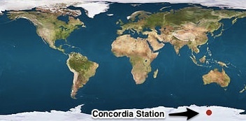
At the end of last year we received an email on our support center from an unusual location. It was sent by Giovanni Bianchini an italian physicist researching at Concordia Station, located in East Antarctica (see the red dot in the map below!) where the hottest temperature is around -25C?/-13F. He was working on a project based on Arduino and yes, this is the Arduino project based in the most southern location ever! When we realized that we thought of getting in touch with him and discover the details.

Giovanni was very happy to start a conversation with us, shared  some pictures and explained  why and how he is using Arduino in Antartica.

 Tell us a bit more about Concordia Station and what you are doing there…

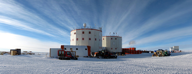
 Concordia Station is a scientific research base placed more or less in the middle of the plateau region, East Antarctica. This site is peculiar for the fact of being surrounded of at least 1000 km of ice plain in every direction, a condition that provides relatively stable and unperturbed weather conditions and a dry and very transparent atmosphere, that is the reason for which it has been chosen for astronomic and atmospheric observations.

The downside is isolation: the nearest emplacement is the russian Vostok base, at a mere 700 km, while the italian and french bases on the coast, that are the intermediate stops for the researcher coming to Concordia, are both at more than 1000 km. Usually coming to Concordia involves a 7-8 hours flight from Christchurch (NZ) to the italian “Mario Zucchelli” or the US “Mc Murdo” bases and a second 5 hours flight to Concordia. In alternative it’s possible to reach the french Dumont D’Urville base from Hobarth (AU) with a 7 days (more or less, much more than less…) cruise on the “L’Astrolabe” ship, and fly to Concordia. Since every stop in a base usually involves one or more days of stop, depending on the weather conditions, reaching Concordia is somewhat an adventure itself…

What is your job at the station?

Most of the instrumentation operating in Concordia is installed in some “shelters” placed some hundreds of meters upwind from the base, in order to sample unperturbed air. The shelters are put on elevated platforms to prevent snow accumulation, and are heated and connected to the base LAN, so the instrumentation can be remotely operated.

Specifically I work on atmospheric physics, and in the past two year I am responsible of a scientific project (Concordia Multi-Process Atmospheric Studies) that involve several instruments performing vertical remote sensing of atmospheric properties. The setup include two LIDARs, one SODAR, and an infrared spectroradiometer (Radiation Explorer in the Far-Infrared – REFIR).

All this instrumentation is installed in the Physics shelter, and operates continuously, even during the winter period, in which the base is completely isolated for almost 9 months and is crewed by only 12 persons. This implies that the instruments operating during winter should require the least attendance possible from the reduced crew, and possibly should be remotely accessed from Italy for checking and maintenance.

How are you using Arduino at the base?

While the shelters are quite a comfortable workplace for researchers and technicians, they present a critical (and maybe unexpected) problem for the instrumentation: overheating. The small volume, good thermal insulation, high density of powered devices, united with the low heat transfer capacity of the very dry air inside, makes heat dissipation a difficult task.

 For this reason, the first application I found for an Arduino board in Antarctica has been a cooling system for the REFIR spectroradiometer.

This optical instrument features tens of optical components with critical alignment requirements, so in the past years every time the instrument was subject to a strong thermal cycle, it needed to be realigned.

The original design provided just a simple heater with an analog proportional control loop (go figure you had to heat things at the south pole). Luckily, providing cooling power was as simple as getting air from outside and sending it to the instrument box through a tube. A valve and a fan regulate the cool air flow according to the instrument temperature.

The old heaters, the flow valve (servo controlled) and the cooling fan all are controlled by an Arduino Uno board, with a simple proportional loop that allows a thermal stability of a few tenths of degree.

Using an Ethernet Shield, all the system parameters (temperature, setpoint, cooling and heating gain, valve position) can be monitored through a simple web interface that gives this kind of output:

REFIR-PAD
thermal control
(commands: T, R, H, F, G, V, M, Z)
setpoint = 20.00
averages = 128
threshold = 0.10
fan_gain = 300
htr_gain = 200
valve_full = 0
valve_mid = 0
valve_zero = 38
temperature = 20.49
fan_drv = 118
htr_drv = 0
val_pos = 0

Parameters can also be set sending commands to the web server on the arduino board, for example, the command:

http://192.168.14.3:81/&T210

changes the setpoint temperature to 21.0 C

How does it work?

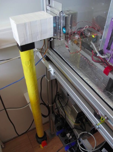
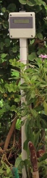
(see picture above) The yellow pipe  goes through the floor to get cool air from the outside, with a manual emergency valve and the servocontrolled flow control valve (the black block below the white box).

The white box connects the pipe to a standard 8cm computer fan that blows the air inside the instrument enclosure. the control system is also inside the instrument box, the green led indicates cooling in progress.

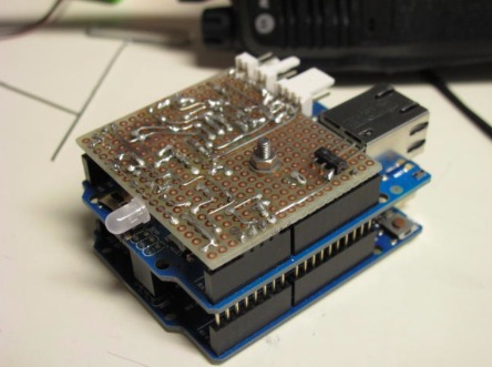
The custom shield (see pic above) is used to interface the Arduino with the various system components. The big transistor (2N3904) drives the cooling fan, the two smaller ones (2N2222) control the green/red led that signals cooling or heating. The voltage regulator provides the ~8v needed by the arduino board (could work without, but at 12v it overheats a lot…)

The heater is made by three transistors in series mounted on heat sinks with a small fan each, and is driven directly by a digital output pin on the arduino, the servo on the flow valve is also driven directly by a pwm output.

Download the Arduino Sketch here.
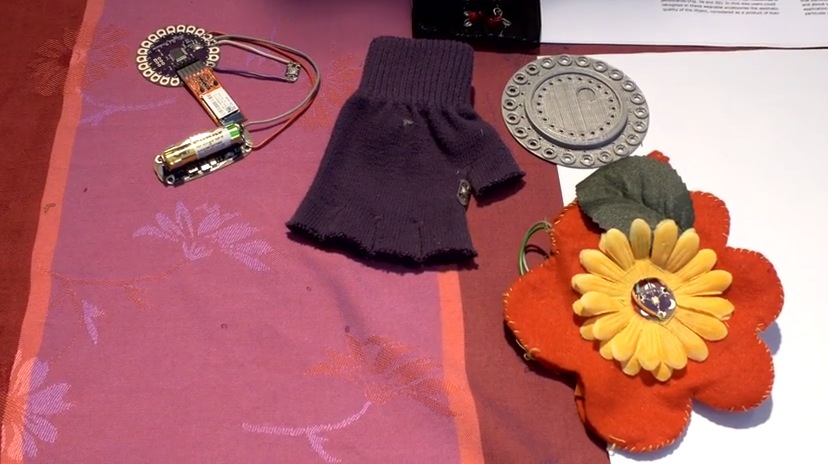
 

Arduino Blog 12 Jan 17:25

Simple and Inexpensive Heartbeat Detector

There are many ways to detect a heartbeat electronically. One of the simpler ways is to take [Orlando’s] approach. He’s built a finger-mounted pulse detector using a few simple components and an Arduino.

This circuit uses a method known as photoplethysmography. As blood is pumped through your body, the volume of blood in your extremities increases and decreases with each heartbeat. This method uses a light source and a detector to determine changes in the amount of blood in your extremities. In this case, [Orlando] is using the finger.

[Orlando] built a finger cuff containing an infrared LED and a photodiode. These components reside on opposite sides of the finger. The IR LED shines light through the finger while the photodiode detects it on the other side. The photodiode detects changes in the amount of light as blood pumps in and out of the finger.

The sensor is hooked up to an op amp circuit in order to convert the varying current into a varying voltage. The signal is then filtered and amplified. An Arduino detects the voltage changes and transmits the information to a computer via serial. [Orlando] has written both a LabVIEW program as well as a Processing program to plot the data as a waveform. If you’d rather ditch the PC altogether, you might want to check out this standalone heartbeat sensor instead.


Filed under: Arduino Hacks

IKEA Hack Music Visualizer Table

An ordinary IKEA table becomes the center of attention when it's turned into a music visualizer!

Read more on MAKE

MAKE » Arduino 11 Jan 18:01

Temperature Data Logger Logs Temperature Over Time

[Husham] not only likes his electronics projects but clearly enjoys documenting them as well. He’s written a nice Instructable on a Temperature Data Logger that he has built and thankfully makes his code available for others to use. The end product is cleanly designed and made for weather-proof outdoor applications.

As you may expect, the brains behind this operation is an Arduino. It is coupled with a Real Time Clock to maintain accurate timing as well as an SD Card Module which is used to store the data collected. In this case, the temperature is read by a LM35 temperature sensor and that value, along with the time, is recorded to a .csv file on the SD card in one minute intervals.

There is also an LCD screen that displays the date, time and current temperature. To save battery life the LCD backlight is normally off. It can be turned on using a magnet that interacts with a hall effect sensor on the top of the case. This worked so well that [Husham] installed a second hall effect sensor on the side of the case that resets the Arduino. Speaking of the case, it is a weather proof PVC electrical box with a conduit adapter installed on the bottom side. A battery pack made up of two used laptop cells housed in a piece of conduit supplies 7.2 volts to the Arduino and other components. Unfortunately, there’s no word on how long the battery pack lasts. Once the data is logged, the SD card can be removed and the .csv file opened in spreadsheet software to make a graph showing temperature change over time.


Filed under: Arduino Hacks, green hacks