Understanding Custom Signal Protocols with Old Nintendos
For retro gaming, there’s really no substitute for original hardware. As it ages, though, a lot of us need to find something passable since antique hardware won’t last forever. If a console isn’t working properly an emulator can get us some of the way there, but using an original controller is still preferred even when using emulators. To that end, [All Parts Combined] shows us how to build custom interfaces between original Nintendo controllers and a PC.
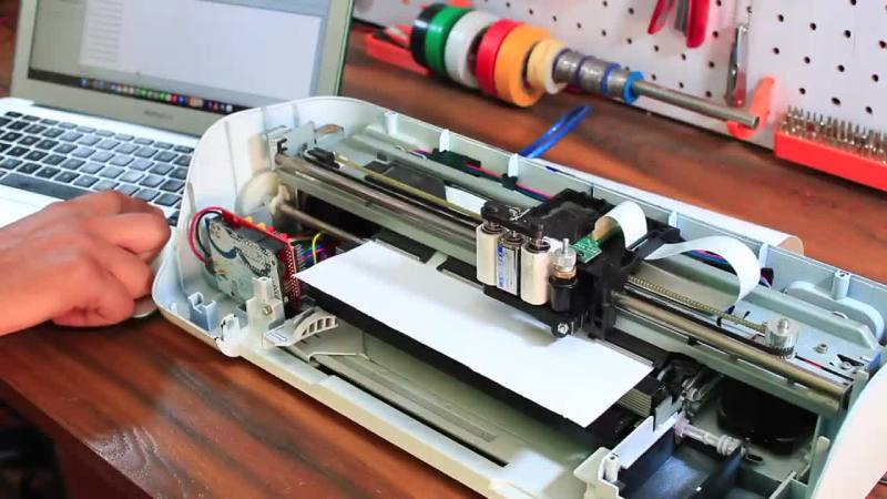
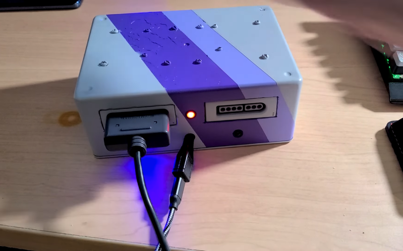
The build starts by mapping out the controller behavior. Buttons on a SNES controller don’t correspond directly to pins, rather a clock latches all of the button presses at a particular moment all at once during each timing event and sends that information to the console. To implement this protocol an Adafruit Trinket is used, and a thorough explanation of the code is given in the video linked below. From there it was a simple matter of building the device itself, for which [All Parts Combined] scavenged controller ports from broken Super Nintendos and housed everything into a tidy box where it can be attached via USB to his PC.
While it might seem like a lot of work to get a custom Nintendo controller interface running just because he had lost his Mega Man cartridge, this build goes a long way to understanding a custom controller protocol. Plus, there’s a lot more utility here than just playing Mega Man; a method like this could easily be used to interface other controllers as well. We’ve even seen the reverse process where USB devices were made to work on a Nintendo 64.