Pinewood Derby Scale Measures CG
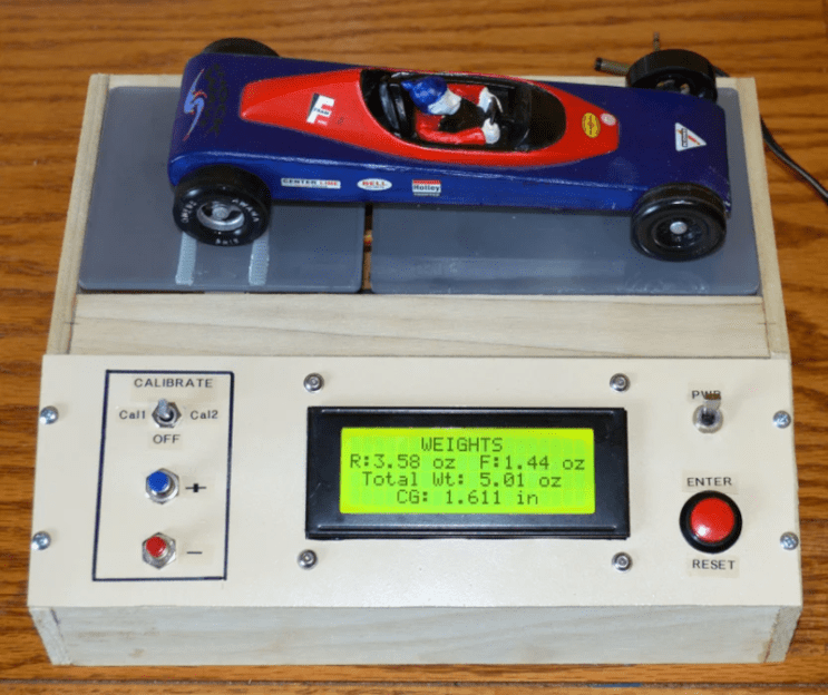
If you suffer from nostalgia, you might remember carving a block of wood into a car, adding some wheels, and racing it against other contestants in a pinewood derby. Today’s derby is decidedly high tech though, and we were impressed with this car scale that also figures out the car’s center of gravity.
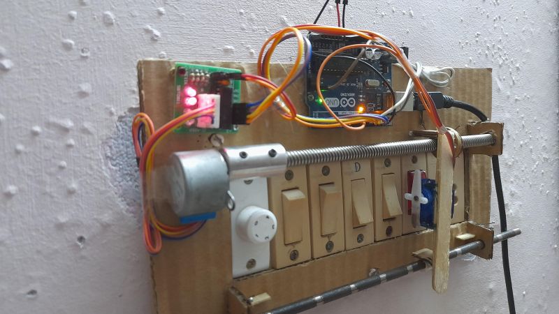
Based on an Arduino, of course, along with a pair of HX711 load cells. Why a pair? That’s how the device measures the center of gravity is by weighing the front and rear of the car separately.
We really liked the wooden case and found the use of wood satisfying if not ironic. Our only input is that since you need the wheelbase of the car to do the CG calculations, we’d have glued a ruler down. On the other hand, probably any self-respecting pinewood derby creator knows their wheelbase by heart.
Why does CG matter? If you are too far forward, you lose some acceleration. If you are too far back, the front wheels might pop up. With this device, you can know exactly where your center is and make adjustments accordingly.
If you’d rather build something for the actual race, why not a photo finish system? Or, perhaps you need a jet-powered (illegal) entry.