This funny robot pets your dog’s head and feeds them a treat
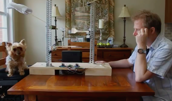
While this recent project may look like something straight out of Simone Giertz’s notebook, it’s actually the brainchild of James Cochrane. The engineer, who admittedly loves building all sorts of crazy machines, has developed an apparatus he calls the IoT Robot People/Pet Affectionator.
As its name would suggest, the Affectionator is an Arduino Nano-driven device that automatically gives his dog T-Bone a pat on the head along with a spoon-fed treat at the touch of an arcade button. That’s not all, though. It even allows the pup to reciprocate by pressing his own button and sending over a token of his appreciation on a fork–which in Cochrane’s case is a gummy worm.
Aside from the Arduino, the Affectionator is equipped with two H-Bridge motor drivers, two geared Pittman motors, and two geared hobby motors.
These days people are more connected with each other, however we are experiencing fewer physical interactions. This device will allow you to provide affection either locally or remotely to your pet without any physical contact. If your pet decides you are also worthy of their affection they can also reciprocate with a pat on the head and a tasty treat.
One day while giving my dog T-Bone a scratch behind the ears I came up with this silly idea. A robot which gives you a pet on the head and feeds you a treat. With the IoT, you can also build two of these and network them across the Internet.
Intrigued? Watch the hilarious idea in action below!