Staring at the Sun: Erasing an EPROM
Flash memory is the king today. Our microcontrollers have it embedded on the die. Phones, tablets, and computers run from flash. If you need re-writable long term storage, flash is the way to go. It hasn’t always been this way though. Only a few years ago EPROM was the only show in town. EPROM typically is burned out-of-circuit in a programming fixture. When the time comes to erase the EPROM, just pop it under an ultraviolet (UV) bulb for 30 minutes, and you’re ready to go again. The EPROM’s quartz window allows UV light to strike the silicon die, erasing the memory.
The problem arises when you want to use an EPROM for long term storage. EPROM erasers weren’t the only way to blank a chip. The sun will do it in a matter of weeks. Even flourescent light will do it — though it could take years.
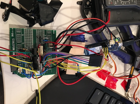
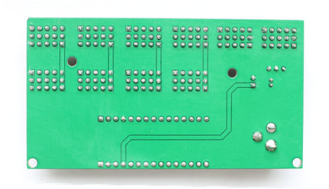
 [TechEkspert] wanted to learn about the nature of erasing an EPROM with the sun, so he got out an old EPROM and started hacking. (translated link) [TechEkspert] programmed the EPROM with a known pattern of ones and zeros. A pair of 74HC4040 counters would address the entire 32 KB memory of the EPROM. An Arduino Mini read the data out, storing it in an SD card. A bit of python code translated the data to PNG files, which were then combined to render a video.
The whole setup was placed on the roof in full sun. Then the waiting began. Nothing much happened for two weeks. Then some bits started to flicker. This means that sometimes they would read as a 0, and other times a 1. The sun was starting to destroy the stored data. Right at the 3 week mark, all the remaining data quickly started to disappear. In the end the entire chip was erased.
While [TechEkspert’s] chip could be re-programmed, that’s not always the case with EEPROM and flash. Check out this EEPROM killer which calculated how many cycles it took to destroy the electronically erasable storage in an Atmel ATmega328.
Filed under: classic hacks