Arduino, the world’s leading open-source ecosystem for Educators, Makers and IoT developers of all ages, today announced that Arduino LLC (aka Arduino.cc) and Arduino srl (aka Arduino.org) have settled their differences and signed a Settlement agreement.
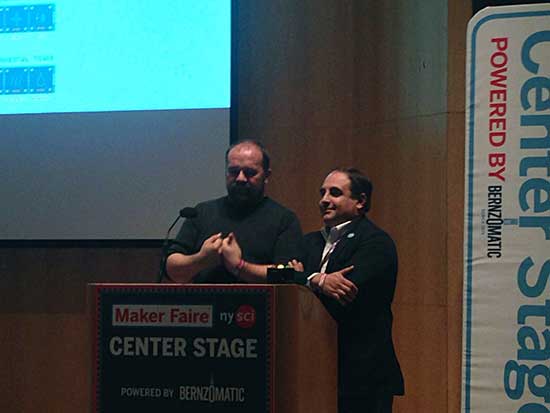
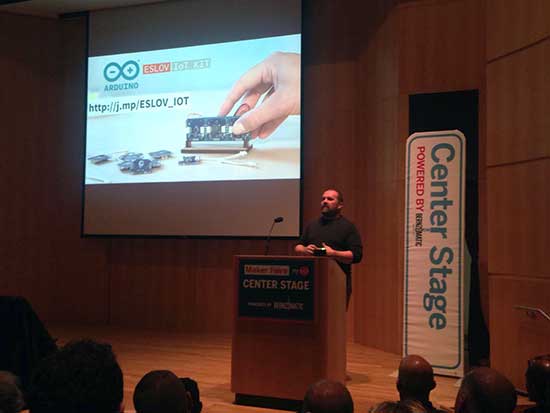
Massimo Banzi and Federico Musto took the stage today at the New York Maker Faire to announce the good news.
At the end of 2016, the newly created “Arduino Holding” will become the single point of contact for the wholesale distribution of all current and future products, and will continue to bring tremendous innovations to the market.
In addition, Arduino will form a not-for-profit “Arduino Foundation” responsible for maintaining the open source Arduino desktop IDE, and continuing to foster the open source movement by providing support for a variety of scholarships, community and developer initiatives.
Massimo Banzi, Co-Founder of Arduino LLC, commented, “Today is one of the best days in Arduino history. This allows us to start a new course for Arduino made of constructive dialogue and disruptive innovation in the Education, Makers and IoT fields. The Arduino Foundation will allow us to champion the core values of the Arduino Community within the open source ecosystem and to make our commitment to open source stronger than ever. This is really a new beginning for Arduino!”
“Of course, we are thrilled to resolve the issues that have taken place over the past couple of years, and the team is working together to continue to offer the best open hardware and software,” said Federico Musto, CEO & President of Arduino Srl. “We know how passionate our partners and developers are about Arduino, and the growth and loyalty has been astonishing. Arduino developers will continue to see amazing technical developments including NFC, BLE, voice controls, and more, to fuel the IoT growth and other innovations.”
There are a lot of unusual listings on eBay. If you’re wondering why someone would have a need for shredded cash, or a switchblade comb, or some “unicorn meat” (whatever that is), we’re honestly wondering the same thing. Sometimes, though, a listing that most people would consider bizarre finds its way to the workbench of someone with a little imagination. That was the case when [tinkartank] found three pipe organ pipes on eBay, bought them, and then built his own drivers.
The pipes have pitches of C, D, and F# (which make, as far we can tell, a C add9 flat5 no3 chord). [tinkartank] started by firing up the CNC machine and creating an enclosure to mount the pipes to. He added a church-like embellishment to the front window, and then started working on the controls for the pipes. Each pipe has its own fan, each salvaged from a hot air gun. The three are controlled with an Arduino. [tinkartank] notes that the fan noise is audible over the pipes, but there does seem to be an adequate amount of air going to each pipe.
This project is a good start towards a fully functional organ, provided [tinkartank] gets lucky enough to find the rest of the pipes from the organ. He’s already dreaming about building a full-sized organ of sorts, but in the meantime it might be interesting to use his existing pipes to build something from Myst.
Well all know cellular automata from Conway’s Game of Life which simulates cellular evolution using rules based on the state of all eight adjacent cells. [Gavin] has been having fun playing with elementary cellular automata in his spare time. Unlike Conway’s Game, elementary automata uses just the left and right neighbors of a cell to determine the next cell ahead in the row. Despite this comparative simplicity, some really complex patterns emerge, including a Turing-complete one.
[Gavin] started off doing the calculations by hand for fun. He made some nice worksheets for this. As we can easily imagine, doing the calculations by hand got boring fast. It wasn’t long before his thoughts turned to automating his cellular automata. So, he put together an automatic cellular automator. (We admit, we are having a bit of fun with this.)
This could have been a quick software project but half the fun is seeing the simulations on a purpose-built ecosystem. The files to build the device are hosted on Thingiverse. Like other cellular automata projects, it uses LED matrices to display the data. An Arduino acts as the brain and some really cool retro switches from the world’s most ridiculously organized electronics collection finish the look of the project.
To use, enter the starting condition with the switches at the bottom. The code on the Arduino then computes and displays the pattern on the matrix. Pretty cool and way faster than doing it by hand.
Adjust the phase current, crank up the microstepping, and forget about it — that’s what most people want out of a stepper motor driver IC. Although they power most of our CNC machines and 3D printers, as monolithic solutions to “make it spin”, we don’t often pay much attention to them.
In this article, I’ll be looking at the Trinamic TMC2130 stepper motor driver, one that comes with more bells and whistles than you might ever need. On the one hand, this driver can be configured through its SPI interface to suit virtually any application that employs a stepper motor. On the other hand, you can also write directly to the coil current registers and expand the scope of applicability far beyond motors.
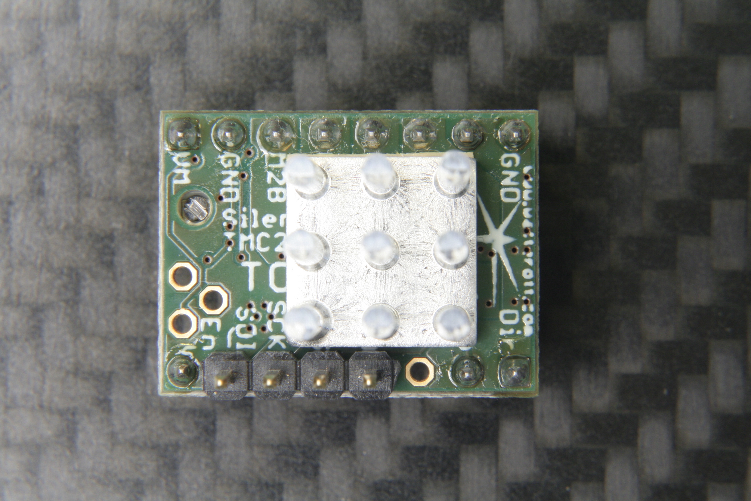
The TMC2130 SilentStepStick’s top side with SPI headers and heatsink.
Last month, we took a closer look at microstepping on common stepper driver ICs, but left out the ones that we actually want to use: the smart ones. Trinamic provides some of the smartest stepper motor drivers on the market, and since the German hacker store Watterott released their SilentStepStick breakout boards for the TMC2100 and TMC2130, they are also setting a new standard for DIY 3D printers, mills and pick-and-place robots. I recently acquired a set of both of them for my Prusa i3 3D printer, and the TMC2130 with its SPI configuration interface really caught my attention.
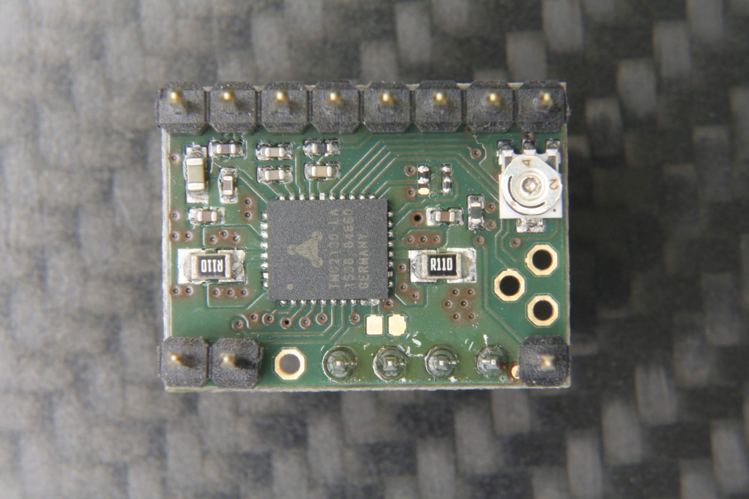
The TMC2130 SilentStepStick should not be confused with the — far more popular — TMC2100 variant. As the name suggests, it comes as a StepStick-compatible breakout board, and just like it’s famous sibling, features a Trinamic IC on the bottom side of the little PCB. Several vias and copper spills conduct heat away from the IC’s center pad, allowing a heatsink on the top side to effectively cool the driver.
The bottom side with the stand-alone mode solder blob jumper next to the IC.
However, unlike the TMC2100, this one won’t let your motors spin right away. You’ve got two options: Hard-wire it in stand-alone mode, which practically turns it into a TMC2100, or hook up to its SPI-interface and dial in if you want your stepper motor shaken or stirred. In fact, plentiful configuration registers make the TMC2130 an extremely hackable chip, so I’m not even thinking about bridging that solder jumper on the SilentStepStick’s bottom side that activates the stand-alone mode.
First Steps
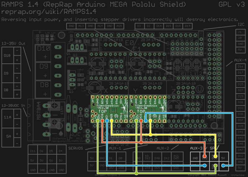
Wiring the TMC2130 to a classic RAMPS 1.4.
As said, before the driver does anything, it wants to be configured, and it’s worth mentioning that all configuration registers are naturally volatile, so if I want to use them in my 3D printer, I need to configure them as part of the printers startup routine.
The RAMPS 1.4 on my 3D printer breaks out the hardware SPI interface of the underlying Arduino through its AUX3 pin header, along with two additional digital pins (D53 and D49), which I used for the cable select signals. After crimping a cable to connect two TMC2130’s to the AUX3 header, I could start digging into the software part.
Watterott provides an example sketch, which writes a basic configuration to the driver’s registers and spins an attached stepper motor. Great stuff, but the datasheet describes 23 configuration registers waiting to be finely tuned, and 8 more to read diagnosis and status data from. So, I wrote a little Arduino library that would make the numerous configuration parameters available in a more practical way. From there, I could just include my library into the Marlin-RC7 3D printer firmware I’m using. Luckily, the current Marlin release candidate already features support for TMC26X drivers, so I could reuse some of its code to put together a Marlin fork that includes 59 of the TMC2130’s parameters in its define-based configuration files. And then, I could take the little buddies out for a spin.
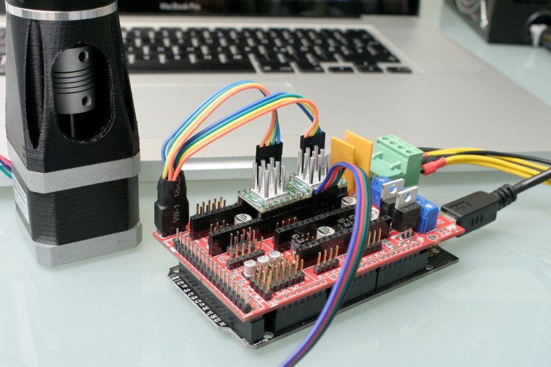
First steps on a RAMPS 1.4 on a somewhat-uino (sorry Massimo). The testing-contraption to the left is a NEMA 17 stepper motor attached to an encoder.
Taking Them For A Spin
With the hardware set up and the software working as supposed, I ran a few sanity tests: toggling parameters on and off and checking how the driver’s behavior changes during printing. Since the TMC2130 let’s you tune almost everything it’s doing, that’s a good first step that helps to eliminate some variables and picking others that are worth a deeper look. Most of the settings can be changed on the fly and mid-print, however, not all parameters can actually be safely changed while the motors are running.
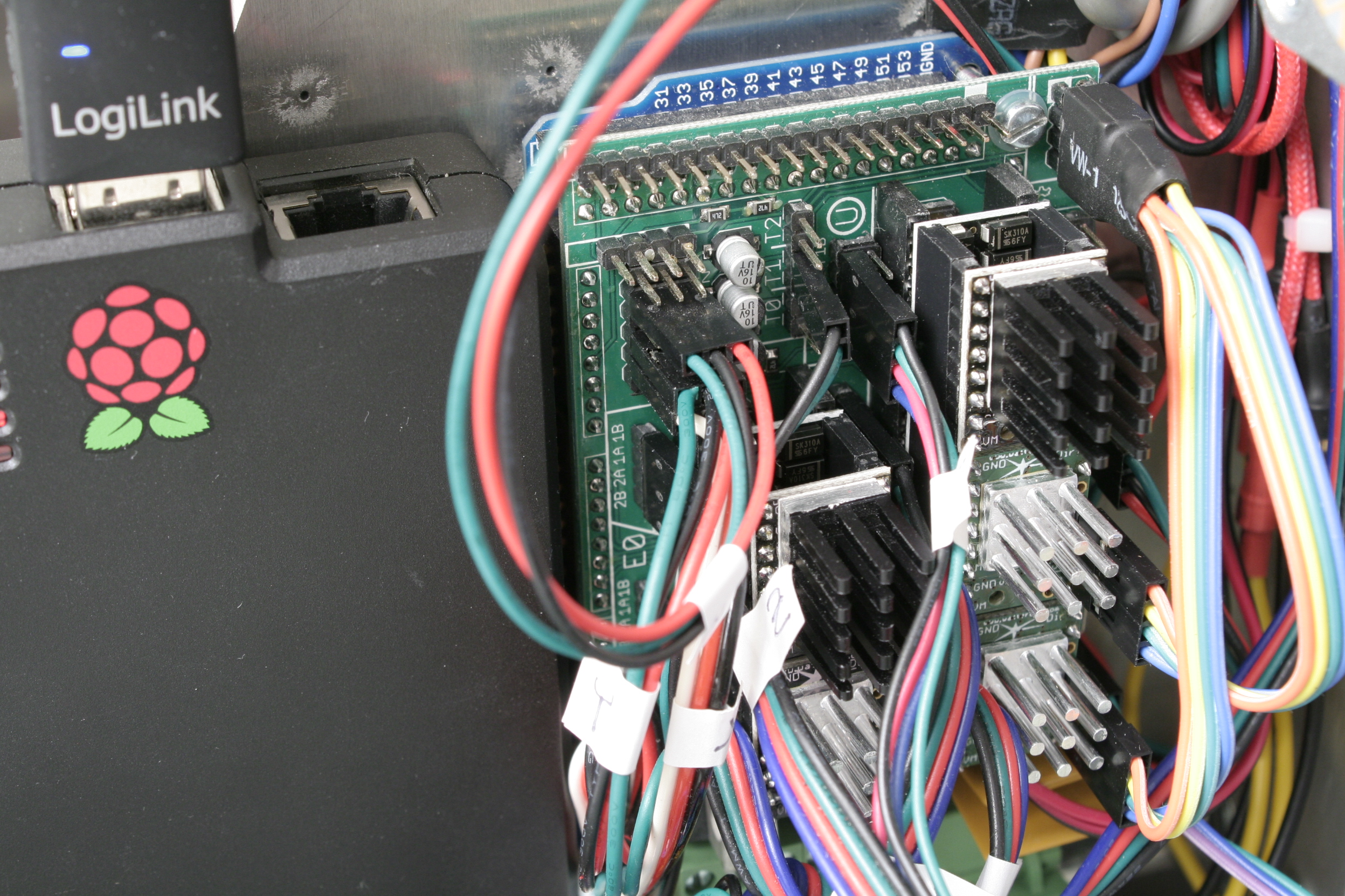
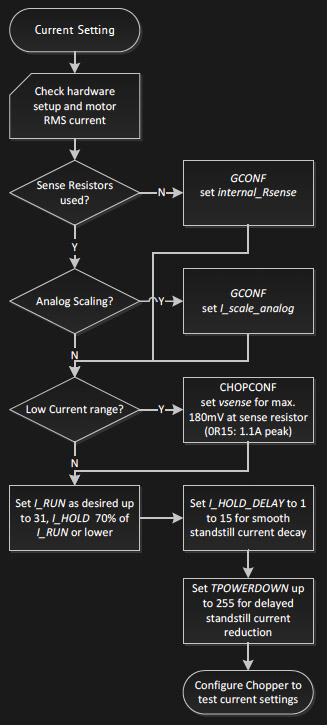
The TMC’s in service. I’m using the SPI-configurable TMC2130’s (silver heatsink) for the X- and Y- axis. The Z-axis and the extruder feature the TMC2100 (black heatsink). All of them are sitting on additional free-runner diode protection shields.An excerpt of Trinamic’s thorough quick start guide.
To actually tune the drivers for a certain application, Trinamic provides a quick start guide in the datasheet, as well as detailed information on each parameter, and on how they interact. Basically, the first step is adjusting the RMS coil current by using the onboard potentiometer on the SilentStepSticks. Then, we need to chose the analog input pin as a current scaling reference to actually make use of the potentiometer. The mentioned library lets me do this through a simple method:
myStepper.set_I_scale_analog(1); // 0: internal, 1: AIN
The running and holding current are the first real parameter that should be tuned, with the running current typically at the desired maximum current, and the holding current at 70% of this value. The delay between a stillstand and the transition from running current to holding current can be adjusted between 0 and 4 seconds, and for now, I set it to 4 seconds, practically disabling the current reduction while the 3D printer is running. The three values share one write-only register, so the corresponding method call looks like this:
and sets the running current to 100% (≙ 31), the holding current to about 70% of this value (≙ 22), and the delay between the two to 4 seconds (≙ 5).
I want torque, so I can leave stealthChop disabled. The datasheet suggests some starting values for configuring the chopper’s off time and the comparator’s blank time settings, but since it’s a key tradeoff between switching noise and torque, it makes sense to iterate through other values as well. The library methods for the two values look like this:
And finally, I need to pick a microstepping resolution and choose if I want to make use of the 256 microstep interpolation feature, covered later in this article:
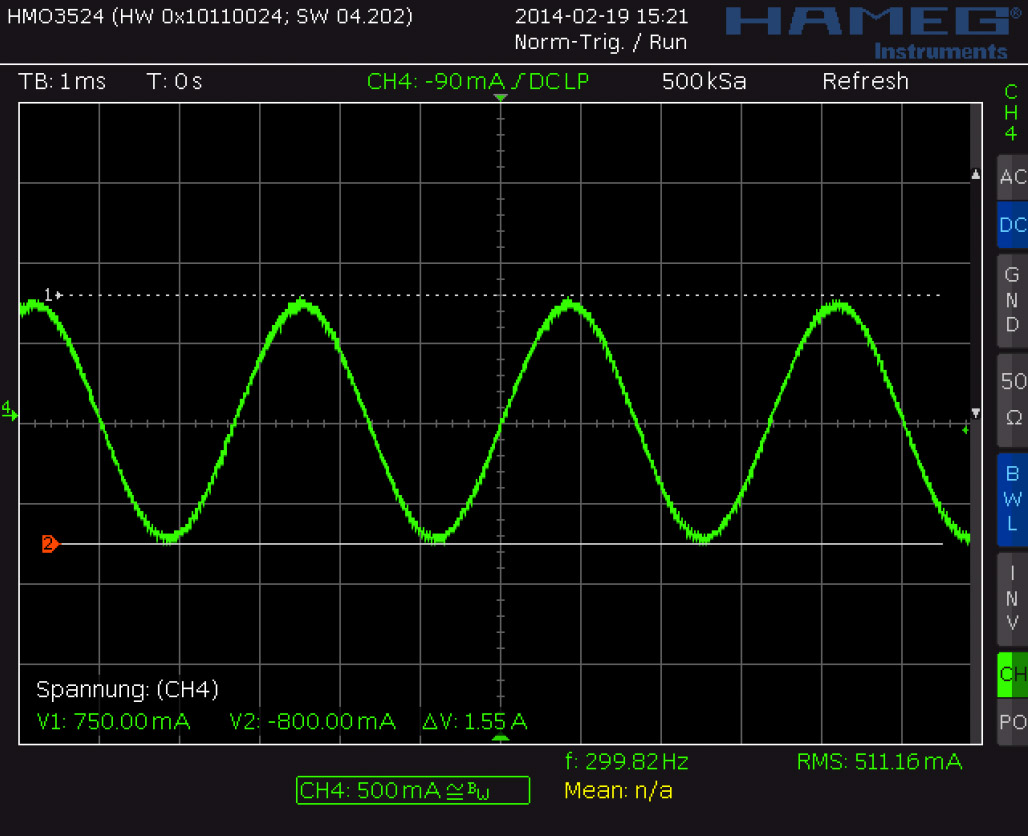
I have yet to walk through the entire tuning procedure, which includes monitoring the coil current on the scope and eliminating distortions in the zero crossing, but I’m getting a clue of the driver’s potential.
Juice
It’s maximum continuous RMS current of about 1.2 A per coil (at least in the QFN package on the SilentStepSticks) lets it look like a low-current driver, inferior to the common A4988 and DRV8825. In practice, it outperforms both of them by making intelligent use of a 2.5 A peak current margin. This gives it more than enough torque for 3D printing. I wouldn’t recommend pushing them over 0.9 A RMS though since the IC will momentarily pull more current if it needs more. For SilentStepStick users, that’s a Vref of 0.88 V. Through the SPI-interface, you can choose how much current you want to send through the motor coils when it’s spinning, and when it’s idling. You can choose after how many seconds it will start to decrease the current to a lower holding current when the motor is in standstill, and then to an even lower idling current. And, of course, you can also set it to squeeze out the maximum juice for everything.
Shifting The Gears
Where it starts getting interesting are settings like the high-velocity mode. Above a configurable velocity threshold, the driver offers you to automatically switch the chopper to a faster decay time to squeeze out some extra speed. You can also literally shift the gears by letting the driver internally switch from microstepping to full-step mode once it’s up to speed.
Microstepping
Choosing a finer microstepping resolution smoothens the stepper’s movement, reduces vibrations and sometimes even increases the positioning accuracy. However, it also multiplies the load on the microcontroller, which has to churn out 16, 32 or 256 times more step pulses per second. The TMC2130 lets you pick an input resolution between 1 and 256 microsteps per full-step, and then gives you the option of interpolating the output resolution to 256 microsteps. This allows for smooth operation even on increasingly retro 8-bit AVR motion controllers, which cannot deliver high step frequencies. Also, by configuring the TMC2130’s interface to double-edge step pulses, you can at least double the step frequency at almost no cost. Given that the modern IC still features the classic step/direction interface and even an enable pin, those few additional features actually make it a sweet drop-in upgrade for less-recent CNC and 3D printer electronics.
Noise Reduction
The TMC2130’s datasheet promises undistorted output with stealthChop.
Just like the TMC2100, the TMC2130 features two efficient and silent drive modes: spreadCycle, and stealthChop. The former delivers high torque at relatively low noise emissions, the latter one is almost inaudible but delivers a dramatically reduced torque. The flexible IC also allows you to tweak the chopper yourself to find the right balance between torque, noise, and efficiency for your application. One of the more noteworthy options in this regard is the possibility of randomizing the chopper’s off time. Since most of the audible noise is released due to dubstep the chopper busily switching the stepper motor’s coils, this option spreads the noise over a wider frequency range to subjectively silence the stepper motor.
Stall Detection
The TMC2130 notices when the motor is stalled and losing steps by measuring the motor’s back EMF. Along the way, it counts missed steps, allowing the controller to compensate for otherwise irreversible step-loss. It’s also a great way to react to obstacles rather than running into them full-force and, of course, the feature can be used as an axis endstop. Trinamic calls this feature StallGuard, and just like anything else in this motor driver, it’s highly configurable.
Direct Mode
Instead of letting the motor driver handle everything for you, you can also choose the direct mode. This mode practically turns the driver into a two-channel, bipolar constant-current source with SPI interface. You can still use it as a motor driver, but the possibilities reach far beyond that. It’s worth mentioning that the datasheet might be a bit confusing here, and the corresponding XDIRECT register actually accepts two signed 9 bit integers (not 8 bit) for each coil and operates as expected within a numeric range of, naturally, ± 254 (not ± 255) to vary the current between ± Imax/RMS..
The Takeaway
About half a year after the release of Watterott’s breakout board, the potential of smarter stepper motor drivers piqued the curiosity of the 3D printing community, but not much has happened in terms of implementation. Admittedly, it takes some effort to get them running. If you’re still busy dialing in the temperature on your 3D printer, you surely don’t want to add a few dozen new variables, but if you’re keen on getting the best out of it, the TMC2130 has a lot to offer: low-noise printing, high-speed printing, print interrupt on failure and recovery from lost steps. Because the driver IC is so hackable, it’s clearly intended to be tuned in to accommodate specific applications. Throwing it on a general purpose test bench probably won’t yield meaningful, general purpose results.
I hope you enjoyed taking a look at a smarter-than-usual stepper motor driver, as one of the new frontiers of DIY 3D printing, and as an interesting component with many other applications. If you’re thinking about experimenting with this IC or breakout board in your 3D printer, feel free to try my Marlin fork to get started. If you’re building something entirely different, the underlying Arduino library will help you out. Who else is using this part? I’ll be glad to hear about your ideas, applications, and experiences in the comments!
In this post we are going to discuss how to upload temperature on thingspeak channel using sim 900 and arduino uno. As I had already uploaded the data on thingspeak channel using sim 900 and terminal software.
Introduction:
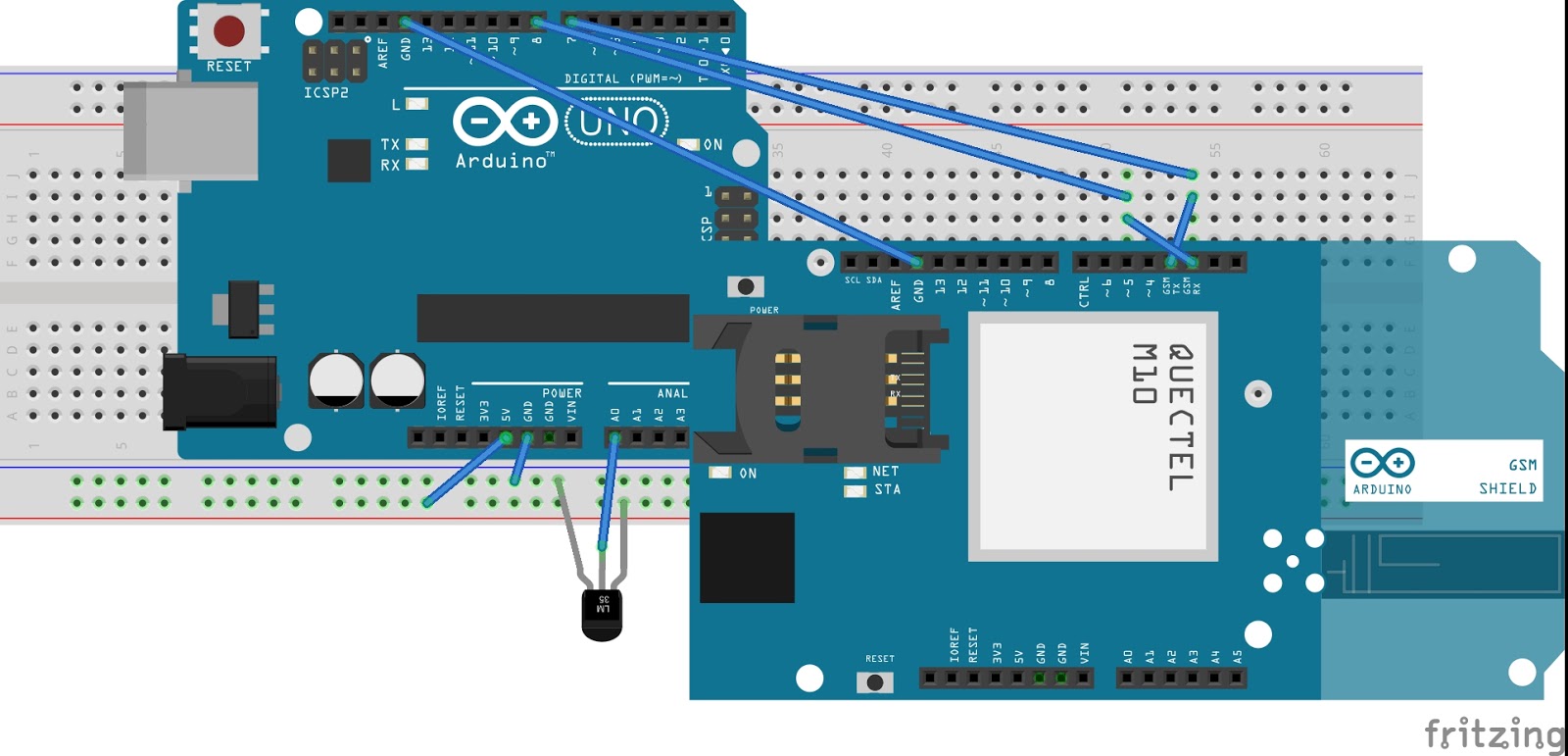
This project is a wireless temperature logger on thingspeak channel using gsm module and arduino. For temperature sensor, we are using lm35, that gives output in millivolt which can be easily calibrated in terms of °C. We have to use adc module, since it's an analog sensor. Once the raw data is converted into temperature, we can upload the data.
Now, we are ready to upload the data on thingspeak channel. Thingspeak provides api for uploading of data. Before this, we have to use activate GPRS on sim900. We also to provide APN for accessing the internet. After activating the GPRS, we have to use GET like this:
GET http://api.thingspeak.com/update?api_key=QZFXXXXXXXXXXX&field1=data
Replace this api with yours, and data is the data you want to be upload. You can upload a number of field like temperature, pressure, humidity, etc.
Even a cursory glance through a site such as this one will show you how many microcontroller boards there are on the market these days. It seems that every possible market segment has been covered, and then some, so why on earth would anyone want to bring another product into this crowded environment?
This is a question you might wish to ask of the team behind Explore M3, a new ARM Cortex M3 development board. It’s based around an LPC1768 ARM Cortex M3 with 64Mb of memory and 512k of Flash running at 100MHz, and with the usual huge array of GPIOs and built-in peripherals.
The board’s designers originally aimed for it to be able to be used either as a bare-metal ARM or with the Arduino and Mbed tools. In the event the response to their enquiries with Mbed led them to abandon that support. They point to their comprehensive set of tutorials as what sets their board apart from its competition, and in turn they deny trying to produce merely another Arduino or Mbed. Their chosen physical format is a compact dual-in-line board for easy breadboarding, not unlike the Arduino Micro or the Teensy.
If you read the logs for the project, you’ll find a couple of videos explaining the project and taking you through a tutorial. They are however a little long to embed in a Hackaday piece, so we’ll leave you to head on over if you are interested.
We’ve covered a lot of microcontroller dev boards here in our time. If you want to see how far we’ve come over the years, take a look at our round up, and its second part, from back in 2011.
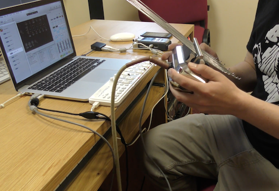
With an accelerometer and capacitive sensing, even a beginner can produce some great tunes with this DIY device.
If you like making beautiful music, but would rather not actually practice this skill, perhaps this thumb piano and controller by producer/DJ Rob Blazey would be a good instrument to pick up. His project, called “Kalimbo,” employs an Arduino to translate manipulations of metal rods, along with movement of the piano itself, into Open Sound Control (OSC) messages. These are then be used to produce music.
You first hear its awesomeness around the 1:00 mark in the video seen below. Even just moving it around sounds good, but it becomes incredible when he really starts playing just before 2:00!
Inside the instrument there is an Arduino with an accelerometer and a capacitive sensing wire, which is connected to the insulated bridge at the back, so touching the edge of that bridge acts as a trigger or switch or can control things more precisely depending on how hard you press it.
Intrigued? You can find more background on this project in mrblazey’s video description.
With Alain Mauer’s Arduino glasses and a Bluetooth multimeter, electrical data is always in view!
If you’re in a job where you have to take readings inside a live electrical panel, one thing that’s inconvenient, and even dangerous at times, is having to look away from your hands to read your multimeter. With hopes of “making an engineer’s life easier and safer,” Mauer solved this problem using an Arduino Pro Micro and a BLE module to show data from a Bluetooth-enabled multimeter. Now he can see data on a display that looks similar to a Google Glass device. Perhaps this method could be expanded to other devices in the future!
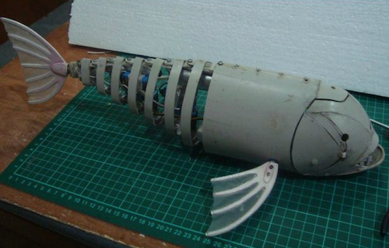
This robotic fish is made from bent PVC pipe and moves its tail for locomotion.
If you’re going to build an underwater vehicle, propeller control is the conventional solution. Eric Dirgahayu, however, created his underwater creature in the form of a fish, complete with a tail that powers it through the water, and pectoral fins that could, in theory, steer it in the correct direction. There is also a ballast tank to adjust its buoyancy. Interestingly, control of this “fish” is accomplished via a TV remote, so the surrounding water would need to be relatively clear.
Now we already have a complete fish robot body, we need to provide it with life! We will use the Arduino Pro Mini because the shape is small and can fit into safety box. In addition, you also need Pro Mini Arduino Motor Driver for control of ballast tanks, UBEX for power protection and two cell LiPo battery 1000mAh for power.


 Arduino.cc and Arduino.org have signed a settlement agreement that reconnects the two divisions into one group.


