Newsflash: A Bunch of Arduinos is Not an Autonomous Car
Nobody’s perfect. Sometimes you’re up late at night writing a blog post and you stumble upon an incredible story. You write it up, and it ends up being, well, incredible. IEEE Spectrum took the bait on this video (embedded below) where [Keran McKenzie] claims to have built a self-driving car for under $1,000 AUS with Arduinos.
The video is actually pretty funny, and we don’t think it’s intended to be a mass-media hoax as much as a YouTube joke. After letting the car “take over” for a few seconds, it swerves and [Keran] pretends to have hit something. (He’s using his knees people!) There are lots of takes with him under the car, and pointing at a single wire that supposedly makes the whole thing work. Yeah, right.
 We were a bit bummed, though. We don’t think you can even reliably interface a sensor system with the steering wheel, accelerator, and brakes for as little as one grand, but we would have been entirely happy to see it done. We’re not saying that the software to run an autonomous car is the easy part, but we’d love to have a hack at it if the hardware were affordable.
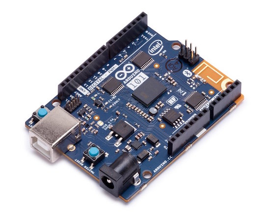
Anyway, if you’re looking for a real autonomous driving experience, we recommend starting by hacking RC cars and giving them substantially bigger brains than an Arduino. Once you’ve got that working, making progress to a real car is doable, but expensive. And it helps to be [geohot].
And lest you think we’re all holier-than-thou, check out our most embarrassing post ever. We could just curl up and die. Feel better soon, IEEE Spectrum!
Thanks [jpiat] for the tip!
Filed under: Arduino Hacks


 The first thing the team had to do was to mount the scissors so they would cut reliably. One of the stepper motors was attached to a drive wheel that had a bolt mounted on it. This went through one of the scissors’ handles, the other handle was held in place on the machine using screws. The second stepper motor was used to rotate the wheels that drives the cable through to the correct length. [2PrintBeta] used a