For those living in a high-rise, have you ever wondered what was going on behind the closed blinds of your neighbor’s home directly across from you?
Caretaker is a concept project that explores just that. It consists of a custom-made switch board with which you can control the lights of the flats opposite of yours, providing active entertainment that stimulates your senses better than passive media consumption.
If you want one of your own, simply take a picture of the building that you see from your window and Caretaker will design a laser-cut scale model of it for your use. The prototype runs on an Arduino and is battery-powered, allowing you to freely move it around.
The project is the work of Moholy-Nagy University of Art and Design Budapest (MOME) student, Máté Varga, in collaboration with Barbara Sterk, Miklos Erhardt, Adam Polhodzik, and FabLab Budapest.
With All Hallow’s Eve looming close, makers have the potential to create some amazing costumes we’ll remember for the rest of the year. If you’re a fan of the hugely addict-*cough* popular game Minecraft, perhaps you’ve considered cosplaying as your favorite character skin, but lacked the appropriate props. [Graham Kitteridge] and his friends have decided to pay homage to the game by making their own light-up Minecraft swords.
These swords use 3D-printed and laser-cut parts, designed so as to hide the electronics for the lights and range finder in the hilt. Range finder? Oh, yes, the sword uses an Arduino Uno-based board to support NewPixels LEDs and a 433Mhz radio transmitter and receiver for ranged detection of other nearby swords that — when they are detected — will trigger the sword to glow. Kind of like the sword Sting, but for friendlies.
All of the files for the parts are available on the project’s Thingverse page and the board setup can be purchased here. If you want to have some fun controlling the real world from inside Minecraft, check out how this fan uses it to turn on lamps in their home.
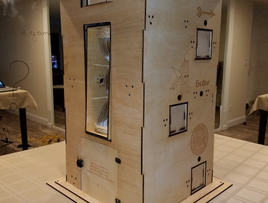
Inspired by The Goonies movie and The Room game, Guido Bonelli has constructed a piece of Arduino-controlled interactive furniture to entertain his guests.
After what appears to be a massive amount of work involving 3D printing, laser cutting, wiring, and programming, Bonelli has come up with a puzzle box that shouldn’t need any explanation. Using button presses and other interactions with it, participants are able to unlock a treasure box in the bottom, a working wooden safe!
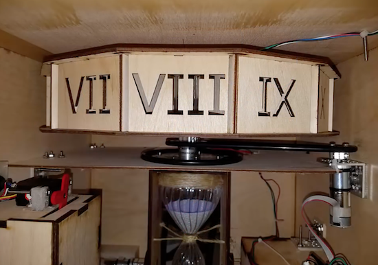
Additionally, the box tells time in a very unique way. It has an hourglass that is automatically flipped to indicate minutes, and Roman numerals at the top to reveal hours. You can see how it works and how it was assembled in the videos below!
I wanted to create a unique piece of furniture for my home which my guests could interact with. This time however, I wanted it to be something which I wouldn’t have to explain how it worked. Instead, I wanted mysterious scriptures scribed all over the sculpture to intrigue my guests.
At the heart of GoonieBox is of course an Arduino… Effortlessly whisking away my artistically written 0’s and 1’s into a symphony of movement, sound and game play. Taking approximately 800 hours of build time, GoonieBox is my greatest accomplishment by far in the world of Arduino.
Inspired by The Goonies movie and The Room game, Guido Bonelli has constructed a piece of Arduino-controlled interactive furniture to entertain his guests.
After what appears to be a massive amount of work involving 3D printing, laser cutting, wiring, and programming, Bonelli has come up with a puzzle box that shouldn’t need any explanation. Using button presses and other interactions with it, participants are able to unlock a treasure box in the bottom, a working wooden safe!
Additionally, the box tells time in a very unique way. It has an hourglass that is automatically flipped to indicate minutes, and Roman numerals at the top to reveal hours. You can see how it works and how it was assembled in the videos below!
I wanted to create a unique piece of furniture for my home which my guests could interact with. This time however, I wanted it to be something which I wouldn’t have to explain how it worked. Instead, I wanted mysterious scriptures scribed all over the sculpture to intrigue my guests.
At the heart of GoonieBox is of course an Arduino… Effortlessly whisking away my artistically written 0’s and 1’s into a symphony of movement, sound and game play. Taking approximately 800 hours of build time, GoonieBox is my greatest accomplishment by far in the world of Arduino.
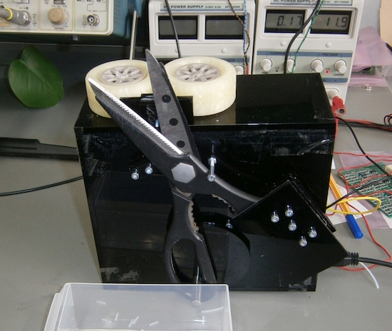
2PrintBeta solves the problem of cutting multiple cables with an innovative scissors setup.
At times, the 3D printing and engineering company 2PrintBeta needs to cut wires and other assorted materials to length. Sure, they could simply cut them by hand, but that takes time and their business is growing. An industrial cable cutter is quite expensive, so being an engineering company, they decided to make their own using a rather rugged pair of scissors actuated by a bolt attached to a drive disk.
For this operation, wire feeding is done by a pair of 3D-printed wheels, and the “brains of the operation” is provided by an Arduino Mega using stepper motor drivers.
The ideas ranged from razorblades to a holder for a dremel with a cut sheet. But a short test showed: scissors are sufficient. So why not use scissors?
The “Navigation Thing“ was designed and built by [Jan Mrázek] as part of a night game activity for high school students during week-long seminar. A night-time path through a forest had stations with simple tasks, and the Navigation Thing used GPS, digital compass, a beeper, and a ring of RGB LEDs to provide a bit of “Wow factor” while guiding a group of students from one station to the next. The devices had a clear design direction:
“I wanted to build a device which a participant would find, insert batteries, and follow the beeping to find the next stop. Imagine the strong feeling of straying in the middle of the night in an unknown terrain far away from civilization trusting only a beeping thing you found. That was the feeling I wanted to achieve.”
The Navigation Things (there are six in total) guide users to fixed waypoints with GPS, a digital compass, and a ring of WS2812 LEDs — but the primary means of feedback to the user is a beeping that gets faster as you approach the destination. [Jan] had only four days to make all six units, which was doable. But as most of us know, delivering on a tight deadline is often less about doing the work you know about, and more about effectively handling the unexpected obstacles that inevitably pop up in the process.
The first real problem to solve was the beeping itself. “Beep faster as you get closer to the destination” seems like a simple task, but due to the way humans perceive things it’s more complex than it sounds. We perceive large changes easier than small incremental ones, so a straight linear change in beep frequency based on distance doesn’t work very well. Similar problems (and their solutions) exist whether you’re controlling volume, brightness, or just about anything else that humans perceive. Instead of encoding distance as a beep frequency, it’s much more effective to simply use beeps to signal overall changes: beep noticeably slower as you move away, but beep much faster as you get close.
A “piezo” buzzer that was assumed to have no significant magnetic field, but in fact contained a magnet.
The other interesting problems were less straightforward and were related to the digital compass, or magnetometer. The first problem was that the piezo buzzers [Jan] sourced contained no actual piezo elements. They contained magnets – which interfered with the operation of the digital compass. After solving that, still more compass problems arose. When testing the final units in the field, the compass readings were not as expected and [Jan] had no idea why.
After careful troubleshooting, the culprit was found: the AA cells on the other side of the circuit board. Every AA cell has a faint (and slightly different) magnetic field, and the proximity and placement of the cells with respect to the magnetometer was causing the deviation. Happily, the fix was simple once the problem was understood: calibrate the compass every time new batteries are inserted.
If you’re interested in the Navigation Thing, check out the github repository. And on the topic of actual piezoelectric devices, piezos are implemented in a variety of clever ways. There are even piezo transformers and piezo vacuum pumps.
For less than $1,000, Keran McKenzie programmed his car to drive itself… or did he? That is the question, which has led to much debate online over the last couple of hours. (Although Hackaday has revealed the truth, it was one heck of an ad for Arduinos!)
Hoax aside, as hackers begin to see autonomous vehicles in various phases of testing, the question of “why can’t I do that?” is bound to come up. McKenzie seemingly attempted to do just that with an array of five cameras embedded in his 2012 Ford Focus where ultrasonic sensors were formerly mounted. While details of the project are slim (and now we know why), he does mention ‘using’ an Arduino for each camera, interfaced with a master board to put everything together. He also went on to ‘add’ a SparkFun MicroView inside the car for visual feedback of the supposed control system.
Impressive hacking/editing, however, as you see just after 3:00 in the video, trusting your life to a homemade vision system is probably not the greatest idea and is a build best left to professionals.
The Ford Focus that I have has an interesting feature, it has this home button on here. Now the home button doesn’t particularly do much other than tell the navigation system to turn on and show you the route home… It got me thining though, why can’t I push that button and have it take me home?