A beautifully-designed LEGO pneumatic compressor
LEGO sets have long been able to work with simple pneumatic controls, but what about a full air compressor built out of these components? Would this be possible?
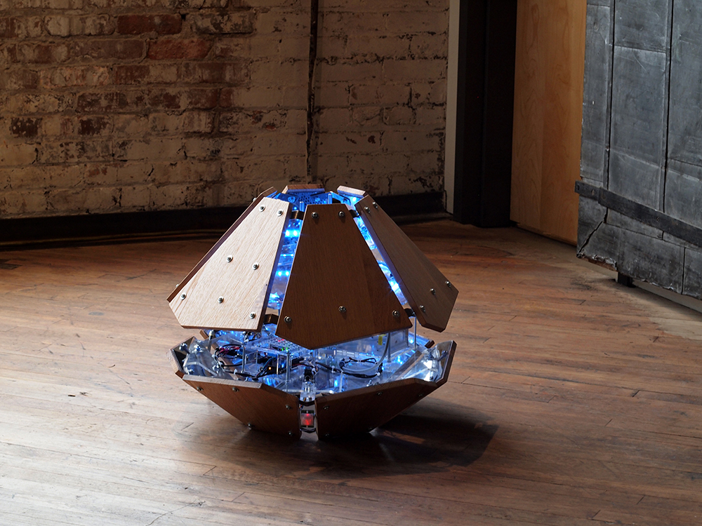
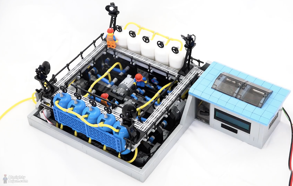
As demonstrated in the video below, this can in fact be accomplished, and in brilliant style no less. The design uses four motors, eight pneumatic pumps, and 10 air tanks to produce a pressure of 35PSI and beyond.
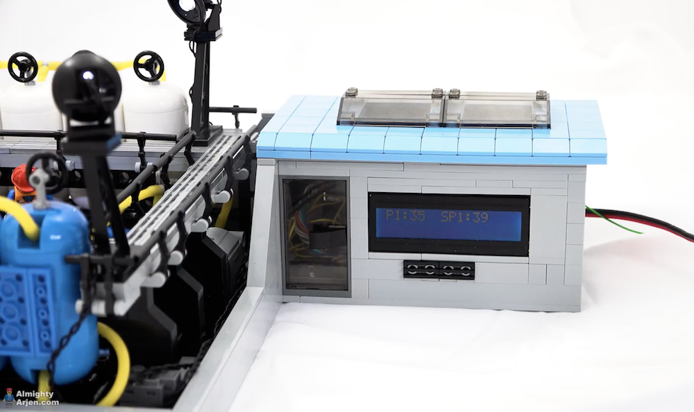
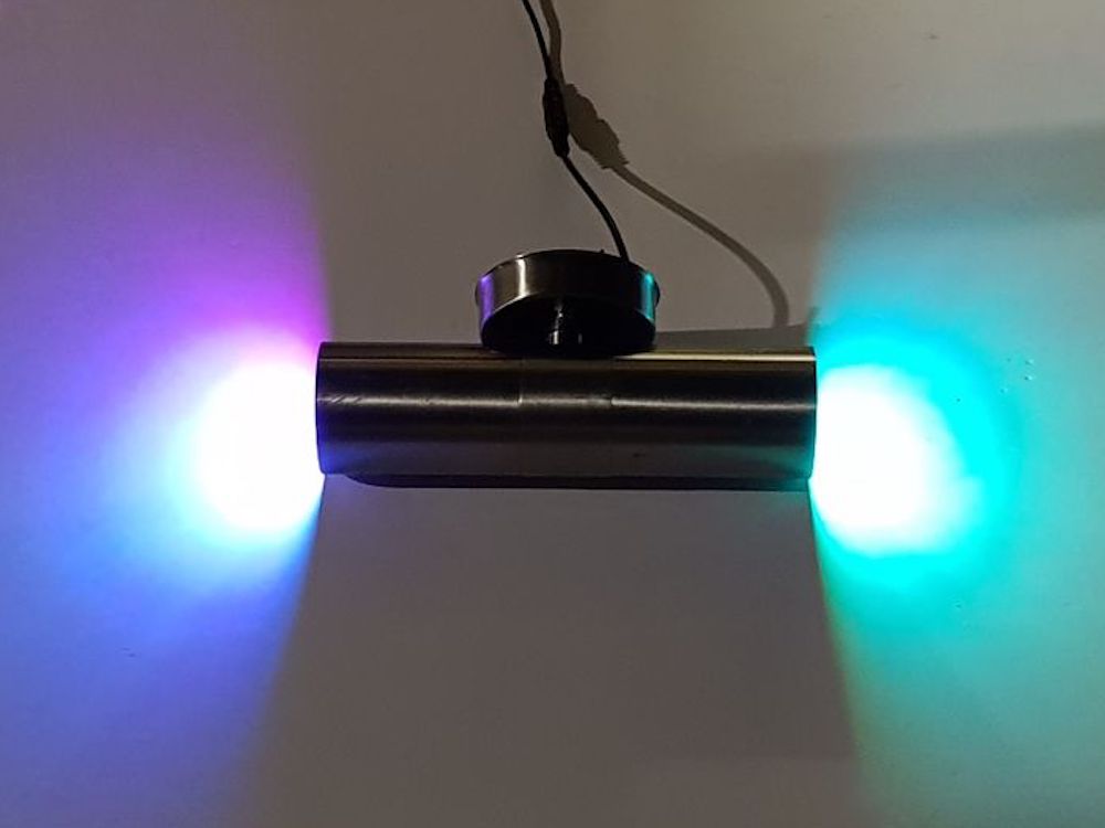
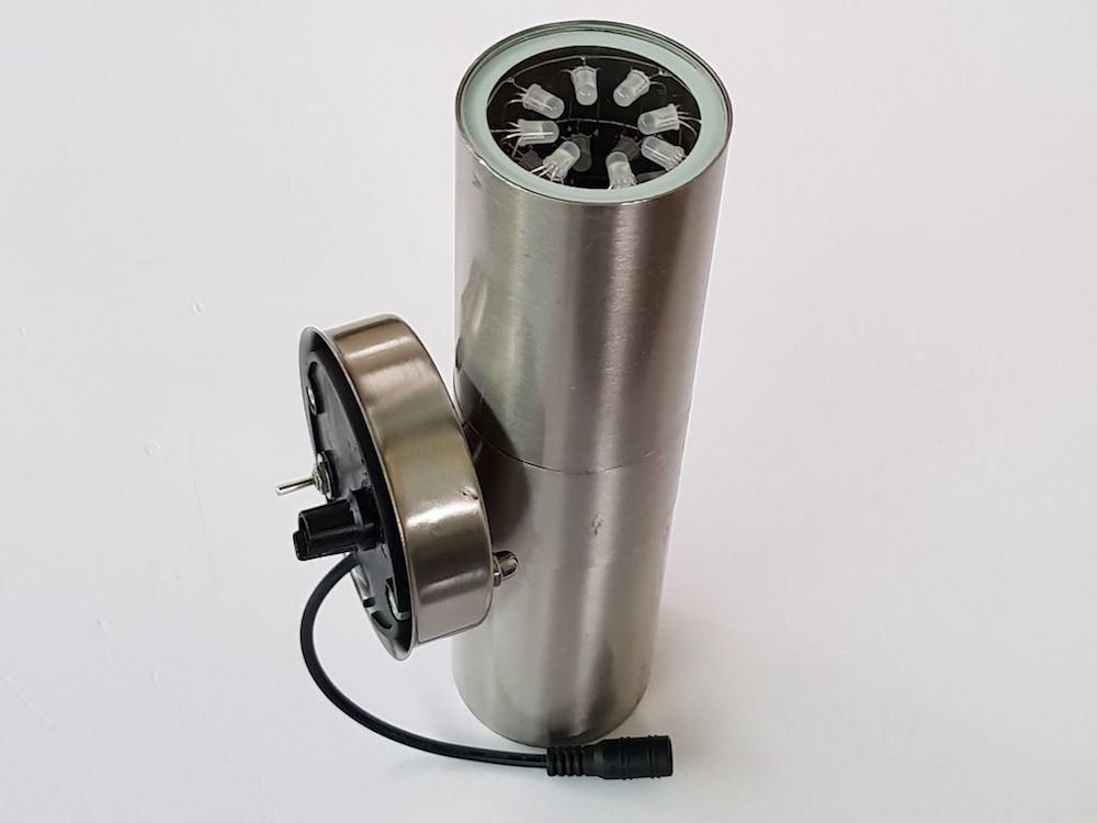
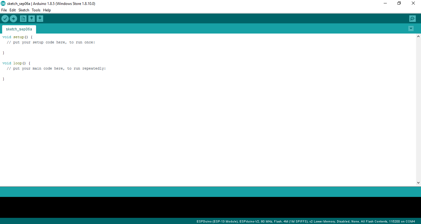
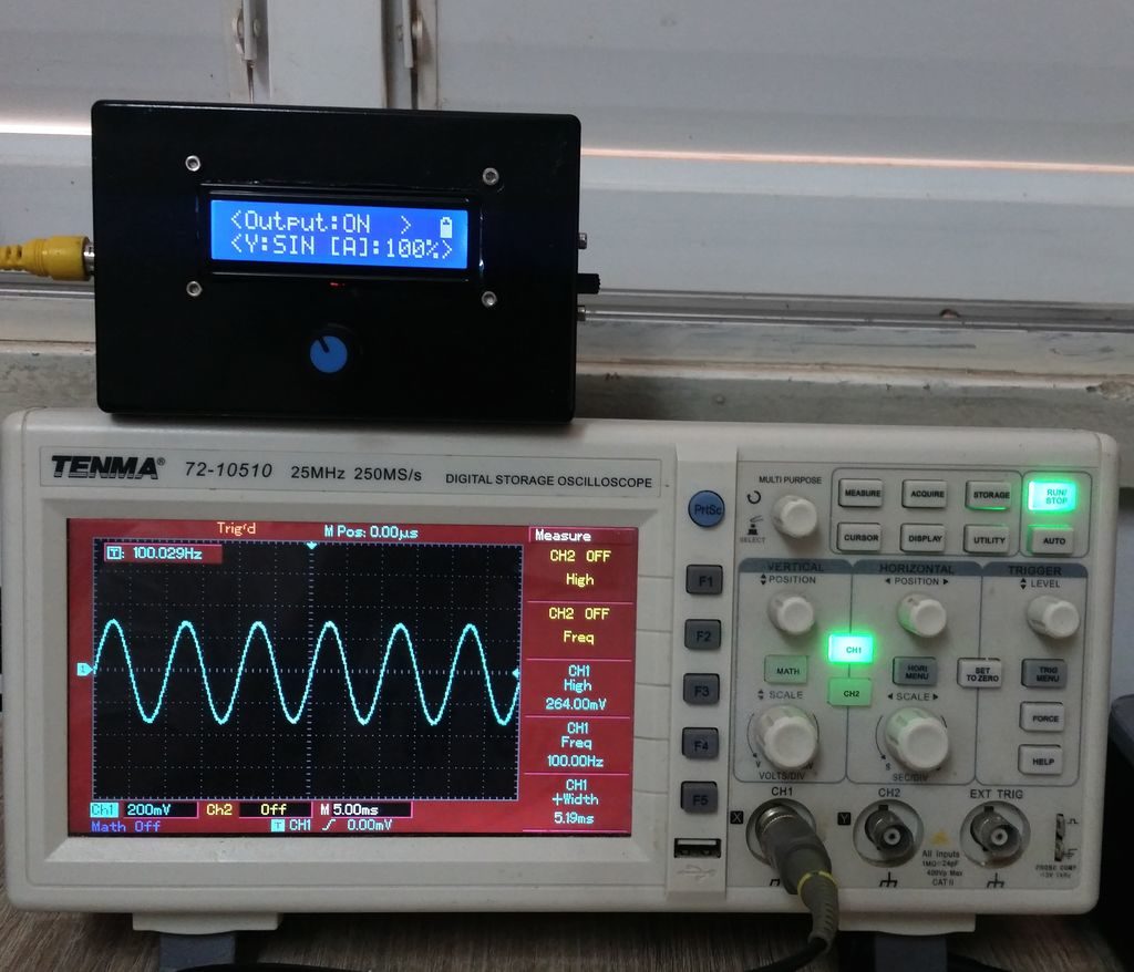
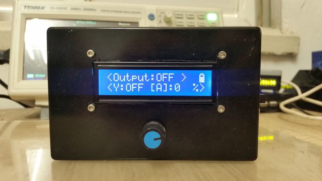
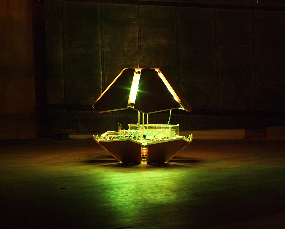
Controls consist of an Arduino board, along with a pair of resistors to set two separate tank pressures. User feedback is provided by two external displays, and the setup even features a lighting system to allow “workers” to perform maintenance access 24 hours a day!
For a quick start, the compressor has a Turbo function which is enabled under 35 psi this makes the motors run on 12V instead of the rated 9V. This way the air tanks are filled a bit faster but without overloading the motors.
The compressor has two sections which can be used separately with their own setpoint or as one big compressor. This selection is done by switching the outlet valves at the back of the compressor and by setting a jumper on the circuit board.
The Arduino control also tracks the running time of each section in hours and is shown when a switch on the circuit board is pressed.
The pressure is measured by a non official Lego pneumatic sensor by Mindsensors.com.