Posts with «arduino» label

A Star-Trek-Inspired Robot With Raspberry Pi and AI

When [314Reactor] got a robot car kit, he knew he wanted to add some extra things to it. At about the same time he was watching a Star Trek episode that featured exocomps — robots that worked in dangerous areas. He decided to use those fictional devices to inspire his modifications to the car kit. Granted, the fictional robots were intelligent and had a replicator. So you know he won’t make an actual working replica. But then again, the ones on the TV show didn’t have all that either.

A Raspberry Pi runs Tensorflow using the standard camera.  This lets it identify objects of interest (assuming it gets them right) and sends the image back to the operator along with some identifying information. The kit already had an Arduino onboard and the new robot talks to it via a serial port. You can see a video about the project, below.

The design is complicated a bit by the fact that the original kit uses a Bluetooth adapter to send and receive serial commands from a mobile device. However, the controller software with the kit, though, allows for extra buttons, so the Arduino can receive command and send them to the Pi.

The code for the robot — known as Scorpion — is available on GitHub. The extra commands relate to the camera and also some servos that move pincers to mimic the TV robot. Images return to the operator via the Telegram cloud service.

We have to admit, the Scorpion isn’t quite the same as an exocomp. But we can see the influence on the design. It wasn’t smart enough to identify itself in the mirror, so we don’t think it achieved sentience.

We’ve seen smart robots using Tensorflow before. If you prefer, you can always try OpenCV.
OpenLH robot automates biological exploration

If you’d like an easy way to accomplish repetitive biological experiments, the OpenLH presents a great option for automating these tasks. 

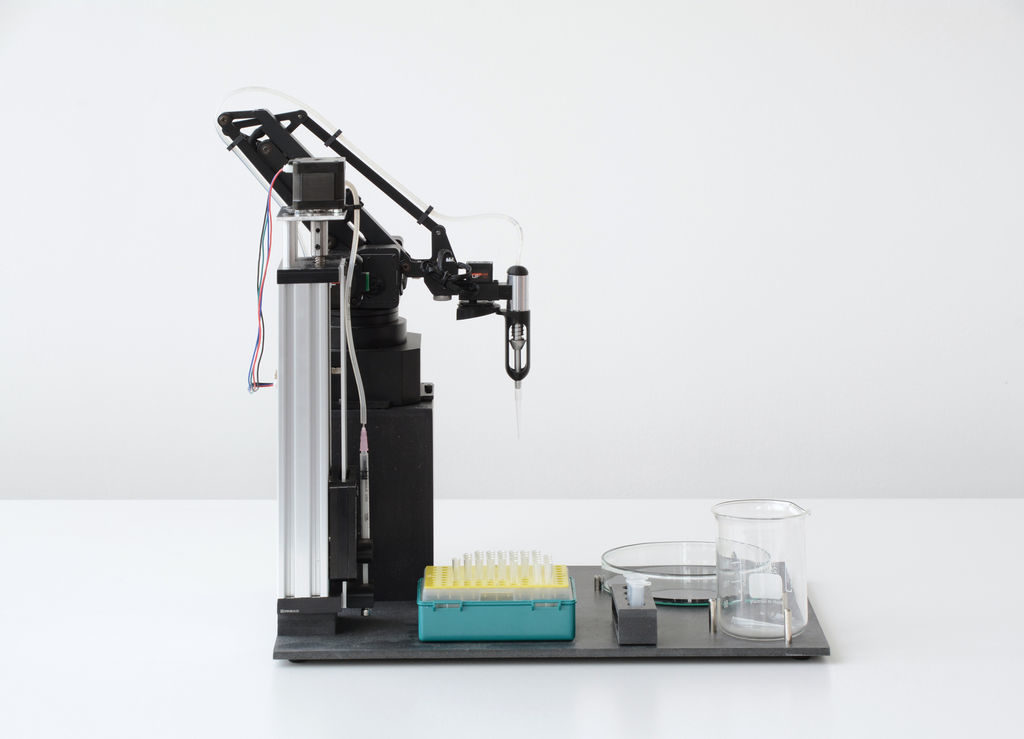
The heart of the system is the Arduino Mega-controlled uArm Swift Pro robot, which is equipped with a custom end effector and syringe pump. This enables it to dispense liquids with an average error of just .15 microliters.

A Python/Blockly interface allows the OpenLH to be set up for creative exploration, and because of the arm’s versatility, it could later be modified for 3D printing, laser cutting, or any number of other robotic duties. 

Liquid handling robots are robots that can move liquids with high accuracy allowing to conduct high throughput experiments such as large scale screenings, bioprinting and execution of different protocols in molecular microbiology without a human hand, most liquid handling platforms are limited to standard protocols.

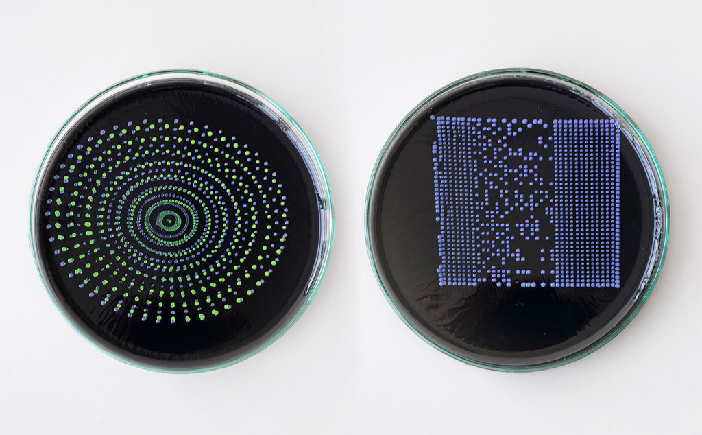
The OpenLH is based on an open source robotic arm (uArm Swift Pro) and allows creative exploration. With the decrease in cost of accurate robotic arms we wanted to create a liquid handling robot that will be easy to assemble, made by available components, will be as accurate as gold standard and will cost less than $1,000. In addition the OpenLH is extendable, meaning more features can be added such as a camera for image analysis and real time decision making or setting the arm on a linear actuator for a wider range. In order to control the arm we made a simple Blockly interface and a picture to print interface block for bioprinting images.

We wanted to build a tool that would be used by students, bioartists, biohackers and community biology labs around the world.

The OpenLH can be seen in the video below, bioprinting with pigment-expressing E. coli bacteria.

A First Look at Sony’s Spresense

The Spresense development board is Sony’s debut into the Maker market for microcontrollers, and it’s an impressive one.

Read more on MAKE

The post A First Look at Sony’s Spresense appeared first on Make: DIY Projects and Ideas for Makers.

An inexpensive device for analyzing roasted coffee beans

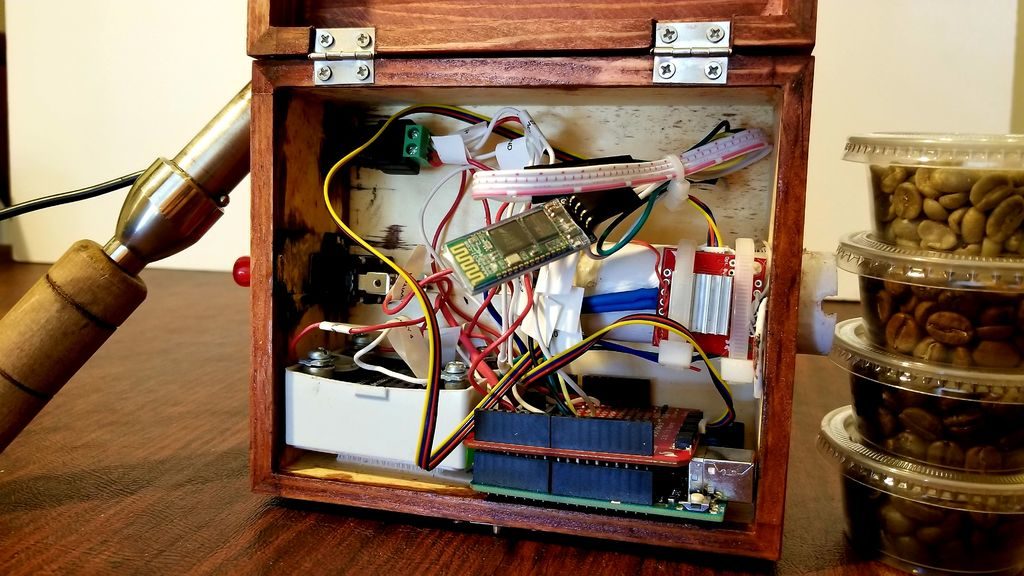
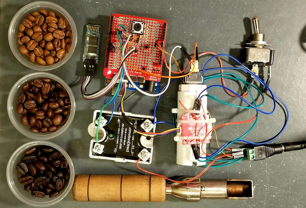
While you may not consider in detail how your coffee is roasted, those that produce it must pay special attention to make sure that the end product is consistent. Equipment to help analyze roasted coffee is normally quite expensive, but using a near-infrared sensor, Arduino Uno and Bluetooth module, Spencer Corry was able to make his own analysis setup.

As shown in the video below, after calibration, beans are inserted into the analysis chamber using a tryer scoop. Light is shined onto the roasted beans, and the intensity of the reflected near-infrared radiation is analyzed in six different wavelengths. Intensity data is then transmitted via Bluetooth to a smart device, which can be used to make sure things are roasted perfectly.

There has recently been a growth of small roasting companies offering custom in-house roasts. These companies are looking for less expensive alternatives to hiring and training a roast master or using the expensive Agtron Process Analyzer. The Degree of Roast Infrared Analyzer for Coffee Roasters, as described in this document, is meant to be an inexpensive means of measuring the degree of roast of coffee beans. The Degree of Roast Infrared Analyzer uses a tryer, a tool found on coffee roasters used to sample the coffee during roasting, to hold a sample of coffee. The tryer is inserted into the analyzer where the AS7263 NIR Spectral sensor is used to measure 6 different infrared bands (610, 680, 730, 760, 810, and 860nm). The reflectance measurements are transmitted via Bluetooth and can then be correlated to the degree of roast. The analyzer must first be calibrated by pressing a button on the inside of the box in which the PVC is used as a white balance as it has a relatively flat reflectance in the spectral range detected by the sensor.

A multi-matrix scrolling text display for absolute beginners

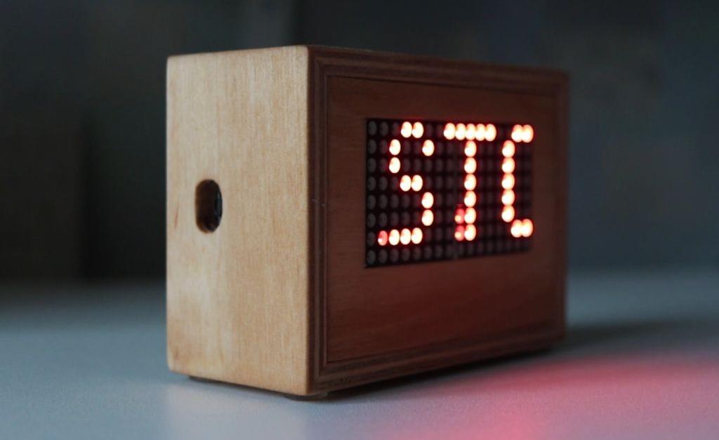
For this build, YouTuber DIY Perspective goes through the process of constructing a scrolling text display with two 8×8 matrices. 

His instructions, along with an excellent video, go through the process from the very basics, including things that many would take for granted, like installing the Arduino IDE. For this reason, it could be a great introduction for those that are new to the maker electronics scene.

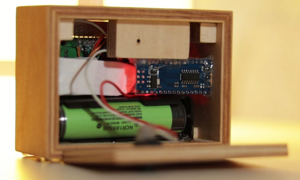
The device is controlled via an Arduino Nano and can be powered by an 18650 battery or wall charger. While relatively simple electronics-wise, what really sets this project apart is the beautifully finished wooden enclosure. It’s held together with glue, and nicely sealed with a single screw!

Welcome Our New Insect Overlords With Arduino-Powered Ant Bot

Walking robots come in many forms, and each presents their own unique challenges. Bipedal style locomotion is considered particularly difficult to do well, however designs with more legs offer certain advantages. Hexapods offer the possibility of keeping several legs on the ground while others move, providing a useful degree of stability. [How To Mechatronics] developed this ant robot, which is an excellent example of the form.

The hexapod has as the name suggests, six legs, each of which consist of 3 joints. This necessitates 3 servos per leg, for 18 servos total just for locomotion. Further servos are then used to control the abdomen, head, and mandibles. This gives the robot strong ant credentials, above and beyond being simply a 3D printed lookalike.

Brains come courtesy of an Arduino Mega, chosen for its ability to control a large number of servos. A custom PCB is printed as a shield to ease the connection of all the necessary hardware. An HC-05 Bluetooth module is used for communication with an Android app, which controls the ant. The piece de resistance is the ultrasonic sensors in the head, which allow the ant to automatically defend itself against predators that get too close.

It’s an involved build, requiring plenty of 3D printing and over 200 fasteners. Fundamentally though, it’s a fully working and tested hexapod build with full plans available for download, ready to toil in your underground sugar caves.

If your hexapod tastes skew more anime than insectoid, check out this Ghost in the Shell build. Video after the break.

[Thanks to Baldpower for the tip!]

Hack a Day 18 Dec 00:00

Button, Button, Who’s Got the (One) Button?

We often think that less is more, but what can you do with a device that has only a single button? [Volos] wondered the same thing and he built an Arduino with a single button and a display. After doing some obvious things  (like a counter or stopwatch) he decided to make a calculator.

You can find the source code online and he used a library from GitHub to handle the reaction to single presses, double presses, and long presses. Is it ideal? Probably not. But if you only have a limited amount of space or pins, it can make the difference between a feasible project and one you can’t finish.

His original projects also included a Flappy Bird clone. The OLED display is only 64×48 so that’s not a lot of room. The packaging of the tiny Arduino, the battery, and the display in a good looking case, was pretty impressive. So the device might be usable for something.

Of course, the library will work with any program and there’s no reason you can’t have more than one button and simply multiply their functions with the same strategy. There’s a sample on GitHub that shows how you can create two OneButton objects connected to different hardware devices.

By the way, the little box may have only one button, but it also has a power switch. Turns out, you can use it as an input in certain circumstances. If the OLED display strikes you as too luxurious, try the DUO BINARY.

An Arduino-based rocket motor thrust test stand

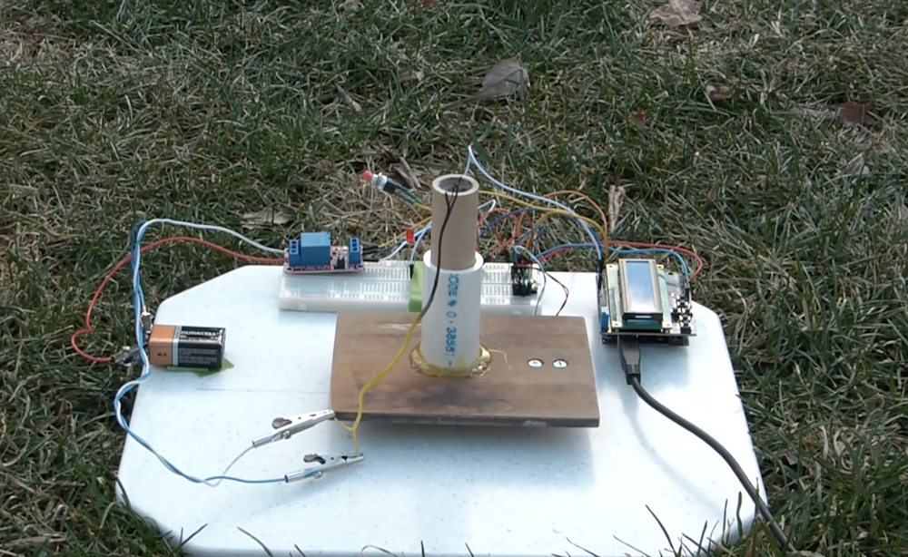
If you enjoy model rocketry, you may wonder just what the thrust curve of the motors you’re using looks like. In order to answer that question, YouTuber ElementalMaker decided to construct his own test stand using an Arduino Uno coupled to a 10Kg load cell with an HX711 amplifier board. The test procedure is started with a little red button, and after warning LED blinks away for 10 seconds, it activates a relay and fires the motor under into the stand.

The experimental setup seen in the video yields successful thrust curves for both a ½ inch and ¾ inch motor. As you might expect, the ¾ produces more thrust than its smaller cousin, though at 2,683 grams versus the ½ inch motor’s 658, it’s an impressive difference indeed. 

The heart of the stand is a common load cell (the sort of thing you’d find in a digital scale) coupled with a HX711 amplifier board mounted between two plates, with a small section of vertical PVC pipe attached to the topmost plate to serve as a motor mount. This configuration is capable of measuring up to 10 kilograms with an 80Hz sample rate, which is critically important at this type of rocket motors only burn for a few seconds to begin with. The sensor produces hundreds of data points during the short duration of the build, which is perfect for graphing the motor’s thrust curve over time.

Given such a small window in which to make measurements, [ElementalMaker] didn’t want to leave anything to chance. So rather than manually igniting the motor and triggering the data collection, the stand’s onboard Arduino does both automatically. Pressing the red button on the stand starts a countdown procedure complete with flashing LED, after which a relay is used to energize a nichrome wire “electronic match” stuck inside the motor.

The project is based on a paper archived here if you’d like to examine the design.

Build a single-pixel scanning camera with an RGB sensor

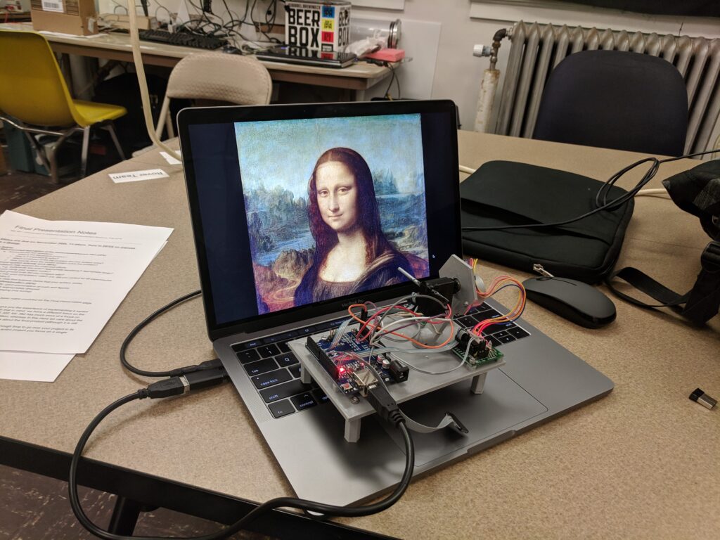
Sensors like the TCS34725 from Adafruit can detect a single color. It stands to reason then, that if you were to aim this sensor at a multitude of points and record the resulting data, you could have a one-pixel camera. As seen here, Tucker Shannon decided to take this concept and run with it, constructing his own with an Arduino Uno and a pair of stepper motors.

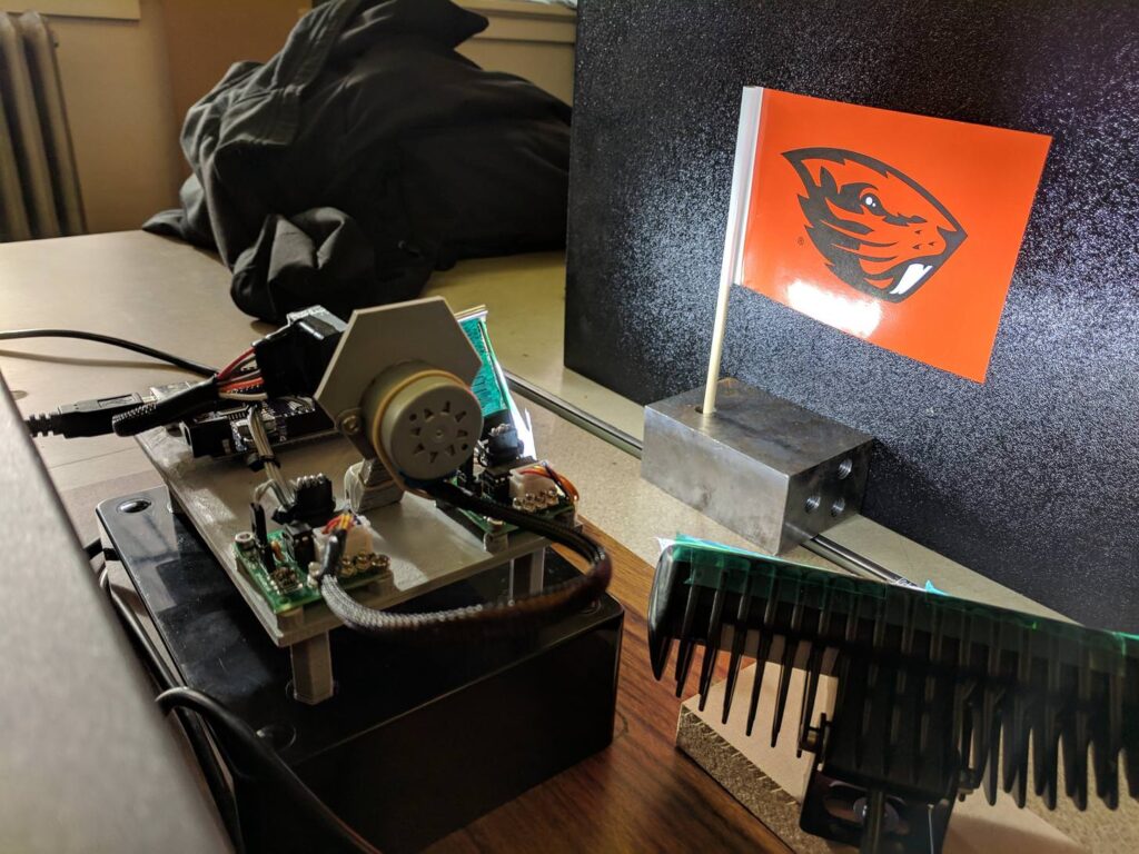
The device looks like something akin to some sort of auto-turret, and directs the sensor in a square spiral for image acquisition. The resulting pictures are certainly low-res, but good enough to pick out recognizable forms with a little imagination. 

The color sensor tells the Arduino what color it “sees” at any given time. By pointing it at every single point within a field of view, I can record these colors and use them later to reconstruct an image.

Using two stepper motors, the camera points the sensor at every “pixel” within the photo and records what it sees. It uses these values to “paint” a picture of whats in front of it!

Components include: 1x Arduino Uno, 1x Adafruit RGB Color Sensor TCS34725, x2 BYJ-48 Stepper motor with drivers, x1 3mm OD aluminum tube, x20 M3x6mm fasteners. Alternatively a photoresistor can be used in place of the RGB sensor for black and white photos!

Code for the project can be found on GitHub, and print files are on Thingiverse if you’d like to build your own!

Drone morphs into the perfect shape in mid-air

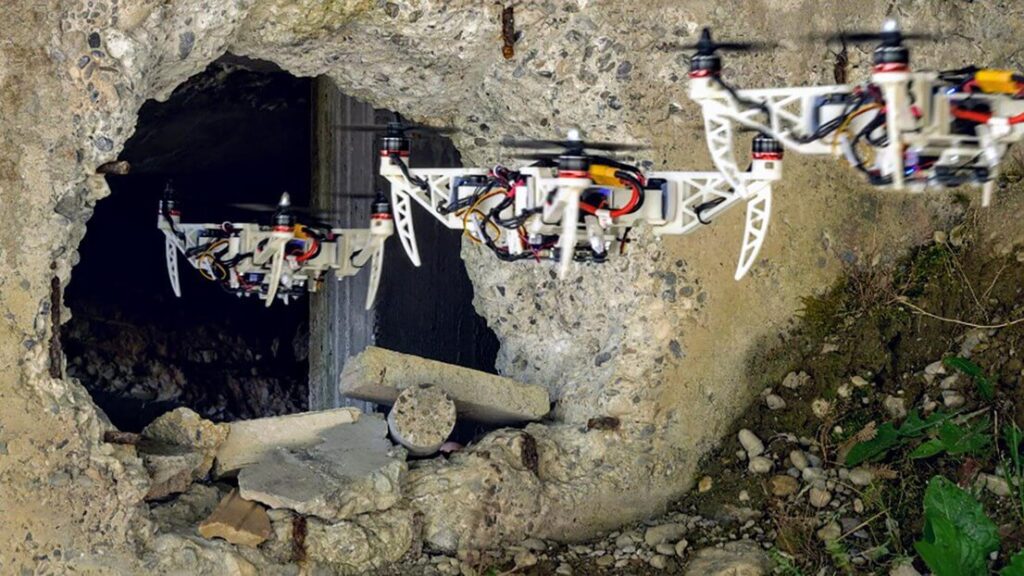
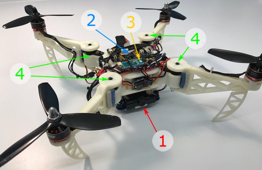
Drones come in many shapes and sizes, but for the most part their motor pods are fixed during flight. Inspired by the way birds can fold their wings, researchers from the University of Zurich and EPFL have come up with a quadcopter capable of changing motor orientation dynamically in mid-air. This allows the nominally X-shaped drone to fold itself into tight spaces, and even configure itself for optimal handling.

Flight control is handled by an advanced Snapdragon quad-core computer, while the servos that actuate the motor arms are controlled using an Arduino Nano. 

An interview about the project is available on IEEE Spectrum, while the Foldable Drone’s research paper, along with several more videos, can be found here.