Description
'Tis the season to be jolly, but sometimes you would like to tone down the jolliness. Or perhaps you are the designated driver and need to know how festive that punch is !
I have the perfect solution for you:
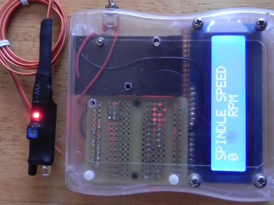
The grove alcohol sensor.
Most people look to buy this sensor to make their own DIY breathalyser. Don't bother. You won't get the accuracy you are looking for, or you probably won't have all the necessary equipment/materials required to calibrate it. While you can get a rough idea, I would NOT recommend using this sensor to make any decisions based on quantitative measurements.
I will also point out that this sensor is not specific for Alcohol. It will react to some other chemicals too. In other words, you cannot assume that a positive result equates to the presence of alcohol (ethanol) in the air. It could be butane, LPG, Isopropanol etc etc.
This project will attempt to show how much alcohol is in the air, for the sole purpose of identifying the presence, as well as getting a rough estimate of the strength of alcohol, in a variety of festive drinks.
PLEASE NOTE:
Do not submerge the sensor in liquid, and avoid splashing the sensor. Also do not expose the sensor to strong chemicals (including alcohol) for extended periods. There is a 48 hour burn-in time for this sensor. Which means that it actually performs better once it has been used for over 48 hours. The sensor also needs to warm up, which often takes more than 15 minutes long. Once exposed to a strong concentration of alcohol in the air, the sensor takes what seems like an eternal amount of time to recover. Take this into consideration when planning your future project.
Arduino IDE
While there are many Arduino IDE alternatives out there, I would recommend that you use the official Arduino IDE for this project. I used the official Arduino IDE app (v1.8.5) for Windows 10.
Make sure to get the most up-to-date version for your operating system here.

Libraries required
The following libraries will be used in the Arduino code:
- Wire.h
- math.h
- rgb_lcd.h
The
Wire.h library is used for I2C communication, for the Grove LCD screen.
The
math.h library is used for the pow() function, to calculate the concentration of alcohol in the air.
The
rgb_lcd.h library simplifies the operation of the LCD screen.
The Wire.h and math.h library are already within the Arduino IDE, no further download or installation required. However, you will need to install the rgb_lcd.h library - which can be
downloaded from GitHub. Once you download the zip file, install it into the Arduino IDE:
- Load the Arduino IDE
- Navigate to Sketch >Include library > Add .ZIP library...
- Select the downloaded zip file from GitHub, and press the "Open" button
- Check that it installed correctly by navigating to File > Examples > Grove-LCD RGB Backlight
Arduino Code
If the Grove-LCD RGB Backlight option is available in the examples folder, then you are good to go.
Select File > New
Paste the following code into the Arduino IDE, and upload it to the Arduino UNO (or compatible board).
PLEASE NOTE: Make sure the Alcohol Sensor is NOT connected to the Arduino while uploading your code to the Arduino. It seems to interfere with Serial communication for some reason, and the renders the COM port unusable until you reset the board, reboot the IDE and/or your computer. The best way to avoid this issue, is to unplug the Alcohol sensor from the Grove Base shield, ANY time you upload code to the Arduino.
Connection instructions
Now that the code has been uploaded, it is now time to make the necessary connections from the Arduino to the Grove 16x2 LCD module, and also to the Grove Alcohol sensor.
- Disconnect the USB cable from the Arduino to remove power.
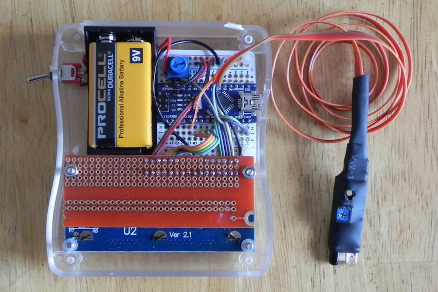
- Install the Grove Base Shield (v2) onto the Arduino UNO. The header pins on the Base shield should line up exactly with female headers of the Arduino. Please make sure that there are no stray or misaligned pins that are unaccounted for by the Arduino board.
- Set the Base Shield Switch to 5V. The switch is in the corner near the LED on the Base Shield.
- Connect one end of the 4-pin cable to A0 connector on the Grove Base Shield, and the other end of the cable to the Grove Alcohol Sensor module.
- Connect one end of a 4-pin cable to an I2C connector on the Grove Base Shield, and the other end of the cable to the Grove 16x2 LCD module.
- You can now apply power to the Arduino Board via the power jack or the USB cable.

Connection Table
Arduino to Grove Alcohol Sensor module
The Grove Alcohol sensor operates off 5V.
If you are using the Grove Base Shield, place the switch to 5V.
Disconnect the Alcohol sensor from the base shield when uploading code to the Arduino.
Arduino to Grove 16x2 LCD module
The Grove 16x2 LCD module can operate off 5V or 3.3V.
I used 5V from the Arduino UNO.
Project Explained
When the Arduino is powered up, you will be presented with a message, "Alcohol Project by ArduinoBasics". This is a splash screen to introduce the project.
The heater pin on the Alcohol sensor is then activated, which can cause the program to hang. If you do not see the message "Heater Activated", and only see a blank LCD screen - reset the Arduino board. There is a reset pin on the Base shield next to the LED. This message will only display for about 3 seconds before it starts to take readings from the Alcohol sensor.
I am guessing that each sensor is different, however, I found that the sensor worked best, once it had been in use for over 48 hours. I normally wait for the sensor reading to get above 5 or 6 before exposing it to alcohol fumes. You will notice the readings slowly increase over time. Wait until the readings stabalise, which can take anywhere between 15-20 minutes, or longer if the sensor has not been used for a while.

In the presence of alcohol fumes/vapour, the sensor readings will drop, and will trigger the Arduino to change the display to show the rough concentration of alcohol in the Air. Do not expose the sensor to strong concentrations of alcohol for extended periods, as this may permanently affect the sensor performance thereafter. I cannot tell you what readings are NORMAL, because I only have one sensor, and have nothing to compare it to. I have seen my sensor reading get to 11.96, but have noticed that the maximum reading changes each time I test it (sometimes higher, sometimes lower). I am guessing that the surrounding environmental conditions will affect this maximum (i.e. temperature / humidity / air quality), and also the length of time the sensor has had to "burn in" for.
Once you reach the maximum value (or as long as you are willing to wait), go ahead and test it out. Hover the sensor over the suspiciously alcoholic festive punch, and catch out your sneaky grandmother.
Conclusion
The biggest learning points for me about using the Grove Alcohol sensor, was how surprisingly long it took for the sensor to stabalise, and I guess how impatient I am. These types of sensors are often advertised as being a way to create your own breathalyser. But I quickly found out just how hard that was, and after my experience with the sensor, I would never contemplate using it for that purpose, because I cannot verify the accuracy of the results.
Can it detect alcohol in the air? Yes it can. The Grove Alcohol sensor can give a rough estimate of the concentration of alcohol vapour in the air, and at best, I would say that it gives you a semi-quantitative result. The same sensor will detect butane, LPG, petrol, isopropanol fumes - which is good or bad, depending on what you plan to use it for.
One of the most common ways of reading the Alcohol results is through the Serial monitor. However, the Alcohol sensor would for some reason lock up or freeze the Serial communication. I found the best way to observe readings from the Alcohol sensor was to use a Grove LCD module.
The Grove LCD module was very easy to use and enabled a more portable project. Grove modules are generally very easy to connect to the Grove Base shield, and are very much "plug and play". The Universal 4pin cables, reduce the "rats-nest" of wires - endemic to Arduino projects.
I hope this tutorial has helped you somewhat. If you use this project, please let me know your experience with it in the comments below, and even better, tell me who you caught out.
If you found this tutorial helpful, please consider supporting me by buying me a virtual coffee.