Arduino Fights Fire with… Water?
We don’t think we’d want to trust our fire safety to a robot carrying a few ounces of water, but as a demonstration or science project, [Tinker Guru’s] firefighting robot was an entertaining answer to the question: “What do I do with that flame sensor that came in the big box of Arduino sensors I bought from China?” You can see a video of the device below.
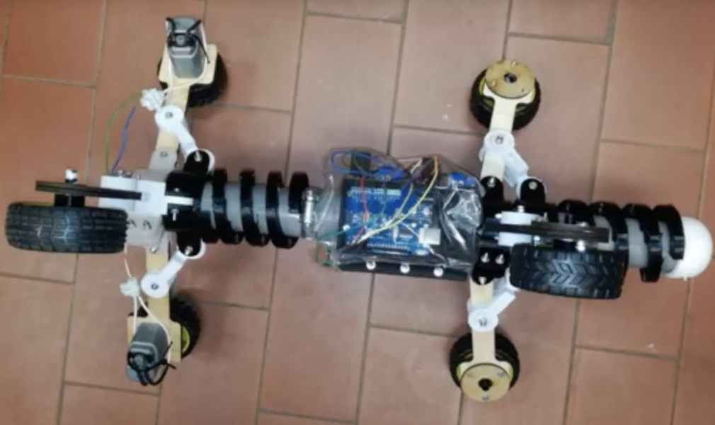
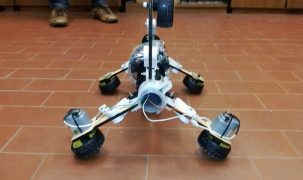
You can see, it is a pretty standard two-wheel robot with the drive wheels to the rear and a skid plate up front. There are a flame sensor and a water pump up forward, as well. You can probably guess, the device notices a flame and rushes to squirt water on it.
That got us thinking, though. What would it take to build a real robot fireman? Turns out you don’t have to look hard to find out there are several out there already. The Thermite robot seems to have a lot of traction — in the market, that is, although its oversized treads probably give it good traction in that way, too. Most of the robots don’t carry their own water, and there’s even one — THOR — that looks like a human. Well, as much as a pie looks like a cake, anyway.
Interestingly, none seem to carry any sort of chemical fire extinguisher. Of course, we’ve seen cases where water was the best, anyway. If you want a slightly more practical home build — but only slightly — check out [Ivan’s] robot that holds a liter of water.
 The project uses the TPA81 8-pixel thermopile array which detects the change in heat levels from 8 adjacent points. An Arduino reads these temperature points over I2C and then a simple thresholding function is used to detect the movement of the fingers. These movements are then used to do a number of things including turn the volume up or down as shown in the image alongside.