Janus: The Gatekeeper
[Piet] wrote in to tell us about his hack that allows for his front gate to be opened without a key. Unlike this hack that we featured in August, you don’t need a subway pass, just a good memory. As explained in his article (and the video after the break) if the proper sequence of doorbell rings is input, the gate unlocks itself.
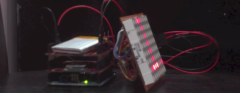
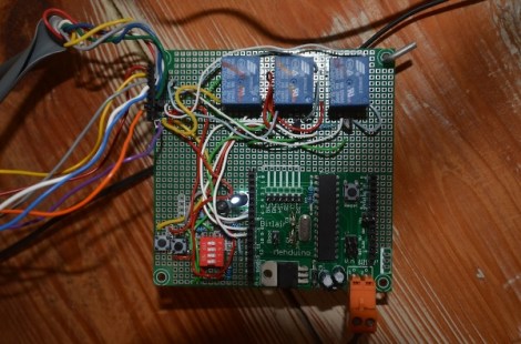
For hardware a [mehduino] is used to take the doorbell input and decide whether or not the “secret knock” has been achieved. The door can be unlocked remotely via a button on the processor. Reprogramming the code is achieved by simply holding the program button while the code is entered on the “remote ringer” button.
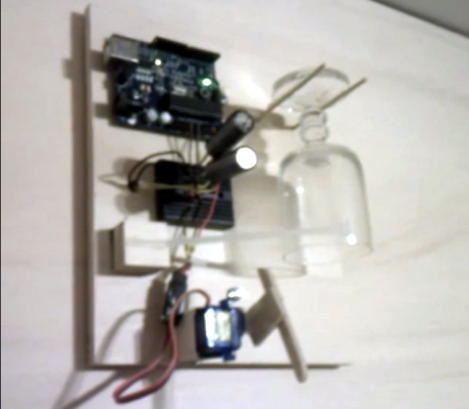
Be sure to check out the video after the break to see this lock in action. The housing application may not be exactly what you expect. Also of interest, is that in true hacker fashion, the bare processor is hanging by a hook on his wall!
Filed under: arduino hacks, lifehacks