Let’s face it — eating different colored candy like M&Ms or Skittles is just a little more fun if you sort your pile by color first. The not-fun part is having to do it by hand. [Jackofalltrades_] decided to tackle this time-worn problem for engineering class because it’s awesome and it satisfies the project’s requirement for sensing, actuation, and autonomous sequencing. We’d venture to guess that it satisfies [Jackofalltrades_]’ need for chocolate, too.
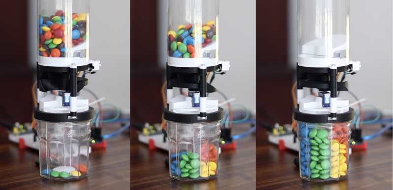
Here’s how it works: one by one, M&Ms are selected, pulled into a dark chamber for color inspection, and then dispensed into the proper cubby based on the result. [Jackofalltrades_] lived up to their handle and built a color-detecting setup out of an RGB LED and light-dependent resistor. The RGB LED shines red, then, green, then blue at full brightness, and takes a voltage reading from the photocell to figure out the candy’s color. At the beginning, the machine needs one of each color to read in and store as references. Then it can sort the whole bag, comparing each M&M to the reference values and updating them with each new M&M to create a sort of rolling average.
We love the beautiful and compact design of this machine, which was built to maximize the 3D printer as one of the few available tools. The mechanical design is particularly elegant. It cleverly uses stepper-driven rotation and only needs one part to do most of the entire process of isolating each one, passing it into the darkness chamber for color inspection, and then dispensing it into the right section of the jar below. Be sure to check out the demo after the break.
Need a next-level sorter? Here’s one that locates and separates the holy grail of candy-coated chocolate — peanut M&Ms that didn’t get a peanut.
We’ve all been there. Your current project has hit a wall, or the next step will take days to complete, and you need something to do in the meantime. So you start a project that you envision will fit nicely in the gap, and then, inevitably, it doesn’t. Maybe it even takes so long that the original project gets finished first. So what? There’s nothing wrong with that, especially when the filler project turns out as well as this drink temperature monitor disguised as a circuit sculpture (video, embedded below). Just put your mug on the coaster, and the weight of it activates a hidden switch, which causes the sculpture to display its secret LEDs.
[MakeFunStuff] wanted to make something that looked less like a circuit and more like art, while building a tool that could determine the relative hotness of a beverage. Such a a useful circuit sculpture sounds like a tall order to us, but [MakeFunStuff] pulled it off with finesse and style.
The circuit is based around this Sputnik-looking standalone IR temperature sensor which, as [MakeFunStuff] aptly describes, is “a single-pixel infrared camera that picks up everything in a 90° cone starting at the sensor.”
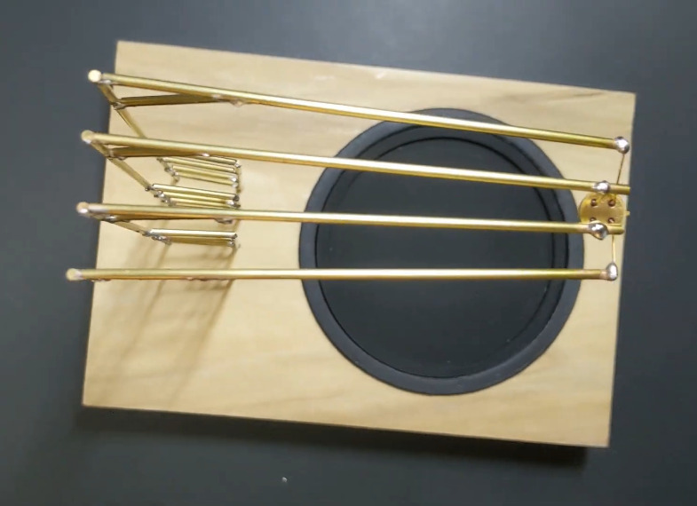
[MakeFunStuff] paired this easy-to-use sensor with an Arduino Nano and five LEDs that show how hot a beverage is on a scale from 1 to 5. The sensor is hidden in plain sight, suspended from the top of the brass rod sculpture and blending in perfectly. We love that the LEDs are hidden behind a thin layer of carefully-drilled wood and agree that a drill press would have been much easier.
The code is set up for just about every temperature scale from Celsius to Rømer, so that solves that argument. [MakeFunStuff] went with the Kelvin scale because science. Our favorite thing about this video is that [MakeFunStuff] shared their failures and fixes as they built their way toward answering the questions of how to suspend the sensor over the drink, and how best to display the heat level while hiding the electronics. Go grab a hot cup of something and check it out after the break while you let it cool off the normie way.
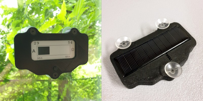
The past year has been quite a ride for everyone on Earth. But you never know which day is going to be your last, so you might as well live a little, eh? This clock doesn’t actually know when you’ll kick off, either. But just for fun, it predicts the number of years remaining until you go to that hackerspace in the sky by hazarding a guess that’s based on your current age and the latest life expectancy tables. Don’t like the outcome? It’s completely randomized, so just push the button and get a set of numbers: the age you might die, and the percentage of life elapsed and remaining.
We love the design of this calculated doom clock, and it’s quite simple inside — an Arduino Pro Mini outputs the graph on an 2.9″ e-paper display, and both are powered with a 5.5 V solar panel. Just suction cup that puppy to the window and you’ll get automatic updates about your impending demise on sunny days, and none on cloudy days.
Ever since we saw the movie Big, we’ve wanted a floor piano. Still do, actually. We sometimes wonder how many floor pianos that movie has sold. It’s definitely launched some builds, too, but perhaps none as robust as this acrylic and wooden beauty by [FredTSL]. If you want more technical detail, check out the project on IO.
The best part is that this piano is modular and easily expands from 1 to 8 octaves. Each octave runs on an Arduino Mega, with the first octave set up as a primary and the others as secondaries. When [FredTSL] turns it on, the primary octave sends a message to find out how many octaves are out there, and then it assigns each one a number. Whenever a note is played via conductive fabric and sensor, the program fetches the key number and octave number and sends the message back to the primary Mega, which plays the note through a MIDI music shield.
We think this looks fantastic and super fun to dance around on. Be sure to check out the build log in photos, and stick around after the break, because you’d better believe they busted out some Heart and Soul on this baby. After all, it’s pretty much mandatory at this point.
There was a time when building electronics and building software were two distinct activities. These days, almost any significant electronic project will use a CPU somewhere, or — at least — could. Using a circuit simulator can get you part of the way and software simulators abound. But cosimulation — simulating both analog circuits and a running processor — is often only found in high-end simulation products. But I noticed the other day the feature quietly snuck into our favorite Web-based simulator, Falstad.
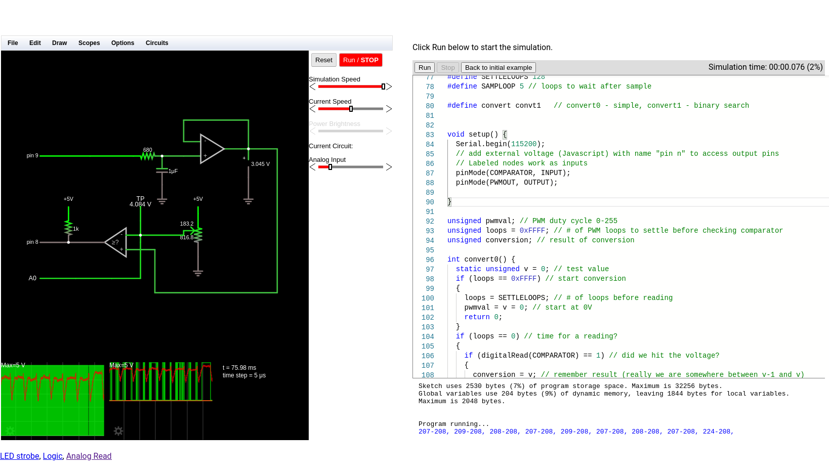
The classic simulator is on the left and the virtual Arduino is on the right.
Back in March, the main project added work from [Mark McGarry] to support AVR8js written by [Uri Shaked]. The end result is you can have the circuit simulator on the left of the screen and a Web-based Arduino IDE on the right side. But how does it work beyond the simple demo? We wanted to find out.
The screen looks promising. The familiar simulator is to the left and the Arduino IDE — sort of — is to the right. There’s serial output under the source code, but it doesn’t scroll very well, so if you output a lot of serial data, it is hard to read.
Nothing is Perfect
I love just about everything about the Falstad simulator and having an Arduino cosimulation is great. But there is one really important issue that may get resolved eventually. Normally when you draw a schematic you can save it as text or encoded in a link. If you click the link or import the text, everything is back to the way it was when you saved. I use that in a lot of Circuit VR posts so you can click on a circuit and see it live.
However, the simulator does not save the source code in the virtual Arduino. You have to do that yourself. That means if you have everything working, save your circuit, and close your browser you’ll have to recreate your Arduino code next time. Luckily, I tested this out before I lost any work. There should be a big red warning on the page, though.
What that means, though, is that I can’t give you a link to follow along with examples. Here’s what you can do:
Copy the text from the top of the source code comments and paste it into the simulator (detailed instructions in the comments).
Just don’t forget to save your source code changes. If you make changes to the circuit, you’ll want to export them to text and copy them into the source code so you can save everything together.
An Example
Test schematic.
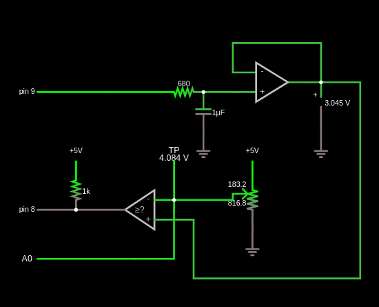
I wanted an easy example that showed the benefit of using cosimulation. I settled on looking at some alternatives for doing an analog to digital conversion using successive approximation. A virtual potentiometer provides an input voltage. There’s a comparator and a buffered PWM output. Here’s the schematic:
Input/Output
There are three interface points to the Arduino. The PWM output is set as an external voltage using the “Inputs and Sources” components (remember, the output from the Arduino is the input to the circuit). Conversely, the comparator output and the connection to the Arduino’s analog converter (A0) are labeled nodes from the “Output and Labels” menu. The names are significant, including the spaces.
The Code
In theory, the code is pretty simple. You guess a voltage and read the output of the comparator to see if you are right. There are two methods in the code and you can switch between them by setting the convert define to convert0 or convert1.
On every pass through the loop, the code calls one of the convert functions to manage the successive approximation process through a different algorithm. It also updates the PWM output on each pass.
The first approximation algorithm is very simple but not very efficient. It guesses each output voltage starting at 0 and moving up 1/255 V on each pass. When the comparator goes from false to true, you know the input voltage must be less than the current voltage but more than the previous voltage.
The second algorithm is smarter and works like a binary search. The first guess is 128/255. That voltage is either higher or lower than our target. If it is lower, we remember that the bit should be on and, either way, move to the next bit. In other words, the second test will be either 64/255 or 128/255 + Simulide64/255. Again, the new value is either high or low and will determine the state of the next bit.
The first algorithm could finish fast or it may have to count all the way to 255 to find the answer. The second algorithm always takes 8 measurements. There’s no way for the comparator to tell us our reference voltage is exactly equal to the input even if we could define what that means for an analog signal. So we have to measure each bit and decide if it should be on or off.
The output appears in the serial terminal. The first number is the result of the conversion and the second is the value from the built-in converter for the same voltage.
Voltage Reference
Generating the reference voltage is the key. It would be possible to use 8 output bits and an R2R network to generate an output voltage quickly, but that eats up a lot of pins. Instead, I used one pin to generate voltages using PWM. This isn’t as fast, of course, because you have to allow the RC filter time for the voltage to reach its desired value.
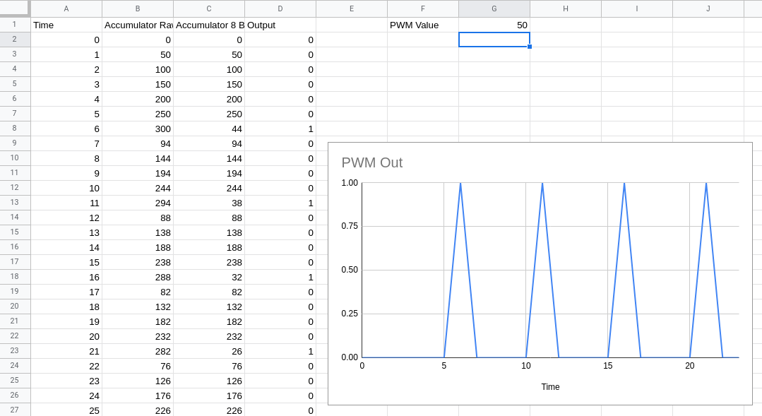
Pin 9 generates a PWM signal using a time-honored technique. Suppose you want to generate 20/255 (about 8% duty cycle). You take an 8-bit accumulator and add 20 to it repeatedly. The PWM output is the carry out of the top bit. You can find a spreadsheet with the logic, but you’ll have to imagine the output waves are squares since the spreadsheet helpfully draws straight lines between points.
This spreadsheet models the PWM output logic.
To do this right, the code should run on a precise interrupt and equalize the time between outputs. However, for this quick demo, I’ve assumed the time for calling the main loop will be regular enough. I considered doing it on an interrupt, but — honestly — I’m not sure how faithful the simulator is, how time-accurate it is, and it doesn’t appear you can easily add libraries to it, so you’d almost certainly have to manage the interrupts at the register level.
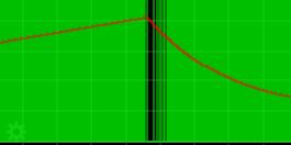
The output signal gets smoothed by an RC filter. The values here are interesting and it is fun to watch the scope as you vary the parameters in this part of the circuit. You want a noise-free reference signal. So that implies a big capacitor. However, a big capacitor takes more time to charge and discharge, so the voltage will take longer to settle. It is a classic trade-off. Do you want a noisy fast response or a clean slow response?
In this case, the pot probably doesn’t change very fast, but in real life, the input signal might be changing all the time and you might even consider a sample and hold on that input to make sure it doesn’t change while you are in the middle of guessing.
Tuning
Obviously, you can change the RC values easily in the simulator. It is even possible to add sliders to set the values graphically while the simulation is running (the pot is set up to do this already). Changing the code, however, requires a stop and restart.
In the code, you can change the number of loop cycles the convert routines wait to allow a new PWM value to settle (SETTLELOOPS) and how long to pause between readings (SAMPLOOP). The interactions between these numbers and the RC values are critical. Larger RC time constants require more time to produce correct results. Smaller RC numbers will require less time, but the noise will introduce errors. Take your pick.
PWM signal with 2uF capacitor.
PWM signal with 47uF capacitor.
The Verdict
This is a toy example. The PWM generation suffers from some issues and PWM isn’t a great idea for a conversion reference. Still, it shows a good bit of what is possible with the cosimulation available with Falstad. I am really looking forward to the next time I need some exotic signal fed into a circuit. Just using the Arduino as a function generator will have its uses.
I do wish you could add libraries and save an entire project more easily. Still, there are many what-if scenarios you could simulate quickly and easily using this tool. Since it has only been in the code base for a few months, I’m hopeful some of these issues will work out over time. Add debugging to the mix, and it would be a real winner.
Tinkercad allows you to simulate Arduino, but not with the circuit sophistication of Falstad. It does require an install, but we are always surprised we don’t hear more about Simulide.
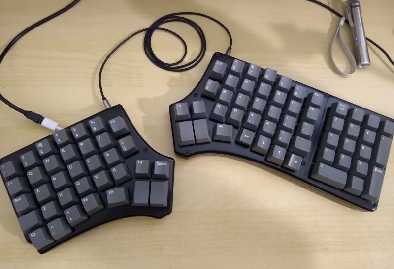
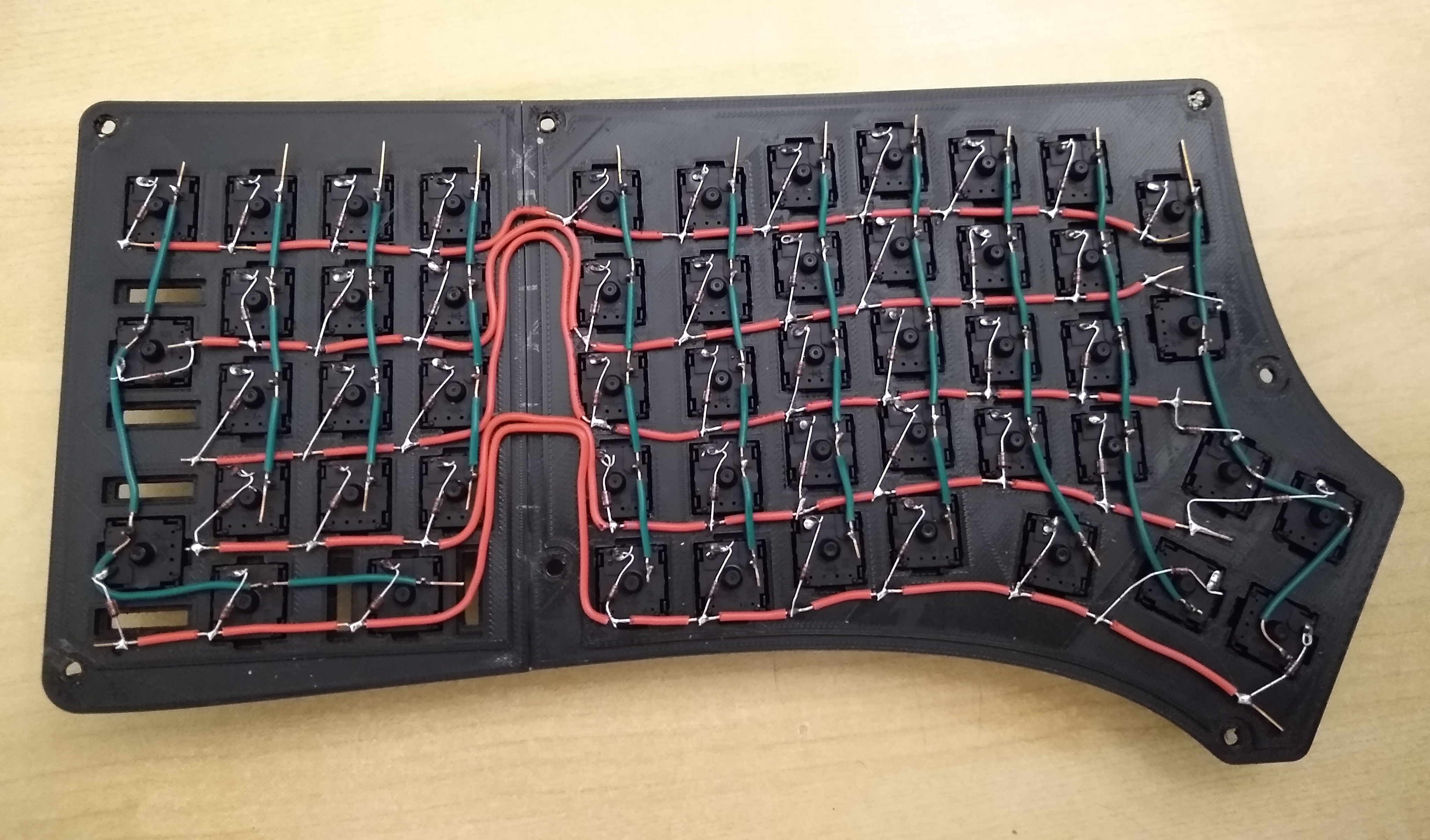
What’s the worst thing about split keyboards? If they have one general fault, it’s that almost none of them have a number pad. If you can fly on that thing, but struggle with using the top row numbers, you will miss the num pad terribly, trust us. So what’s the answer? Design your own keyboard, of course. [ToasterFuel] had enough bread lying around to cook up a little experiment for his first keyboard build, and we think the result is well done, which is kind of rare for first keebs.
This design is based on the Redox, itself a remix of the ErgoDox that aims to address the common complaints about the latter — it’s just too darn big, and the thumb clusters are almost unusable. We love how customized this layout is, with its sprinkling of F keys and Escape in the Caps Lock position. Under those keycaps you’ll find 100% Cherry MX greens, so [ToasterFuel] must have pretty strong fingers to pound those super clackers.
Everything else under the hood is pretty standard, with a pair of Arduino Pro Micros running the show. [ToasterFuel] had to wire up the whole thing by hand because of the num pad, and we’re impressed that he built this entire project in just three weeks. And that includes writing his own firmware!
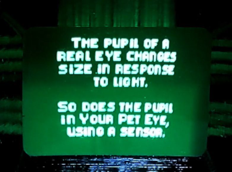
Like many of us, [Emily’s Electric Oddities] has had a lot of time for projects over the past year or so, including one that had been kicking around since late 2018. It all started at the Hackaday Superconference, when [Emily] encountered the Adafruit Hallowing board in the swag bag. Since that time, [Emily] has wanted to display the example code eyeball movement on a CRT, but didn’t really know how to go about it. Spoiler alert: it works now.
See? It’s educational.
Eventually, [Emily] learned about the TV out library for Arduino and got everything working properly — the eyeball would move around with the joystick, blink when the button is pressed, and the pupil would respond visually to changes in ambient light. The only problem was that the animation moved at a lousy four frames per second. Well, until she got Hackaday’s own [Roger Cheng] involved.
[Roger] was able to streamline the code to align with [Emily]’s dreams, and then it was on to our favorite part of this build — the cabinet design. Since the TV out library is limited to black and white output without shades of gray, Emily took design cues from the late 70s/early 80s, particularly the yellow and wood of the classic PONG cabinet. We love it!
Is Your Pet Eye the worst video game ever, as [Emily] proclaims it to be? Not a chance, and we’re pretty sure that the title still rests with Desert Bus, anyway. Even though the game only lasts until the eye gets tired and goes to sleep, it’s way more fun than Your Pet Rock. Don’t miss the infomercial/explanation/demonstration video after the break. If one video is just not enough, learn more about [Emily’s] philosophy of building weird projects from the Supercon talk she presented. It’s also worth mentioning that this one fits right into the Reinvented Retro contest.
Step sequencers are fantastic instruments, but they can be a little, well, repetitive. At it’s core, the step sequencer is a pretty simple device: it loops through a series of notes or phrases that are, well, sequentially ordered into steps. The operator can change the steps while the sequencer is looping, but it generally has a repetitive feel, as the musician isn’t likely to erase all of the steps and enter in an entirely new set between phrases.
Enter our old friend machine learning. If we introduce a certain variability on each step of the loop, the instrument can help the musician out a bit here, making the final product a bit more interesting. Such an instrument is exactly what [Charis Cat] set out to make when she created the After Eight Step Sequencer.
The After Eight is an eight-step sequencer that allows the artist to set each note with a series of potentiometers (which are, of course, housed in an After Eight mint tin). The potentiometers are read by an Arduino, which passes MIDI information to a computer running the popular music-oriented visual programming language Max MSP. The software uses a series of Markov Chains to augment the musician’s inputted series of notes, effectively working with the artist to create music. The result is a fantastic piece of music that’s different every time it’s performed. Make sure to check out the video at the end for a fantastic overview of the project (and to hear the After Eight in action, of course)!
[Charis Cat]’s wonderful creation reminds us of some the work [Sara Adkins] has done, blending human performance with complex algorithms. It’s exactly the kind of thing we love to see at Hackaday- the fusion of a musician’s artistic intent with the stochastic unpredictability of a machine learning system to produce something unique.
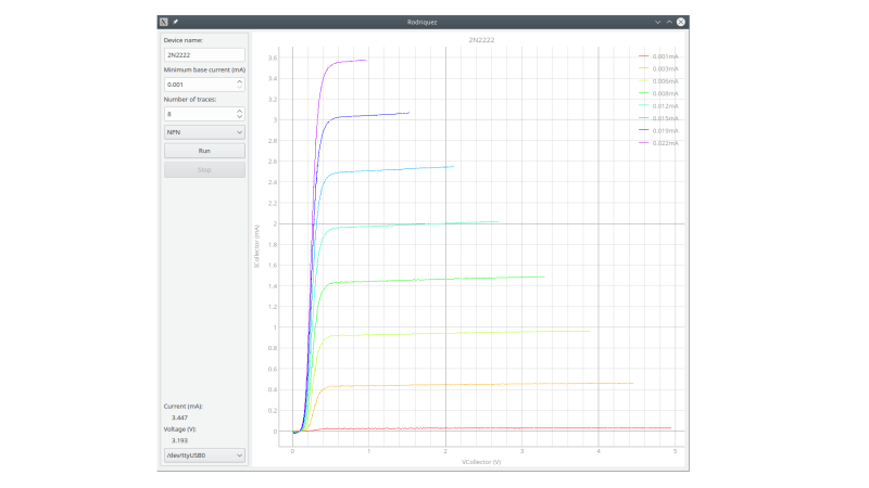
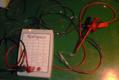
In response to an online discussion on the Electrical Engineering Stack Exchange, [Joseph Eoff] decided to prove his point by slapping together a bare-bones IV curve tracer using an Arduino Nano and a handful of passives. But he continued to tinker with the circuit, seeing just how much improvement was possible out of this simple setup. He squeezes a bit of extra resolution out of the PWM DAC circuit by using the Timer1 library to obtain 1024 instead of 256 steps. For reading voltages, he implements oversampling (and in some cases oversampling again) to eke out a few extra bits of resolution from the 10-bit ADC of the Nano. The whole thing is controlled by a Python / Qt script to generate the desired plots.
While it works and gives him the IV curves, this simplicity comes at a price. It’s slow — [Joseph] reports that it takes several minutes to trace out five different values of base current on a transistor. It was this lack of speed that inspired him to name the project after cartoon character Speedy Gonzales’s cousin, Slowpoke Rodriguez, AKA “the slowest mouse in all of Mexico”. In addition to being painstakingly slow, the tracer is limited to 5 volts and currents under 5 milliamps.
Inside this open-source banana is that perennial favorite for macro pads, the Arduino Pro Micro, and eight switches that are wired up directly to input pins. We’re not sure what flavor of Cherry those switches are, hopefully brown or green, but we suddenly wish Cherry made yellow switches. If you want to build your own, the STLs and code are available, and we know for a fact that other switch purveyors do in fact make yellow-stemmed switches.
Contrary to what the BOM says, we believe the sticker is mandatory because it just makes the build — we imagine there would be fewer double takes without it. Hopefully this fosters future fun keyboard builds from the community, and we can’t wait to sink our teeth into the split version!