MIDI Mouse Makes Marvelous Music
It’s an old misconception that digital musicians just use a mouse and keyboard for their art. This is often far from the truth, as many computer music artists have a wide variety of keyboards/synths, MIDI controllers, and “analog” instruments that all get used in their creative process. But what if one of those instruments was just a mouse?
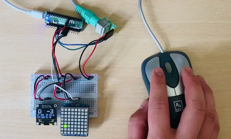
Well, that must have been what was going through [kzra]’s mind when he turned an old ps/2 roller ball mouse into an electronic instrument. Born out of a love for music and a hate for waste, the mouse is a fully functional MIDI controller. Note pitch is mapped to the x-coordinate of the pointer, and volume (known as velocity, in MIDI-speak) is mapped to the y-coordinate. The scroll wheel can be used as a mod wheel, user-configurable but most often used to vary the note’s pitch. The mouse buttons are used to play notes, and can behave slightly differently depending on the mode the instrument is set to.
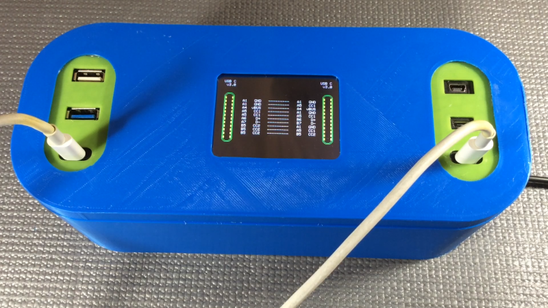
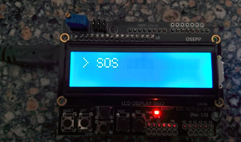
Not satisfied with simply outputting MIDI notes, [kzra] also designed an intuitive user interface to go along with the mouse. A nice little OLED displays the mode, volume, note, and mouse coordinates, and an 8×8 LED matrix also indicates the note and volume. It’s a fantastic and versatile little instrument, and you’ve gotta check out the video after the break to see it for yourself. We’ve seen some awesome retro-tech MIDI controllers before, and this fits right in.
Thanks to [midierror] for the tip!