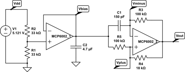
Capacitive sensing with op amps and Capacitive sensing with op amps, continued used a rather complicated circuit to make a Schmitt-trigger oscillator out of op amps:
Modified circuit for longer period. C1 is just the stray capacitance of the touch sensor, with no deliberately added capacitance.
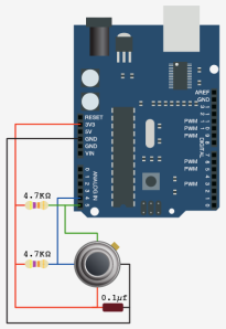
But if we use an off-the-shelf Schmitt trigger chip (like a 74HC14), then a very simple circuit can be made to oscillate:
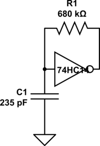
Schmitt-trigger oscillator.
Without a touch sensor, it oscillates at about 10 kHz. With an untouched touch sensor, the frequency drops to about 9.5 kHz. With a touched sensor, the frequency drops further to around 6.7 kHz. I can make the touch sensor have a bigger relative frequency change by reducing the capacitor to 157pF (3 470pF in series), from 15kHz down to 8kHz. This oscillator works fine with the code I wrote for the op-amp oscillator. Neither the resistor nor the capacitor values are particularly critical (as long as the addition of about 140pF from the touch drops the frequency enough to be measurable).
The Schmitt trigger is a useful device for students to learn about, since hysteresis is an important concept in detecting signals. In fact, it might not be a bad idea to have the code that detects the frequency and turns the LED on or off have some hysteresis, as code that just uses a time-out for debouncing tends to make the LED flash on and off when a near-touch is done.
This circuit is too simple for a full 3-hour lab. It can be wired in a couple of minutes and tested in a few more. I’ll have to think of other things to do with a Schmitt trigger to make this into a full lab. Perhaps this could be an Arduino programming lab, where they start with just a simple pulseIn program and make some modifications:
void setup(void)
{  pinMode(2,INPUT);
   pinMode(13,OUTPUT);
}

void loop(void)
{
    uint8_t on = (pulseIn(2,HIGH) >= 50) ;
    digitalWrite(13, on);
}
Perhaps a simple hysteresis program:
void setup(void)
{  pinMode(2,INPUT);
   pinMode(13,OUTPUT);
}

void loop(void)
{   digitalWrite(13, LOW);
    while (pulseIn(2,HIGH) <= 50) {}
    digitalWrite(13, HIGH);
    while (pulseIn(2,HIGH) >= 40) {}
}
Students would have to measure their oscillator waveforms on the oscilloscope, then play with the constants in the code to get reliable switching. It’s still not a 3-hour lab, but it gives another view of hysteresis.
I’ll have to think about this some more.
Filed under:
Circuits course Tagged:
Arduino,
bioengineering,
capacitive touch sensor,
circuits,
course design,
op amp,
Schmitt trigger,
sensors,
teaching