

Hysteresis lab
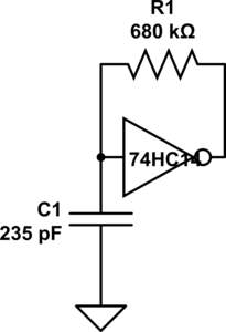
Schmitt-trigger oscillator.
Since I decided in Capacitive sensing with Schmitt trigger to use an off-the-shelf Schmitt trigger chip (like a 74HC14) and a very simple oscillator, I needed to rethink the lab and expand it. Students will no longer be spending much time on building the circuit, so we need to play with other uses for the oscillator circuit and other applications of Schmitt triggers.
The Schmitt trigger is a useful device for students to learn about, since hysteresis is an important concept in detecting signals. Probably the first thing to have them do is to use the oscilloscope in x-y mode to see the Vout vs. Vin curve for the Schmitt trigger inverter. It would be good for them to devise a way to measure the threshold voltages accurately (with their lab writeup describing both the method used and the thresholds measured), using the equipment they have available. Perhaps bonus points for methods that don’t require any of the bench equipment? (There are some fairly easy methods using the Arduino for voltage measurements, though precision would be limited to about 5mV.)
After characterizing the inverter, they should design and measure one-inverter oscillators for different frequencies, using different combinations of resistors and capacitors (some low-resistance, high-capacitance designs and some high-resistance, low-capacitance designs). They should show computations for the frequency using the threshold voltages and the R and C values. It might be worthwhile to have them estimate the parasitic capacitance of the input to the Schmitt trigger (together with the wiring).
Then they should measure capacitance by hooking up an unknown capacitor with a known resistance, measuring the frequency, and computing the capacitance. We would have to make up some unknowns with a wide range of different values.
Finally, they should make a capacitive touch pad (a piece of aluminum foil covered with a layer of packing tape). I’ve decided that I like foil covered with packing tape better than foil wrapped in plastic wrap. The tape may be a bit thicker, but the lack of an air bubble makes for a much more repeatable capacitance, and it is less likely to fall apart when handled.
They should use the oscillator frequency to estimate the capacitance of both the plain pad and the pad when touched by a finger. After observing the oscillator output on the oscilloscope they should adjust the parameters of a simple hysteresis program to turn an LED on and off with the touch sensor so that a firm touch is needed to light the LED and it doesn’t flicker with a light touch:
void setup(void)
{  pinMode(2,INPUT);
   pinMode(13,OUTPUT);
}

void loop(void)
{   digitalWrite(13, LOW);
    while (pulseIn(2,HIGH) <= 60) {}
    digitalWrite(13, HIGH);
    while (pulseIn(2,HIGH) >= 45) {}
}
Filed under: Circuits course Tagged: Arduino, bioengineering, capacitive touch sensor, circuits, course design, Schmitt trigger, sensors, teaching


[original story: Gas station without pumps]