Description
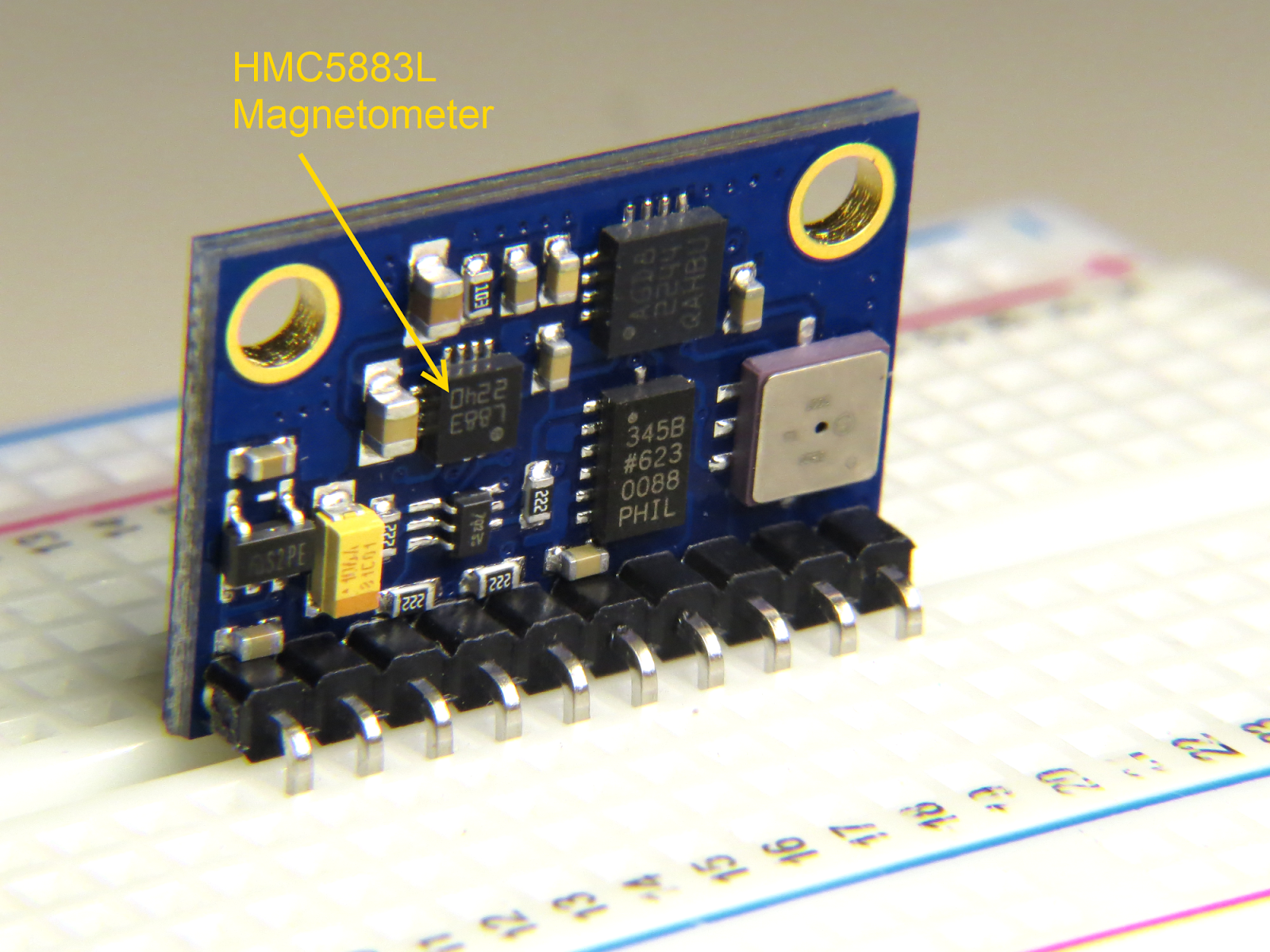
In this tutorial, I will show you how to configure and extract data from the magnetometer (HMC5883L) sensor on the GY-80 10DOF module from ICStation. While there are some very good libraries on the internet which will give you full access to this sensor, I will show you what you need to know without using a library. This means that it may get a bit technical at times, but I will hold your hand along the way and provide explanations as required. I would also recommend that you watch the complete video from start to finish - as the video provides really useful information.
HMC5883L Magnetometer Datasheet:
You can find the datasheet for the HMC5883L pretty easily by searching on the internet. Here are a couple of sources:
Arduino Libraries
This tutorial does not use any external libraries.
It does use the Wire library for I2C communication.
However, there is no extra download required to access the Wire library.
If you are looking for a library specific for the HMC5883L sensor, then I would recommend one of these:
Like I said - you do not need an HMC5883L library for this tutorial. The libraries above are listed for those who wish to learn more about this particular sensor.
Arduino IDE
The Arduino IDE can be downloaded from the Arduino website. Visit the Arduino IDE download page.
I generally use the ZIP file for Windows and never seem to have any issues.
There are downloads available for all the major operating systems.
ARDUINO CODE:
I have created a Gist for the Arduino code to configure and extract data from the HMC5883L sensor. However, I also have a GitHub repository which aims to capture the code for all of the sensors on the GY-80 module. Code for the other sensors will become available in due time. Meanwhile, have a look at the code below for the HMC5883L sensor:
This code will set all axis values to 1000 upon startup. Moving the GY-80 module around will result in a value greater or less than 1000, however, returning the sensor back to it's original position, should result in values very close to 1000 on each axis. I chose to introduce this calibration in order to avoid negative values, and I liked the fact that I could set a heading with values that were easy to remember.
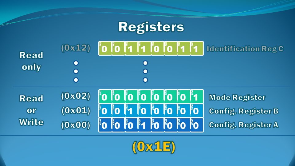
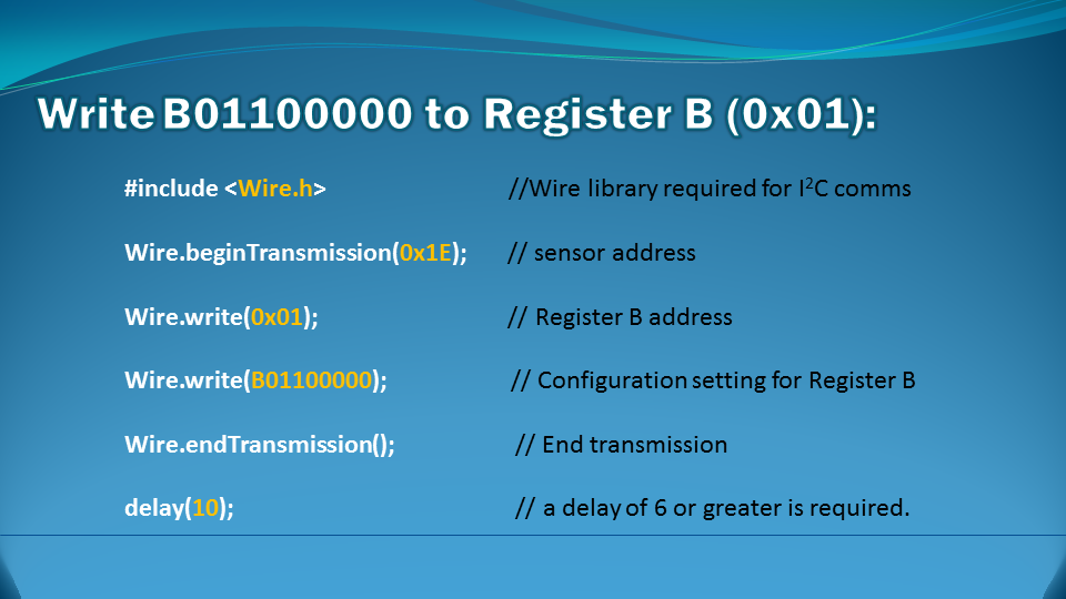
The magSetting function was created to easily configure the magnetometer.
Make sure to look at the video and also the datasheet for further information about calibrating the magnetometer.
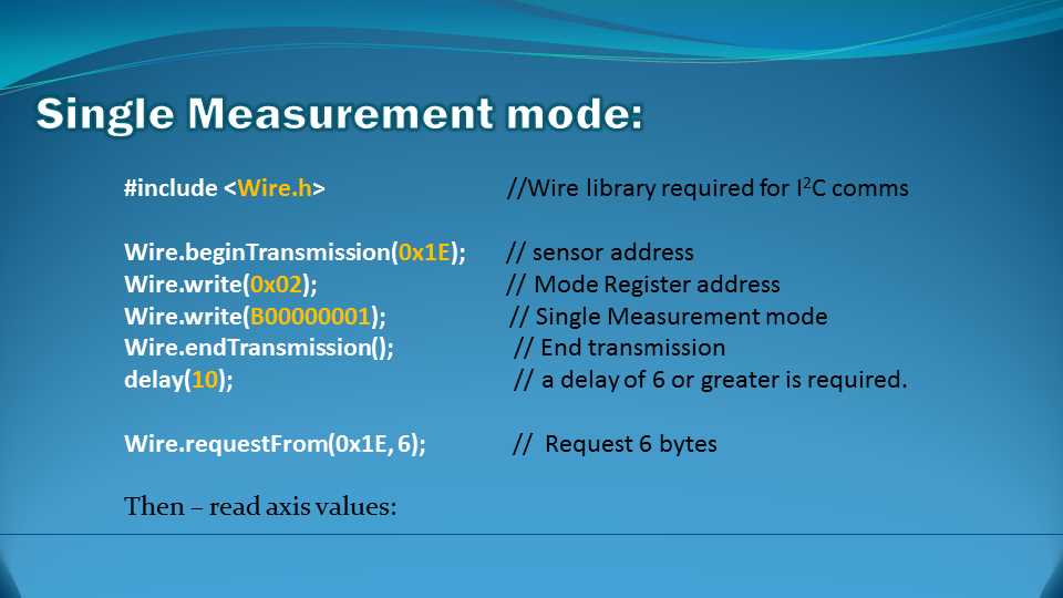
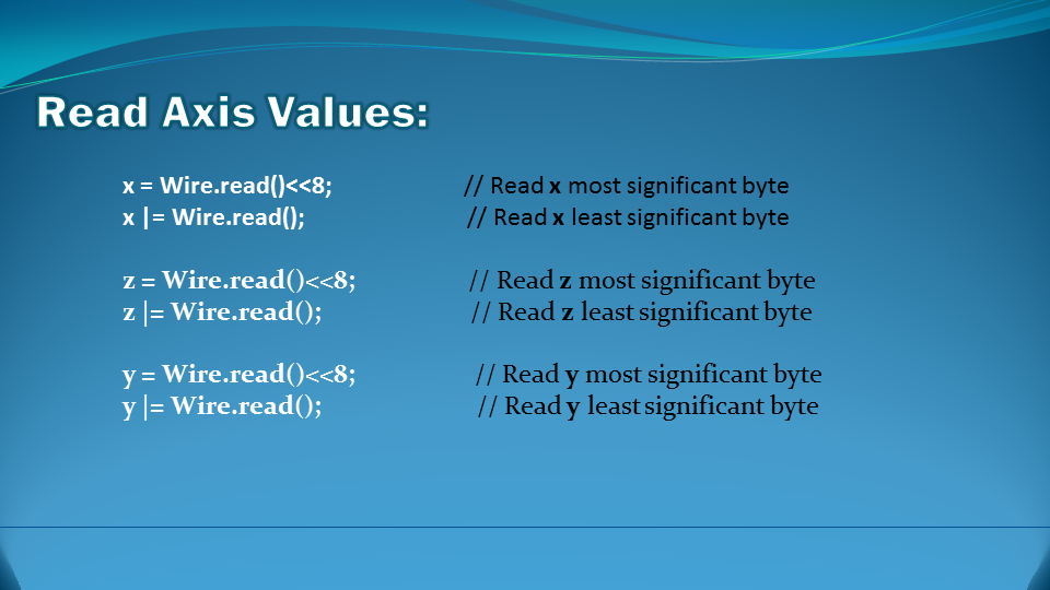
The getReadings function was created to easily retrieve the magnetometer axis data. I chose to use Single measurement mode in this tutorial.
Hooking it up:
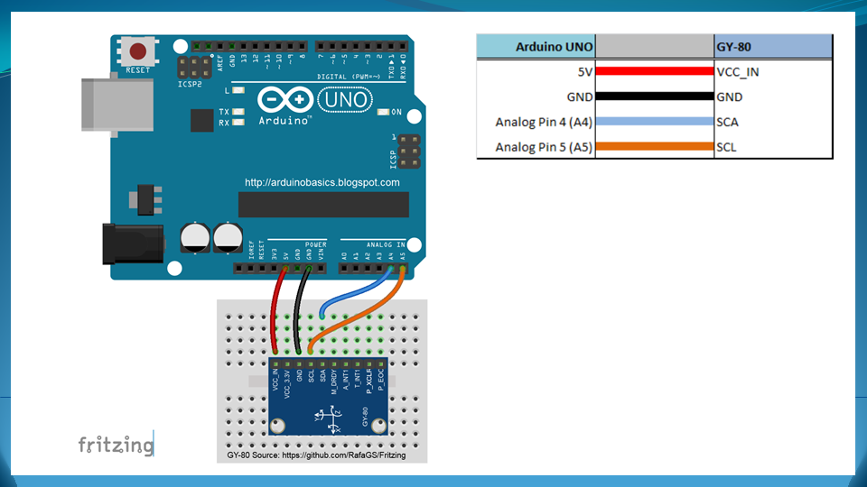
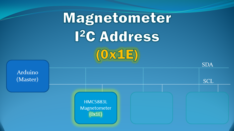
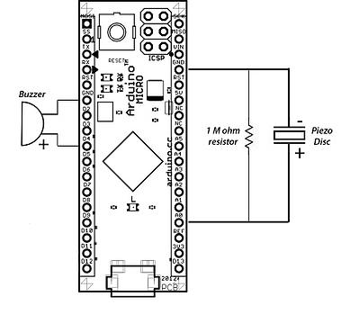
You can communicate with any of the sensors on the GY-80 module using I2C. The HMC5883L magnetometer sensor is no different. You will need four connections between the Arduino UNO and the GY-80 module. Have a look at the diagram below for the connection diagram and table.
Fritzing diagram
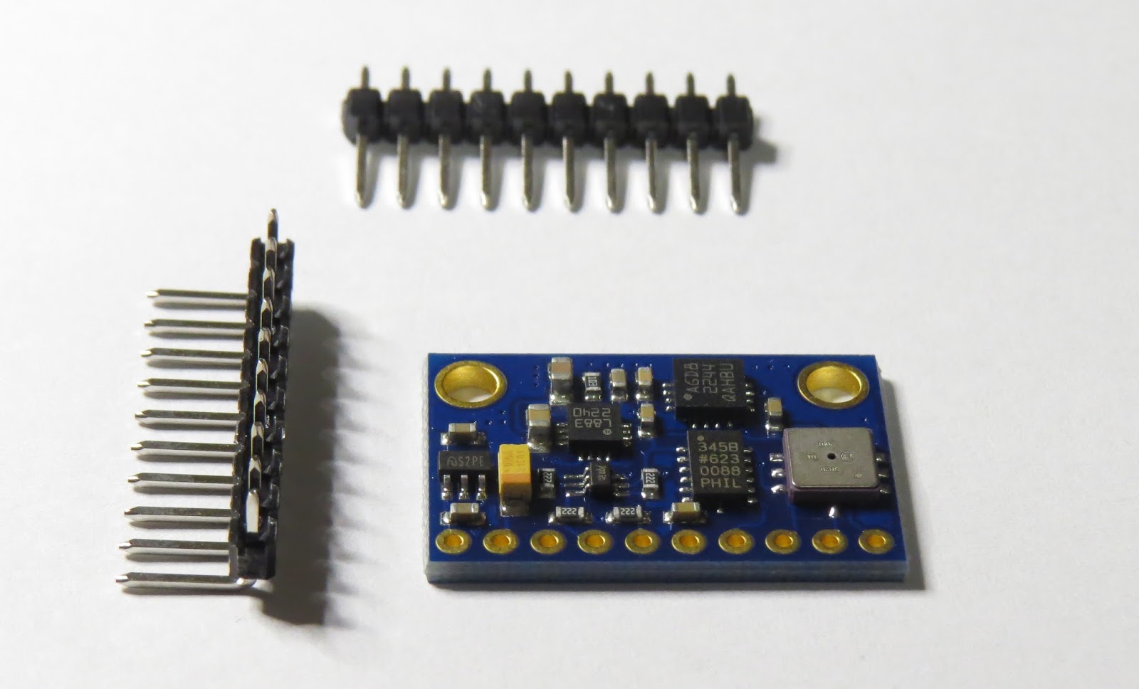
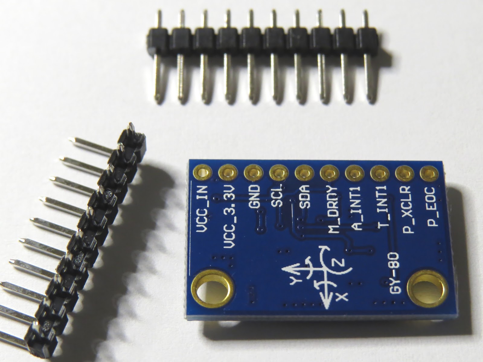
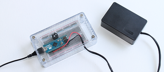
Project pictures
Concluding comments
The HMC5883L sensor on the GY-80 module is quite interesting and works relatively well. There are a number of other sensors on the GY-80 module which can provide complementary positional data. At some point, I plan to come back and explain some of the other sensors on this module, but first I would like to create a real-life project using the magnetometer. So stay tuned. You may want to subscribe to my social networks or to this blog to be notified of that project when I complete it.
I would like to thank ICStation for their collaborative efforts. Their contribution was invaluable to this tutorial's existence.


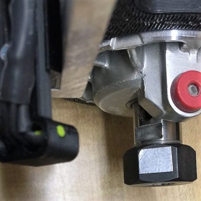 The CNC router in question is the popular Sienci, and the 3D-printed brackets for the photodiode and LED are somewhat specific for that machine. But [tmbarbour] has included STL files in his exhaustively detailed write-up, so modifying them to fit another machine should be easy. The sensor hangs down just far enough to watch a reflector on one of the flats of the collet nut; we’d worry about the reflector surviving tool changes, but it’s just a piece of shiny tape that’s easily replaced. The sensor feeds into a DIO pin on a Nano, and a small OLED display shows a digital readout along with an analog gauge. The display update speed is decent — not too laggy. Impressive build overall, and we like the idea of using a piece of PLA filament as a rivet to hold the diodes into the sensor arm.