Posts with «microcontrollers» label

Automated Watering Machine Has What Plants Crave: Fertilizer

We’ve seen countless automated plant care systems over the years, but for some reason they almost never involve the secret sauce of gardening — fertilizer. But [xythobuz] knows what’s up. When they moved into their new flat by themselves, it was time to spread out and start growing some plants on the balcony. Before long, the garden was big enough to warrant an automated system for watering and fertilizing.

This clever DIY system is based around a 5L gravity-fed water tank with solenoid control and three [jugs] of liquid fertilizer that is added to the water via peristaltic pump. Don’t worry, the water tank has float switches, and [xythobuz] is there to switch it off manually every time so it doesn’t flood the flat.

On the UI side, an Arduino Nano clone is running the show, providing the LCD output and handling the keypad input. The machine itself is controlled with an ESP32 and a pair of four-channel relay boards that control the inlet valve, the four outlet valves, and the three peristaltic pumps that squirt out the fertilizer. The ESP also serves up a web interface that mimics the control panel and adds in the debug logs. These two boards communicate using I²C over DB-9, because that’s probably what [xythobuz] had lying around. Check out the demo video after the break, and then go check on your own plants. They miss you!

Don’t want to buy just any old peristaltic pumps? Maybe you could print your own.

Portrait of a Digital Weapon

Over the years, artists have been creating art depicting weapons of mass destruction, war and human conflict. But the weapons of war, and the theatres of operation are changing in the 21st century. The outcome of many future conflicts will surely depend on digital warriors, huddled over their computer screens, punching on their keyboards and maneuvering joysticks, or using devious methods to infect computers to disable or destroy infrastructure. How does an artist give physical form to an unseen, virtual digital weapon? That is the question which inspired [Mac Pierce] to create his latest Portrait of a Digital Weapon.

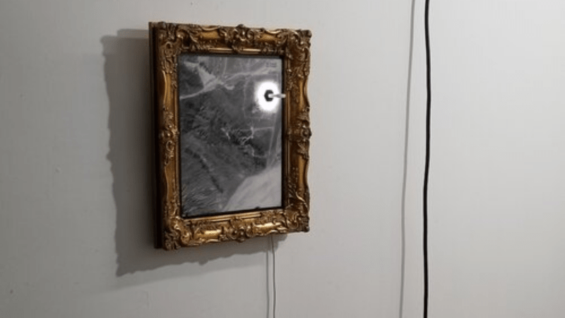
[Mac]’s art piece is a physical depiction of a virtual digital weapon, a nation-state cyber attack. When activated, this piece displays the full code of the Stuxnet virus, a worm that partially disabled Iran’s nuclear fuel production facility at Natanz around 2008.

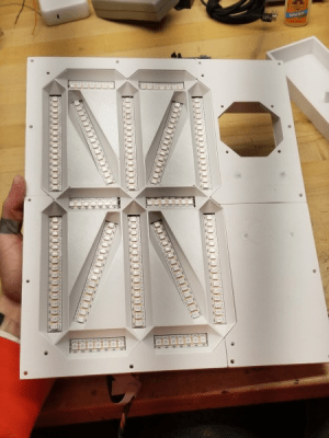
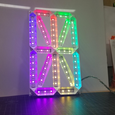
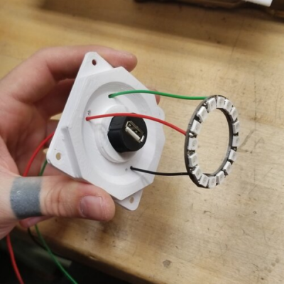
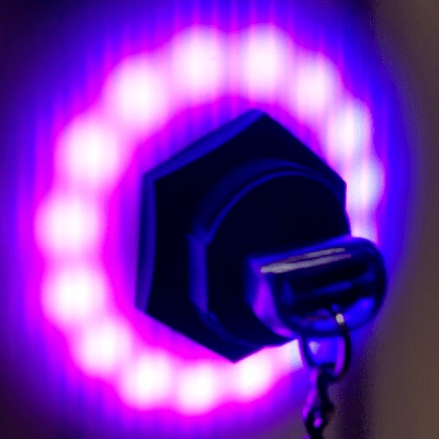
It took a while for [Mac] to finalize the plan for his design. He obtained a high resolution satellite image of the Iranian Natanz facility via the Sentinel Hub satellite imagery service. This was printed on a transparent vinyl and glued to a translucent poly-carbonate sheet. Behind the poly-carbonate layer, he built a large, single digit 16-segment display using WS2812 addressable LED strips, which would be used to display the Stuxnet code. A bulkhead USB socket was added over the centrifuge facility, with a ring of WS2812 LEDs surrounding the main complex. When a USB stick is plugged in, the Stuxnet code is displayed on the 16-segment display, one character at a time. At random intervals, the LED ring around the centrifuge building lights up spinning in a red color to indicate centrifuge failure.

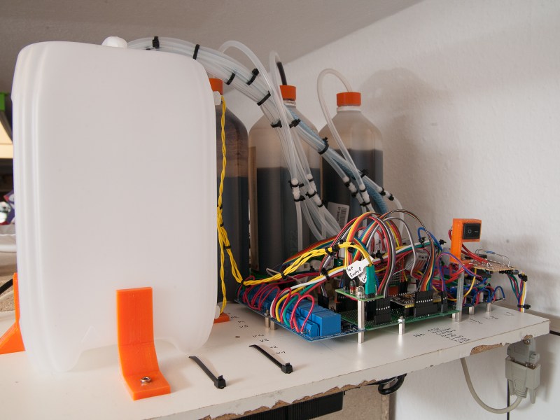
The 16-segment display was built on an aluminum base plate, with 3D printed baffles to hold the LED strips. To hold the rest of the electronics, he built a separate 3D printed frame which could be added to the main art frame. Since this was too large to be printed in one piece on the 3D printer, it was split in parts, which were then joined together using embedded metal stud reinforcement to hold the parts together. Quite a nice trick to make large, rigid parts.

An Adafruit Feather M0 micro-controller board, with micro SD-card slot was the brains of the project. To derive the 5 V logic data signal from the 3.3 V GPIO output of the Feather, [Mac] used two extra WS2812 LEDs as level shifters before sending the data to the LED strips. Driving all the LEDs required almost 20 W, so he powered it using USB-C, adding a power delivery negotiation board to derive the required juice.

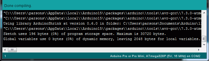
The Arduino code is straightforward. It reads the characters stored on the SD-card, and sends them sequentially to the 16-segment display. The circular ring around the USB bulkhead also lights up white, but at random intervals it turns red to simulate the speeding up of the centrifuges. Detecting when the USB stick gets plugged in is another nice hack that [Mac] figured out. When a USB stick is plugged in, the continuity between the shell (shield) and the GND terminal was used to trigger a GPIO input.

Cyber warfare is here to stay. We are already seeing increasing attacks on key infrastructure installations by state as well as non-state actors around the world. Stuxnet was one of the first in this growing category of malicious, weaponized code. Acknowledging its presence using such a physical representation can offer a reminder on how a few lines of software can wreak havoc just as much as any other physical weapon. Check out the brief project video after the break.

Honey, I Shrunk the Arduino Core

High-level programming languages do a great job of making a programmer’s job easier, but these languages often leave a lot of efficiency on the table as a compromise. While a common thought is to move into a lower-level language like assembly to improve on a program’s speed or memory use, there’s often a lot that can be done at the high level before resorting to such extremes. This, of course, is true of the Arduino platform as well, as [NerdRalph] demonstrates by shrinking the size of the Arduino core itself.

[NerdRalph] had noticed that the “blink” example program actually includes over 1 kB of extraneous code, and that more complicated programs include even more cruft. To combat this issue, he created ArduinoShrink, which seeks to make included libraries more modular and self-contained. It modifies the some of the default registers and counters to use less memory and improve speed, and is also designed to improve interrupt latency as well by changing when the Arduino would otherwise disable interrupts.

While there are some limits to ArduinoShrink, such as needing to know specifics about the pins at compile time, for anyone writing programs for Arduinos that are memory-intensive or need improvements in timing this could be a powerful new tool. If you’d prefer to go in the opposite direction to avoid ever having to learn C or assembly, though, you can always stick with running Python on your embedded devices.

Never Forget To Turn On The Cooker Hood Again

The cooker hood is a wonderful invention for removing excess fumes and steam from the kitchen. But like all electrically-powered devices, it only works when it is turned on. This was the problem facing [Peter], whose family are enthusiastic cooks who frequently forget to hit that switch. His solution? An automatic cooker hood switch that comes on when the cooker is in use, and stays on long enough afterwards to fully dissipate the fumes.

At its heart is a current transformer on the 3-phase stove power line, and we’re treated to a lesson in reading from these devices with an Arduino. They have a shunt resistor across which to produce a voltage, and their AC output is placed upon a reference DC voltage to supply the microcontroller pin. The impedance is quite high, so when the sensor had to be placed a distance from the microcontroller it necessitated an op-amp buffer. The readings then cause the Arduino to trigger a pair of relays to switch on or off the cooker hood. We can imagine that the family kitchen is thus a much pleasanter environment for it.

Cookers can also provide quite a hazard when they are left on. To that end, we’ve also featured a cooker alarm in the past.

Header image: Pbroks13, CC BY-SA 3.0.

He’s the Operator of His Pocket Arduino

The band Kraftwerk hit the music scene with its unique electronic sound in the 70s in Germany, opening the door for the electronic music revolution of the following decade. If you’re not familiar with the band, they often had songs with a technology theme as well, and thanks to modern microcontroller technology it’s possible to replicate the Kraftwerk sound with microcontrollers as [Steven] aka [Marquis de Geek] demonstrates in his melodic build.

While the music is played on a Stylophone and a Korg synthesizer, it is fed through five separate Arduinos, four of which have various synths and looping samplers installed on them (and presumably represent each of the four members of Kraftwerk). Samplers like this allow pieces of music to be repeated continuously once recorded, which means that [Steven] can play entire songs on his own. The fifth Arduino functions as a controller, handling MIDI and pattern sequencing over I2C, and everything is finally channeled through a homemade mixer.

[Marquis] also dressed in Kraftwerk-appropriate attire for the video demonstration below, which really sells the tribute to the famous and groundbreaking band. While it’s a great build in its own right and is a great recreation of the Kraftwerk sound, we can think of one more way to really put this project over the top — a Kraftwerk-inspired LED tie.

Hacker Driven to Build R/C Forza Controller

Generic video game console controllers have certainly gotten better and more ergonomic since the hard corners of the Atari joystick. As beautiful and engrossing as games have become, the controller is still the least engaging aspect. Why race your sweet fleet of whips with an ordinary controller when you could pretend they’re all R/C cars?

[Dave] found an affordable 4-channel R/C controller in the Bezos Barn and did just that. It took some modifications to make it work, like making a daughter board to turn the thumb grip input from a toggle button to a momentary and figuring out what to do with the three-way slider switch, but it looks like a blast to use.

The controller comes in a 6-channel version with two pots on the top. Both versions have the same enclosure and PCB, so [Dave] already had the placement molded out for him when he decided to install a pair of momentary buttons up there. These change roles based on the three-way slider position, which switches between race mode, menu mode, and extras mode.

We love the way [Dave] turned the original receiver into a USB dongle that emulates an Xbox 360 controller — he made a DIY Arduino Pro Micro with a male USB-A, stripped down the receiver board, and wired them together. There’s an entire separate blog post about that, and everything else you’d need to make your own R/C controller is on GitHub. Check out the demo and overview of the controls after the break.

[Dave] is no stranger to making game controllers — we featured his DJ Hero controller modified to play Spin Rhythm XD a few months ago.

Via r/duino

Son of Rothult

We are continuously inspired by our readers which is why we share what we love, and that inspiration flows both ways. [jetpilot305] connected a Rothult unit to the Arduino IDE in response to Ripping up a Rothult. Consider us flattered. There are several factors at play here. One, the Arduino banner covers a lot of programmable hardware, and it is a powerful tool in a hardware hacker’s belt. Two, someone saw a tool they wanted to control and made it happen. Three, it’s a piece of (minimal) security hardware, but who knows where that can scale. The secure is made accessible.

The Github upload instructions are illustrated, and you know we appreciate documentation. There are a couple of tables for the controller pins and header for your convenience. You will be compiling your sketch in Arduino’s IDE, but uploading through ST-Link across some wires you will have to solder. We are in advanced territory now, but keep this inspiration train going and drop us a tip to share something you make with this miniature deadbolt.

Locks and security are our bread and butter, so enjoy some physical key appreciation and digital lock love.

Bluepill Copies Code So You Don’t Have To

You really should learn to read Morse code. But if you can’t — or even if you can, and just want a break — you can always get a computer to do it. For example, [jmharvey1] has a decoder that runs on a cheap Bluepill dev board.

The device uses a touchscreen and a few common components. The whole thing cost about $16. You can see it at work along with a description of the project in the video below.

The code uses the Arduino-style setup for the Blue pill — something we’ve talked about before. As for the decoding method, the software employs the Goertzel algorithm which is akin to a single frequency Fourier transform. That is, while a full transform gives you information about the frequency component of a signal across a wide range, the Goertzel algorithm probes the signal for one or a small number of distinct frequencies.

The decoder table looks confusing at first until you realize that each “decode” value consists of a 1 as a start bit followed by a 1 for a dash and a zero for a dot. All bits to the left of the start bit don’t count. So an “E” codes as 02 hex — a start bit followed by a single zero or dot. A “C” is 1A hex (1 + -.-.). Once you find the matching code, you apply the same index to another table to look up the actual letter or string of letters.

If you buy a Bluepill to make one of these, you might as well get two and build something to send code, too.

Open-Source ARM Development Simplified

The ARM series of processors are an industry standard of sorts for a vast array of applications. Virtually anything requiring good power or heat management, or any embedded system which needs more computing power than an 8-bit microcontroller is a place where an ARM is likely found. While they do appear in various personal computers and laptops, [Pieter] felt that their documentation for embedded processors wasn’t quite as straightforward as it could be and created this development board which will hopefully help newbies to ARM learn the environment more easily.

Called the PX-HER0, it’s an ARM development board with an STM32 at its core and a small screen built in. The real work went in to the documentation for this board, though. Since it’s supposed to be a way to become more proficient in the platform, [Pieter] has gone through great links to make sure that all the hardware, software, and documentation are easily accessible. It also comes with the Command Line Interpreter (CLI) App which allows a user to operate the device in a Unix-like environment. The Arduino IDE is also available for use with some PX-HER0-specific examples.

[Pieter] has been around before, too. The CLI is based on work he did previously which gave an Arduino a Unix-like shell as well. Moving that to the STM32 is a useful tool to have for this board, and as a bonus everything is open source and available on his site including the hardware schematics and code.

Review: OSEPP STEM Kit 1, a Beginner’s All-in-One Board Found in the Discount Aisle

As the name implies, the OSEP STEM board is an embedded project board primarily aimed at education. You use jumper wires to connect components and a visual block coding language to make it go.

I have fond memories of kits from companies like Radio Shack that had dozens of parts on a board, with spring terminals to connect them with jumper wires. Advertised with clickbait titles like “200 in 1”, you’d get a book showing how to wire the parts to make a radio, or an alarm, or a light blinker, or whatever.

The STEM Kit 1 is sort of a modern arduino-powered version of these kits. The board hosts a stand-alone Arduino UNO clone (included with the kit) and also has a host of things you might want to hook to it. Things like the speakers and stepper motors have drivers on board so you can easily drive them from the arduino. You get a bunch of jumper wires to make the connections, too. Most things that need to be connected to something permanently (like ground) are prewired on the PCB. The other connections use a single pin. You can see this arrangement with the three rotary pots which have a single pin next to the label (“POT1”, etc.).

I’m a sucker for a sale, so when I saw a local store had OSEPP’s STEM board for about $30, I had to pick one up. The suggested price for these boards is $150, but most of the time I see them listed for about $100. At the deeply discounted price I couldn’t resist checking it out.

So does an embedded many-in-one project kit like this one live up to that legacy? I spent some time with the board. Bottom line, if you can find a deal on the price I think it’s worth it. At full price, perhaps not. Join me after the break as I walk through what the OSEPP has to offer.

What’s Onboard?

There are plenty of input and output devices:

  • 7 Push Buttons
  • Potentiometers (3 rotary and 1 slide)
  • Passive Infrared Sensor (PIR)
  • Light Sensor
  • Sound Sensor
  • LM35 Temperature Sensor
  • 10 LEDs (various colors)
  • Servo Motor
  • Stepper Motor
  • DC Motor
  • LCD Display
  • Buzzer
  • Speaker
  • RGB LED

In addition, the kit comes with an ultrasonic distance sensor in a little bracket that can connect to the stepper motor. That’s the only part that needs power and ground that isn’t already wired up.

Because the heart of the board is an Arduino UNO clone, you can do anything you like to program it. However, OSEPP touts their visual block diagram language that is basically Scratch. You can use it for free on most platforms and there is even a Web-based version although it can’t download code. It looks like Scratch or other block-oriented systems you’ve seen before.

I’m not usually fond of the visual block languages, but this one at least shows you the actual Arduino code it generates, so that isn’t bad. But you can still use any other method you like such as the standard IDE or PlatformIO.

You can see a video about the board, below.

The Good and the Bad

The board feels substantial and able to withstand a good bit of abuse. There’s a good range of components, and I like that the arduino is a real daughter board and not just built onto the PCB. Despite using the block language, I do like the tutorial booklet. It is very slick and has projects ranging from an IR doorbell to a mini piano. You can see a page below — very colorful and clear.

Of course, the suggested retail price of $150 is a bit offputting. You might think a breadboard with a handful of LEDs and other parts would be a much lower-cost option but just look around for arduino kits for beginners and you’ll find prices are all over the place. On the other hand, with a parts kit you would have to know how to wire up things like stepper motors or DC motors, so there is some value to having it already done for you. There’s also value in not having a bag of parts to misplace.

The jumper wires in the kit have pins on one side and sockets on the other. The pins go into the Arduino’s connector and the sockets go over pins on the components. These aren’t quite as reliable as a spring clip and not as versatile either.

In my mind the worst part of the kit design is that the pins are right next to each of the components. That’s good for understanding, but it makes a mess of wiring. For instance, there are ten LEDs, and connecting them all means stretching jumper wires to both edges of the board The jumpers aren’t very long either, so any complex project is going to have wires crisscrossing the sensors and LCD.

Granted, in this image I could have removed some of the wires from the bundles but that wouldn’t help that much, either. If you need to hook up more than a few of the available components you will have a mess. I would have put some sort of spring clip or even screw terminals and put them all on the top and bottom of the board with clear color-coded marking about where they connect. Then the wiring would all be out of the way. There are probably a few other ways they could have gone, and at this price, they could afford the few extra inches on the PCB.

There are a few other things that would have been nice touches to finish off this kit. I would have enjoyed a short chapter in the booklet about using the Arduino IDE directly so that people know it exists. And having even a small breadboard attached for your own exploration would make sense, but would then call for a different type of jumper wire.

Short Example Using the Distance Sensor

I wanted to do something with the board so I decided to play with the distance sensor and the servo. The distance sensor is a bit annoying both because you have to wire it all up and it has a tendency to fall off when you transport the board.

The demo (you can find it online) won’t win any originality prizes. The program moves the servo to scan from 0 to 180 degrees in 5 degree increments. It measures the distance of what’s in front of it. When it completes a scan, if it saw something close (you could adjust the sensitivity), it moves the sensor back to that position and waits 30 seconds. Otherwise, it keeps scanning.

Really, this is no different from any other Arduino program. That’s kind of the point. Despite the emphasis in the book on the point-and-click language, this is really just an Arduino.

In Summary

For the deep sale price I found, the board will work well for its intended audience of students or anyone starting out with Arduino or microcontrollers. Even a more advanced audience who just wants a way to hammer out a quick prototype might find it worth the $30 or $40 you can sometimes pay. But at full price, it is hard to imagine this makes sense because of the mess of wire routing and limited expansion options.