Posts with «microcontrollers» label

Review: OSEPP STEM Kit 1, a Beginner’s All-in-One Board Found in the Discount Aisle

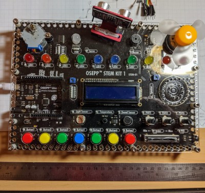
As the name implies, the OSEP STEM board is an embedded project board primarily aimed at education. You use jumper wires to connect components and a visual block coding language to make it go.

I have fond memories of kits from companies like Radio Shack that had dozens of parts on a board, with spring terminals to connect them with jumper wires. Advertised with clickbait titles like “200 in 1”, you’d get a book showing how to wire the parts to make a radio, or an alarm, or a light blinker, or whatever.

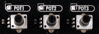
The STEM Kit 1 is sort of a modern arduino-powered version of these kits. The board hosts a stand-alone Arduino UNO clone (included with the kit) and also has a host of things you might want to hook to it. Things like the speakers and stepper motors have drivers on board so you can easily drive them from the arduino. You get a bunch of jumper wires to make the connections, too. Most things that need to be connected to something permanently (like ground) are prewired on the PCB. The other connections use a single pin. You can see this arrangement with the three rotary pots which have a single pin next to the label (“POT1”, etc.).
I’m a sucker for a sale, so when I saw a local store had OSEPP’s STEM board for about $30, I had to pick one up. The suggested price for these boards is $150, but most of the time I see them listed for about $100. At the deeply discounted price I couldn’t resist checking it out.

So does an embedded many-in-one project kit like this one live up to that legacy? I spent some time with the board. Bottom line, if you can find a deal on the price I think it’s worth it. At full price, perhaps not. Join me after the break as I walk through what the OSEPP has to offer.

What’s Onboard?

There are plenty of input and output devices:

  • 7 Push Buttons
  • Potentiometers (3 rotary and 1 slide)
  • Passive Infrared Sensor (PIR)
  • Light Sensor
  • Sound Sensor
  • LM35 Temperature Sensor
  • 10 LEDs (various colors)
  • Servo Motor
  • Stepper Motor
  • DC Motor
  • LCD Display
  • Buzzer
  • Speaker
  • RGB LED

In addition, the kit comes with an ultrasonic distance sensor in a little bracket that can connect to the stepper motor. That’s the only part that needs power and ground that isn’t already wired up.
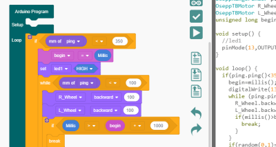
Because the heart of the board is an Arduino UNO clone, you can do anything you like to program it. However, OSEPP touts their visual block diagram language that is basically Scratch. You can use it for free on most platforms and there is even a Web-based version although it can’t download code. It looks like Scratch or other block-oriented systems you’ve seen before.

I’m not usually fond of the visual block languages, but this one at least shows you the actual Arduino code it generates, so that isn’t bad. But you can still use any other method you like such as the standard IDE or PlatformIO.

You can see a video about the board, below.

The Good and the Bad

The board feels substantial and able to withstand a good bit of abuse. There’s a good range of components, and I like that the arduino is a real daughter board and not just built onto the PCB. Despite using the block language, I do like the tutorial booklet. It is very slick and has projects ranging from an IR doorbell to a mini piano. You can see a page below — very colorful and clear.

Of course, the suggested retail price of $150 is a bit offputting. You might think a breadboard with a handful of LEDs and other parts would be a much lower-cost option but just look around for arduino kits for beginners and you’ll find prices are all over the place. On the other hand, with a parts kit you would have to know how to wire up things like stepper motors or DC motors, so there is some value to having it already done for you. There’s also value in not having a bag of parts to misplace.

The jumper wires in the kit have pins on one side and sockets on the other. The pins go into the Arduino’s connector and the sockets go over pins on the components. These aren’t quite as reliable as a spring clip and not as versatile either.

In my mind the worst part of the kit design is that the pins are right next to each of the components. That’s good for understanding, but it makes a mess of wiring. For instance, there are ten LEDs, and connecting them all means stretching jumper wires to both edges of the board The jumpers aren’t very long either, so any complex project is going to have wires crisscrossing the sensors and LCD.
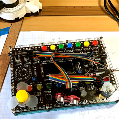
Granted, in this image I could have removed some of the wires from the bundles but that wouldn’t help that much, either. If you need to hook up more than a few of the available components you will have a mess. I would have put some sort of spring clip or even screw terminals and put them all on the top and bottom of the board with clear color-coded marking about where they connect. Then the wiring would all be out of the way. There are probably a few other ways they could have gone, and at this price, they could afford the few extra inches on the PCB.

There are a few other things that would have been nice touches to finish off this kit. I would have enjoyed a short chapter in the booklet about using the Arduino IDE directly so that people know it exists. And having even a small breadboard attached for your own exploration would make sense, but would then call for a different type of jumper wire.

Short Example Using the Distance Sensor

I wanted to do something with the board so I decided to play with the distance sensor and the servo. The distance sensor is a bit annoying both because you have to wire it all up and it has a tendency to fall off when you transport the board.

The demo (you can find it online) won’t win any originality prizes. The program moves the servo to scan from 0 to 180 degrees in 5 degree increments. It measures the distance of what’s in front of it. When it completes a scan, if it saw something close (you could adjust the sensitivity), it moves the sensor back to that position and waits 30 seconds. Otherwise, it keeps scanning.

Really, this is no different from any other Arduino program. That’s kind of the point. Despite the emphasis in the book on the point-and-click language, this is really just an Arduino.

In Summary

For the deep sale price I found, the board will work well for its intended audience of students or anyone starting out with Arduino or microcontrollers. Even a more advanced audience who just wants a way to hammer out a quick prototype might find it worth the $30 or $40 you can sometimes pay. But at full price, it is hard to imagine this makes sense because of the mess of wire routing and limited expansion options.

A Colorful Way To Play Chess On An ATmega328

We’ve all seen those chess computers that consist out of a physical playing field, and a built-in computer that would indicate where you should put its pieces while inputting the position of your pieces in some way. These systems are usually found in a dusty cardboard box in a back room’s closet, as playing like this is fairly cumbersome, and a lot depends on the built-in chess computer.

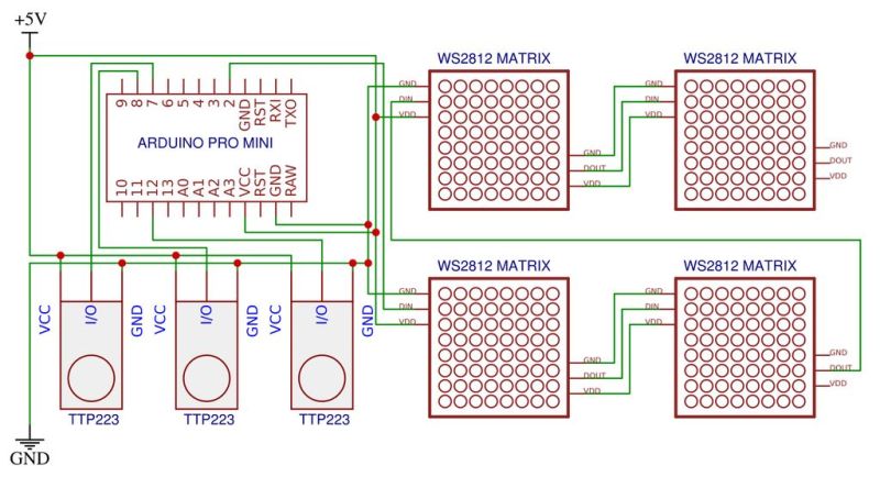
This take by [andrei.erdei] on this decades-old concept involves an ATmega328p-based Arduino Pro Mini board, a nice wooden frame, and 4 WS2812-based 65×65 mm RGB 8×8 LED matrices, as well as some TTP223 touch sensors that allow one to control the on-board cursor. This is the sole form of input: using the UP and RIGHT buttons to select the piece to move, confirm with OK, then move to the new position. The chess program will then calculate its next position and indicate it on the LED matrix.

Using physical chess pieces isn’t required either: each 4×4 grid uses a special pattern that indicates the piece that occupies it.  This makes it highly portable, but perhaps not as fun as using physical pieces. It also kills the sheer joy of building up that collection of enemy pieces when you’ve hit that winning streak. You can look at the embedded gameplay video after the break and judge for yourself.

At the core of the chess program is [H.G. Muller]’s micro-Max project. Originally ported to the Arduino Uno, this program outputs the game to the serial port. After tweaking it to use the LED matrix instead, [andrei.erdei] was then faced with the lack of memory on the board for the most common LED libraries. In the end, the FAB_LED library managed to perform the task with less memory, allowing it and the rest of the program to fit comfortably into the glorious 2 kB of SRAM that the ATmega328p provides.

Classic 8-bit chess engines are marvels of software engineering. Ever wonder how they stack up against modern chess software? Check out this article!

New Teensy 4.0 Blows Away Benchmarks, Implements Self-Recovery, Returns to Smaller Form

Paul Stoffregen did it again: the Teensy 4.0 has been released. The latest in the Teensy microcontroller development board line, the 4.0 returns to the smaller form-factor last seen with the 3.2, as opposed to the larger 3.5 and 3.6 boards.

Don’t let the smaller size fool you; the 4.0 is based on an ARM Cortex M7 running at 600 MHz (!), the fastest microcontroller you can get in 2019, and testing on real-world examples shows it executing code more than five times faster than the Teensy 3.6, and fifteen times faster than the Teensy 3.2. Of course, the new board is also packed with periperals, including two 480 Mbps USB ports, 3 digital audio interfaces, 3 CAN busses, and multiple SPI/I2C/serial interfaces backed with integrated FIFOs. Programming? Easy: there’s an add-on to the Arduino IDE called Teensyduino that “just works”. And it rings up at an MSRP of just $19.95; a welcomed price point, but not unexpected for a microcontroller breakout board.

The board launches today, but I had a chance to test drive a couple of them in one of the East Coast Hackaday labs over the past few days. So, let’s have a closer look.

First Impressions

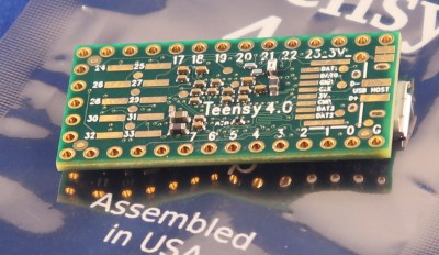
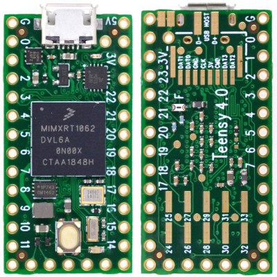
The board looks superficially similar to the older 3.2, at least from the top. There’s the usual dual row of pin headers you can plug into a breadboard, a micro-USB connector, and reset button. A new red LED near the USB connector gives you some status information, while the traditional “Arduino LED” is orange. Flip the board over, and you start to see some of the extra power this board wields. Besides ten more GPIO pins, there are pads for an SD card interface using 4-bit SDIO, and D+ and D- lines for the second 480 Mbps USB interface. The unmarked round pads are test points used in manufacturing and are no-connects from the end-user’s perspective.

Teensy 3.2 Everything Killer?

When doing hardware reviews it’s crucial to choose the right comparison hardware. I think the best comparison in this case is between the two boards that share the same form factor; the Teensy 4.0 and the 3.2. I’ve chosen not to make the comparison with the Teensy 3.5 and 3.6, which are priced a little higher, in a larger form factor, and have SD card slots soldered on.

Incredibly, the Teensy 4.0 is priced at $19.95, as opposed to the $19.80 Teensy 3.2. What does that extra fifteen cents buy? First, there’s performance. The 4.0’s 600 MHz clock vs the 72 MHz on the 3.2 doesn’t tell the whole story. The Cortex M7 on the 4.0 is a dual-issue superscalar processor capable of executing up to two 32-bit instructions per clock cycle; initial tests showed this happening between 40-50% of the time on Arduino-compiled code. Additionally, the Cortex-M7 is the first ARM microcontroller with branch prediction. While on the Cortex M4, a branch always takes 3 clock cycles, after a few passes through a loop, for instance, the Cortex M7 can begin executing correctly-predicted branches in a single clock. This is technology originally pioneered in supercomputers that you can use in your next Halloween costume.
Then, there’s floating-point. Veteran embedded programmers may have a bias against floating-point code, and with good reason. Without native floating-point instructions, these operations must be emulated, and run very slowly. The same thing happens with double-precision operations on a processor which only supports single-precision instructions. While Cortex-M4 processors support single-precision floating-point, the Cortex-M7’s include native double-precision instructions, so if you need the extra precision afforded by doubles, you’re not going to take a huge performance hit: basically, doubles seem to execute in only twice as many cycles as floats.

The Cortex-M7 on this board also supports tightly-coupled memory (TCM), which provides fast access like a cache, but without the non-determinism that can complicate hard real-time applications — one of the problems with other high-power microcontrollers. The 64-bit ITCM bus can fetch 64-bits, while two dedicated 32-bit buses (DTCM) can fetch up to two instructions from the TCM each cycle – these buses are separate from the main AXI bus used to communicate with other memory and peripherals. The Teensyduino environment automatically allocates code and statically allocated memory into the DTCM area, which can be up to 512K in size, although you can override the default behavior with some command-line switches. Memory that isn’t accessed by the tightly-coupled buses is optimized for access by the peripherals using DMA.

Spec Sheet

Despite its size, there’s a lot to this board and the chip it carries, so here’s condensed spec list:

  • ARM Cortex-M7 at 600 MHz
  • 1024K RAM (512K is tightly coupled)
  • 2048K Flash (64K reserved for recovery & EEPROM emulation)
  • 2 USB ports, both 480 MBit/sec
  • 3 CAN Bus (1 with CAN FD)
  • 2 I2S Digital Audio
  • 1 S/PDIF Digital Audio
  • 1 SDIO (4 bit) native SD
  • 3 SPI, all with 16 word FIFO
  • 3 I2C, all with 4 byte FIFO
  • 7 Serial, all with 4 byte FIFO
  • 32 general purpose DMA channels
  • 31 PWM pins
  • 40 digital pins, all interrupt capable
  • 14 analog pins, 2 ADCs on chip
  • Cryptographic Acceleration
  • Random Number Generator
  • RTC for date/time
  • Programmable FlexIO
  • Pixel Processing Pipeline
  • Peripheral cross triggering
  • Power On/Off management

The board consumes around 100 mA with a 600 MHz clock. Although I didn’t try it myself with the evaluation boards I have here, Paul notes that it can be overclocked for a performance boost. It also supports dynamic clock scaling: the instruction clock speed is decoupled from the peripherals, so that baud rates, audio sample rates, and timing functions continue to function properly if you change the CPU speed.

For the ultimate in power savings, you can shut the board off by adding a pushbutton to the On/Off pin. Pressing the button for more than five seconds disables the 3.3 V supply; a subsequent brief press will turn it back on. This doesn’t affect the real-time-clock (RTC) functionality, however: connecting a coin cell to the VBAT terminal will keep the time and date counter going.

Hands-On Benchmarks

Higher is better
Board CoreMark
Teensy 4.0 2313.57
Teensy 3.6 440.72
Sparkfun ESP32 Thing 351.33
Teensy 3.5 265.50
Teensy 3.2 218.26
Metro M4 Grand Central 214.85
Arduino Due 94.95
Arduino Zero 56.86
Arduino Mega 7.03

To see how fast this thing really is, Paul ported the CoreMark embedded-processor benchmark to the Arduino environment. (Note that CoreMark seems to be a registered trademark of the Embedded Microprocessor Benchmark Consortium (EEMBC)). This synthetic benchmark tests performance managing linked lists, doing matrix multiplies, and executing state machine code. He reports the following scores for a number of boards (larger numbers are better).

I was able to verify the Teensy 4.0 and 3.2 numbers; my 3.6 must have sprouted legs and walked off somewhere, and I didn’t have any of the other boards handy for testing. Using my numbers (nearly identical to those above), the 4.0 is around ten times as fast as the 3.2.

Since the CoreMark code is a “synthetic” benchmark, Paul wanted to test the new board in a more realistic scenario. In another GitHub repo, he has some code to do an RSA signature with a 2048-bit key. This is a processor-intensive operation, believe me — I had to implement it once in Lua (don’t ask!). Here are the scores for the same boards (lower numbers are better).

Lower is better
Board Seconds
Teensy 4.0 0.085
Teensy 3.6 0.474
Sparkfun ESP32 Thing 0.518
Metro M4 Grand Central 0.840
Teensy 3.5 0.909
Teensy 3.2 1.325
Arduino Due 1.901
Arduino Zero 9.638

Again, I was able to verify the numbers for the Teensy 3.2 and 4.0 boards. In this case, the 4.0 is around fifteen times as fast as the 3.2.

If you have any of these, or other Arduino-compatible boards lying around, clone one or both of these repos, open the respective *.ino file from either one, and test them out. Feel free to report results in the comments below.

15 Seconds to Sanity

One of the new features of the Teensy 4.0 is the automatic recovery process, which restores the board to a known good state without the need for a PC connection. If you press and hold the reset button for 15 seconds, the red LED will flash to indicate you’ve entered restore mode. Once you release the button, the red LED will illuminate while the flash memory is erased and re-written with the traditional Arduino “blink” program. Once the re-write is complete, the blink program is run and the orange LED begins blinking, just like on every Arduino-compatible for the past decade and a half. It’s DFU mode without the need for host computer or known-working binary. These used to be key components for hardware-based restore and now they’re part of the board itself.

Why would you want to do this? In a nutshell, because USB itself is a train-wreck. On top of an insanely sprawling and complex protocol, there are charge-only cables sans data pins lurking in your junk box, operating system bugs waiting to trip you up (looking at you, Windows 7), and a whole host of other issues that cause serious head-scratching when things stop working. This can be especially confusing with native-USB boards like the Teensy 4.0; while the built-in USB functionality is amazingly powerful, and can be used in a wide variety of ways, when something stops working, you’re not always sure how to get back on track. Now, you are – just press the button.

What Can You Do with a 600 MHz Microcontroller?

Paul envisions this Teensy 4.0 being used for polyphonic audio synthesis, running moderately complex machine learning algorithms, and real-time audio analysis. In many cases, the first level of processing on data-intensive input devices can now be moved from a host computer to the external microcontroller, narrowing the bandwidth required to the host system. And for projects driving a display, the built-in pixel processing pipeline can also accelerate graphics operations, offloading this work from the CPU.

There will be some fraction of hackers that will still wonder why we need a 600 MHz microcontroller; another fraction will have already needed it yesterday. In between, most users will take some time to figure out what doors this opens up. The reality is that our tools constrain not only our current designs, but also, to some extent, our imagination. A 15x performance improvement over the current tiny development board you may be using could enable some new and exciting applications, and you, dear reader, are the one who makes them happen. So, drive home a different way from work tonight, sleep on the sofa instead of the bed, or use whatever other tricks you have to shock your brain into creativity and figure out what you could really do with this thing. It’s a lot more than you can do with a 555. For that matter, it’s a lot more than most computers could do in the 90s.

An Epic Tale of Thermistors: Tricks for Much Better Temperature Sensing

For years [Edward] has been building professional grade underwater sensing nodes at prices approachable for an interested individual without a government grant. An important component of these is temperature, and he has been on a quest to get the highest accuracy temperature readings from whatever parts hit that sweet optimum between cost and complexity. First there were traditional temperature sensor ICs, but after deploying numerous nodes [Edward] was running into the limit of their accuracy. Could he use clever code and circuitry to get better results? The short answer is yes, but the long answer is a many part series of posts starting in 2016 detailing [Edward]’s exploration to get there.

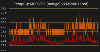
Orange is 12 bits, red is 24

The first step is a thermistor, a conceptually simple device: resistance varies with temperature (seriously, how much more simple can a sensor get?). You can measure them by tapping the center of a voltage divider the same way you’d measure any other resistance, but [Edward] had discarded this idea because the naive approach combined with his Arduino’s 10 bit ADC yielded resolution too poor to be worthwhile for his needs. But by using the right analog reference voltage and adjusting the voltage divider he could get a 20x improvement in resolution, down to 0.05°C in the relevant temperature range. This and more is the subject of the first post.

What comes next? Oversampling. Apparently fueled by a project featured on Hackaday back in 2015 [Edward] embarked on a journey to applying it to his thermistor problem. To quote [Edward] directly, to get “n extra bits of resolution, you need to read the ADC four to the power of n times”. Three bits gives about an order of magnitude better resolution. This effectively lets you resolve signals smaller than a single sample but only if there is some jitter in the signal you’re measuring. Reading the same analog line with no perturbation gives no benefit. The rest of the post deals with the process of artificially perturbing the signal, which turns out to be significantly complex, but the result is roughly 16 bit accuracy from a 10 bit ADC!

What’s the upside? High quality sensor readings from a few passives and a cheap Arduino. If that’s your jam check out this excellent series when designing your next sensing project!

Blisteringly Fast Machine Learning On An Arduino Uno

Even though machine learning AKA ‘deep learning’ / ‘artificial intelligence’ has been around for several decades now, it’s only recently that computing power has become fast enough to do anything useful with the science.

However, to fully understand how a neural network (NN) works, [Dimitris Tassopoulos] has stripped the concept down to pretty much the simplest example possible – a 3 input, 1 output network – and run inference on a number of MCUs, including the humble Arduino Uno. Miraculously, the Uno processed the network in an impressively fast prediction time of 114.4 μsec!

Whilst we did not test the code on an MCU, we just happened to have Jupyter Notebook installed so ran the same code on a Raspberry Pi directly from [Dimitris’s] bitbucket repo.

He explains in the project pages that now that the hype about AI has died down a bit that it’s the right time for engineers to get into the nitty-gritty of the theory and start using some of the ‘tools’ such as Keras, which have now matured into something fairly useful.

In part 2 of the project, we get to see the guts of a more complicated NN with 3-inputs, a hidden layer with 32 nodes and 1-output, which runs on an Uno at a much slower speed of 5600 μsec.

This exploration of ML in the embedded world is NOT ‘high level’ research stuff that tends to be inaccessible and hard to understand. We have covered Machine Learning On Tiny Platforms Like Raspberry Pi And Arduino before, but not with such an easy and thoroughly practical example.

Play Tetris on a Transistor Tester, Because Why Not?

[Robson] had been using the same multimeter since he was 15. It wasn’t a typical multimeter, either. He had programmed it to also play the Google Chrome jumping dinosaur game, and also used it as a badge at various conferences. But with all that abuse, the ribbon cable broke and he set about on other projects. Like this transistor tester that was just asking to have Tetris programmed onto its tiny screen.

The transistor tester is a GM328A made for various transistor testing applications, but is also an LCR meter. [Robson]’s old meter didn’t even test for capacitance but he was able to get many years of use out of that one, so this device should serve him even better. Once it was delivered he set about adding more features, namely Tetris. It’s based on an ATmega chip, which quite easy to work with (it’s the same chip as you’ll find in the Arduino Uno but [Robson’s] gone the Makefile route instead of spinning up that IDE). Not only did he add more features, but he also found a mistake in the frequency counter circuitry that he fixed on his own through the course of the project.

If you’ve always thought that the lack of games on your multimeter was a total deal breaker, this project is worth a read. Even if you just have a random device lying around that happens to be based on an ATmega chip of some sort, this is a good primer of getting that device to do other things as well. This situation is a fairly common one to be in, too.

An Arduino From The Distant Past

Arduinos are a handy tool to have around. They’re versatile, cheap, easy to program, and have a ton of software libraries to build on. They’ve only been around for about a decade and a half though, so if you were living in 1989 and wanted to program a microcontroller you’d probably be stuck with an 8-bit microprocessor with no built-in peripherals to help, reading from a physical book about registers and timing, and probably trying to get a broken ribbon cable to behave so it would actually power up. If you want a less frustrating alternate history to live in, though, check out the latest project from [Marek].

He discovered some 6502 chips (Polish language, Google Translate link) that a Chinese manufacturer was selling, but didn’t really trust that they were legitimate. On a lark he ordered some and upon testing them he found out that they were real 6502s. Building an 8-bit computer is something he’d like to do, but in the meantime he decided to do a project using one of these chips as a general-purpose microcontroller similar to a modern Arduino. The project has similar specs as an Arduino too, including 8kB of RAM memory, 8kB of I/O address space, and various EPROM capabilities. [Marek] went on to build a shield board for it as well, for easy access to some switches and LEDs. It’s a great build that anyone interested in microcontrollers should check out.

Keep in mind that an ATtiny45 has 8 bits like the 6502 but only costs around $1 USD, whereas a 6502 would have cost around $200 in today’s dollars. It’s really only in modern times that we can appreciate the 6502 as a cheap 8-bit microcontroller for that reason alone, but we can also appreciate how it ushered in a computer revolution since competing Intel and Motorola chips cost around six times more before it showed up. They became so popular in fact that people still regularly use them to build retrocomputers of all kinds.

Arduino Gets a Command Line Interface

When using an Arduino, at least once you’ve made it past blinking LEDs, you might start making use of the serial connection to send and receive information from the microcontroller. Communicating with the board while it’s interacting with its environment is a crucial way to get information in real-time. Usually, that’s as far as it goes, but [Pieter] wanted to take it a step farther than that with his command line interpreter (CLI) for the Arduino.

The CLI allows the user to run Unix-like commands directly on the Arduino. This means control of GPIO and the rest of the features of the microcontroller via command line. The CLI communicates between the microcontroller and the ANSI/VT100 terminal emulator of your choosing on your computer, enabling a wealth of new methods of interacting with an Arduino.

The CLI requires a hex file to be loaded onto the Arduino that you can find at a separate site, also maintained by [Pieter]. Once that’s running, you can get all of that sweet command line goodness out of your Arduino. [Pieter] also has some examples on his project page, as well as the complete how-to to get this all set up and running. There’s a lot going on in the command line world, in Linux as well as windows. So there’s plenty to explore there as well.

Hack a Day 11 Nov 03:00
arduino  cli  command line  gpio  i2c  microcontrollers  serial  shell  unix  uno  

Weather Station Is A Tutorial in Low Power Design

Building your own weather station is a fun project in itself, but building it to be self-sufficient and off-grid adds another set of challenges to the mix. You’ll need a battery and a solar panel to power the station, which means adding at least a regulator and charge controller to your build. If the panel and battery are small, you’ll also need to make some power-saving tweaks to the code as well. (Google Translate from Italian) The tricks that [Danilo Larizza] uses in his build are useful for more than just weather stations though, they’ll be perfect for anyone trying to optimize their off-grid projects for battery and solar panel size.

When it comes to power conservation, the low-hanging fruit is plucked first. [Danilo] set the measurement intervals to as long as possible and put the microcontroller (a NodeMCU) to sleep in between. Removing the power from the sensors when the microcontroller was asleep was another easy step, but the device was still crashing overnight. Then he turned to a hardware solution and added a more efficient battery charger to the setup, which saved even more power. This is all the more impressive because the station communicates via WiFi which is notoriously difficult to run in low-power applications.

Besides the low power optimizations, the weather station itself is interesting for its relative simplicity. It could be built with things most of us have knocking around. Best of all, [Danilo] published the source code on his site, so most of the hard work has been done already. If you’re thinking he seems a little familiar, it’s because we’ve featured some of his projects before, like his cheap WiFi extender antenna and his homemade hybrid tube amplifier.

Want to Learn Ethernet? Write Your Own Darn AVR Bootloader!

There’s a school of thought that says that to fully understand something, you need to build it yourself. OK, we’re not sure it’s really a school of thought, but that describes a heck of a lot of projects around these parts.

[Tim] aka [mitxela] wrote kiloboot partly because he wanted an Ethernet-capable Trivial File Transfer Protocol (TFTP) bootloader for an ATMega-powered project, and partly because he wanted to understand the Internet. See, if you’re writing a bootloader, you’ve got a limited amount of space and no device drivers or libraries of any kind to fall back on, so you’re going to learn your topic of choice the hard way.

[Tim]’s writeup of the odyssey of cramming so much into 1,000 bytes of code is fantastic. While explaining the Internet takes significantly more space than the Ethernet-capable bootloader itself, we’d wager that you’ll enjoy the compressed overview of UDP, IP, TFTP, and AVR bootloader wizardry as much as we did. And yes, at the end of the day, you’ve also got an Internet-flashable Arduino, which is just what the doctor ordered if you’re building a simple wired IoT device and you get tired of running down to the basement to upload new firmware.

Oh, and in case you hadn’t noticed, cramming an Ethernet bootloader into 1 kB is amazing.

Speaking of bootloaders, if you’re building an I2C slave device out of an ATtiny85¸ you’ll want to check out this bootloader that runs on the tiny chip.