Posts with «hardware» label

Multi-switch Useless Box Is Useless In Multiple Ways

We’ve probably all seen (and built) a useless box, in which you flip a switch that activates a servo that pops out a finger and flips the switch off. [Coffeman500] decided to take this a step further by building a useless box with multiple switches. Flip one, the finger pops out to flip it back. Flip several switches, and the finger pops out and flips each back in turn.

It’s a smart build that [coffeeman500] says is his first electronics build. The compulsively switching brain of this is an ATmega328 driving an A4988 stepper motor driver, with one stepper moving the finger mechanism and the other moving the finger along a rail to reach each switch in turn. [Coffeeman500] has released the complete plans for this wonderful waste of time, including 3D models for the box and mechanism, plus the code. Redditors are already planning bigger and more useless designs with more switches, a pursuit that we fully support.

Via [Reddit]

Hack a Day 18 Aug 06:00

H2gO Keeps Us from Drying Out

The scientific community cannot always agree on how much water a person needs in a day, and since we are not Fremen, we should give it more thought than we do. For many people, remembering to take a sip now and then is all we need and the H2gO is built to remind [Angeliki Beyko] when to reach for the water bottle. A kitchen timer would probably get the job done, but we can assure you, that is not how we do things around here.

A cast silicone droplet lights up to show how much water you have drunk and pressing the center of the device means you have taken a drink. Under the hood, you find a twelve-node NeoPixel ring, a twelve millimeter momentary switch, and an Arduino Pro Mini holding it all together. A GitHub repo is linked in the article where you can find Arduino code, the droplet model, and links to all the parts. I do not think we will need a device to remind us when to use the bathroom after all this water.

Another intrepid hacker seeks to measure a person’s intake while another measures output.

Held Captive by Arduino and Multiple RFID Readers

If you’re the kind of person who has friends, and/or leaves the confines of the basement from time to time, we hear that these “Escape Rooms” are all the rage. Basically you get locked into a room with a couple other people and have to solve various problems and puzzles until you’ve finally made enough progress that they let you out. Which actually sounds a lot like the working conditions here at Hackaday HQ, except they occasionally slip some pizza rolls under the door for us which is nice.

Whichever side you find yourself on in one of these lighthearted hostage situations, knowledge of this multi-tag RFID lock created by [Annaane] may come in handy. By connecting multiple MFRC522 RFID readers to an Arduino Uno, she’s come up with a method of triggering a device (like an electronic door lock) only when the appropriate combination of RFID tags have been arranged. With a little imagination, this allows for some very complex puzzle scenarios which are sure to keep your prisoners enthralled until you can lower the lotion down to them.

Her code allows you to configure the type and number of RFID cards required to trigger one of the Arduino’s digital pins, which usually would be connected to a relay to fire off whatever device you want. The Arduino sketch is also setup to give “hints” to the player by way of a status LED: fast blinking let’s you know the tag scanned is wrong, and slow blinking means you don’t have enough scanned in yet.

The video after the break shows some highlights of the build, as well as a quick demonstration of how both the RFID “combination” and manual override can be used to trigger the attached relay.

Hackers do love RFID. Using them for physical access control is a fairly common project around these parts, and we’ve even seen similar setups for the digital realm.

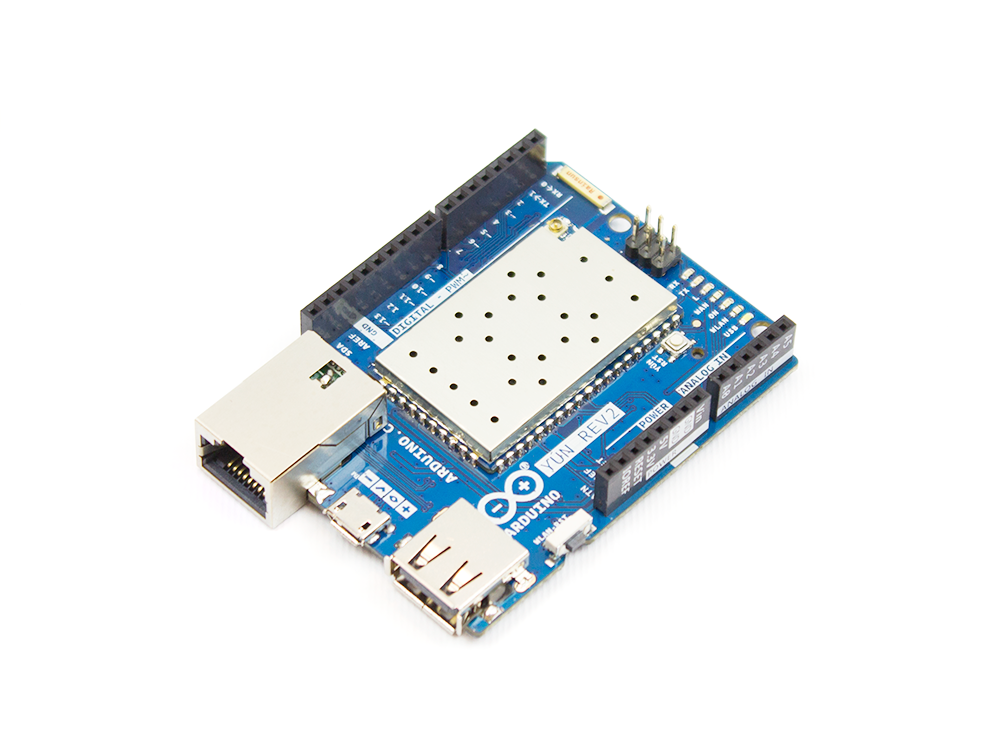
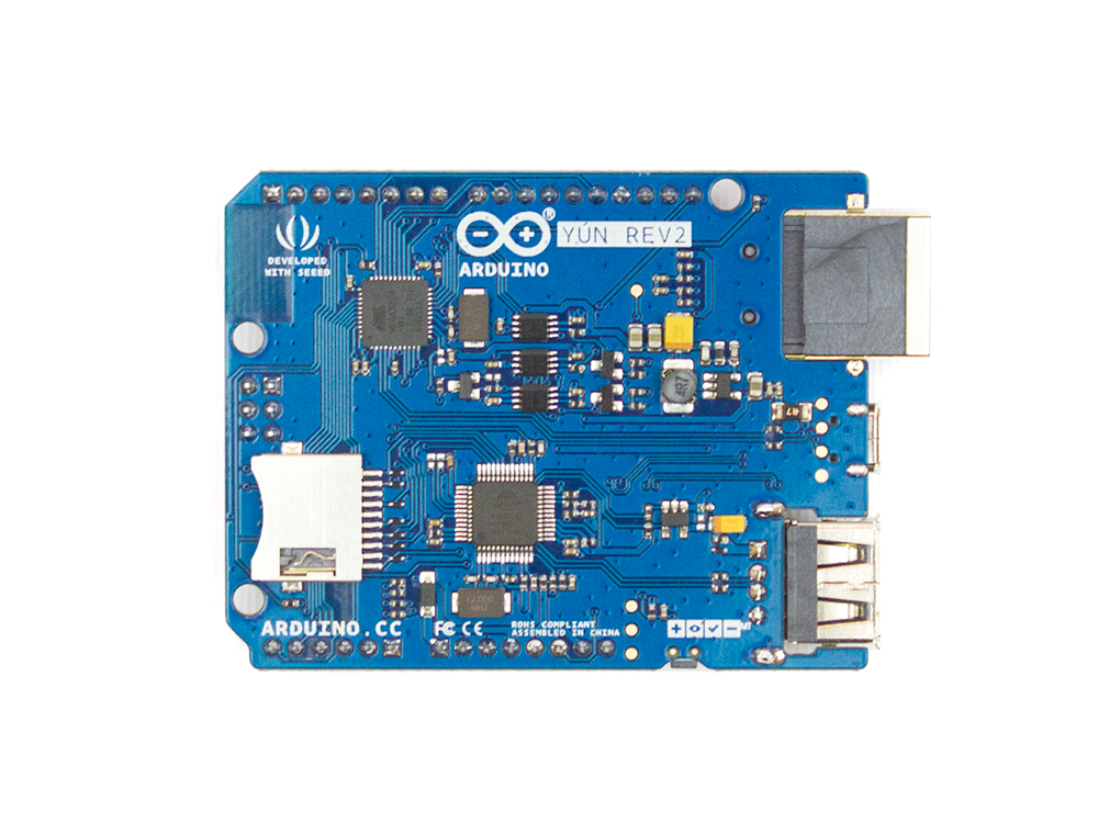
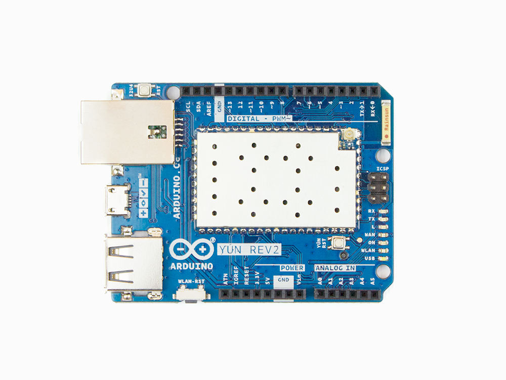
Arduino Yùn Rev.2 is here!

Since its launch in 2013, the Yùn–a small Linux machine and a microcontroller in a small Arduino form factor–found its way into hundreds of thousands of projects and professional applications. Last year, we decided that it was time for a refresh and began working hard to develop a true open-source design, with more compelling features and better overall software support.

The new board, which is expected to hit the market in the second half of April, will include enhanced functionality and compatibility with its predecessor.

Why a New Yùn

The Yùn enjoyed tremendous success; however, it ended up being affected by the internal issues we dealt with over the past couple of years and support has been quite intermittent.

For example, the board was never really an open-source product and the software had some challenges that we wanted to fix, especially from a security point of view.

What’s New in Rev.2

Hardware:  

  • Much better, more robust power supply
  • New Ethernet connector with a clever mounting solution that enables the use of all possible shields with no risk for accidental short circuits
  • Horizontal USB connector to save vertical space
  • Improved USB hub

Software: 

  • Software stack updated to OpenWRT latest version, including all patches
  • SSL support on the bridge Arduino / Linux bridge

Yùn Rev.2 is scheduled to begin shipping in April. Until then, you can stay up-to-date by clicking “NOTIFY ME” on our store

Circuit Bent Casio SK-1 gets an Arduino Brain

The Casio SK-1 keyboard is fairly well-known in the “circuit bending” scene, where its simple internals lend themselves to modifications and tweaks to adjust the device’s output in all sorts of interesting ways. But creating music via circuit bending the SK-1 can be tedious, as it boils down to fiddling with the internals blindly until it sounds cool. [Nick Price] wanted to do something a bit more scientific, and decided to try replacing his SK-1’s ROM with an Arduino so he could take complete control it.

Replacing the ROM chip with header pins.

That’s the idea, anyway. Right now he’s gotten as far as dumping the ROM and getting the Arduino hooked up in place of it. Unfortunately the resulting sound conjures up mental images of a 56K modem being cooked in a microwave. Clearly [Nick] still has some work ahead of him.

For now though, the progress is fascinating enough. He was able to pull the original NEC 23C256 chip out of the keyboard and read its contents using an Arduino and some code he cooked up, and he’s even put the dump online for any other SK-1 hackers out there. He then wrote some new code for the Arduino to spit data from the ROM dump back to the keyboard when requested. In theory, it should sound the same as before, but with the added ability to “forge” the data going back to the keyboard to make new sounds.

The result is what you hear in the video linked after the break. Not exactly what [Nick] had in mind. After some snooping with the logic analyzer, he believes the issue is that the Arduino can’t respond as fast as the original NEC chip did. He’s now got an NVRAM chip on order to replace the original NEC chip; the idea is that he can still use the Arduino to reprogram the NVRAM chip when he wants to play around with the sound.

We’ve covered some pretty fancy circuit bent instruments here in the past, but if you’re looking for something a bit easier to get your feet wet we ran a start-to-finish guide back in the Ye Olden Days of 2011 which should be helpful.

I’ll Have a Beer With a Compliment Chaser

[Andrew MacPherson] found out that compliments, even insincere ones, make the recipients feel better. So, he put together a thermal printer and a hilariously large button with an Arduino and created a machine that prints compliments. And where best to put a machine that prints out compliments? The local bar, where else?

An Arduino Nano clone runs the show connected to a thermal printer. The Nano clone didn’t like the 9 volt power supply, so a buck converter was used to reduce the voltage down to 5 volts for the Nano, while the printer gets the full power. During initial trials, the printer was very slow to print and it took [Andrew] a while to adjust the parameters – after tweaking the speed as well as the heating time, he was able to get the printer working without burning the paper or taking forever to print.

Once the machine was working, it was time to add a button. A large, light-up button was connected and glued to the side of the printer. More glue was used (after some “modifications” to the printer chassis) to secure a barrel connector for the power adapter.

[Andrew] decided that since he’s down at his favorite bar quite a lot, he’d set it up there. The customers could push the button and receive a compliment while drowning their sorrows. He got a friend of his who’s a copywriter to come up with some nicely written compliments to print out. The printer was such a hit that the bartender sent [Andrew] a message on Facebook saying so. If you have a thermal printer lying around, you can use this tutorial to connect it to the internet, or, if you don’t have one, you can build your own.

Final Project for Better Sleep

It’s that time of year again, and students around the world are scrambling (or have already scrambled) to finish their final projects for the semester. And, while studying for finals prevents many from sleeping an adequate amount, [Julia] and [Nick] are seeking to maximize “what little sleep the [Electrical and Computer Engineering] major allows” them by using their final project to measure sleep quality.

To produce a metric for sleep quality, [Julia] and [Nick] set out to measure various sleep-related activities, specifically heart rate, motion and breath frequency. During the night, an Arduino Nano mounted to a glove collects data from the various sensors mounted to the user, all the while beaming the data to a stationary PIC for analysis and storage. When the user awakes, they can view their sleep report on a TFT display at the PIC base station. Ideally, users would use this data to test different habits in order to get the best nights sleep possible.

Interestingly, the group chose to implement their own heart rate sensor. With an IR transmitter, IR phototransistor and an OP amp, the group illuminates user’s fingers and measure reflection to detect heartbeats. This works because the amount of IR reflected from the user’s finger changes with blood pressure and blood oxygen level, which also happen to change when the heart is beating. There were some bumps along the road when it came to the heartbeat sensor (the need to use a finger instead of the wrist forced them to use a glove instead of a wristband), but we think it’s super cool and totally worth it. In addition to heart rate, motion is measured by an accelerometer and breath is measured by a flex sensor wrapped around the user’s chest.

With all of their data beamed back by a pair of nRF24L01s, the PIC computes the sleep “chaos” which is exactly what it sounds like: it describes just how chaotic the user slept by looking for acyclic and sudden movement. Using this metric, combined with information from breathing and heart rate, the PIC computes a percentage for good sleep where 100% is a great night and 0% means you might have been just as well off pulling an all-nighter. And, to top it all off, the PIC saves your data to an SD card for easy after-the-fact review.

The commented code that powers the project can be found here along with a parts list in their project write-up.

This device assumes that sleeping is the issue, but if waking up if your problem, we’ve already got you covered, aggressive alarm clock style. For those already on top of their sleep, you might want some help with lucid dreaming.

Video of the project explained by [Julia] and [Nick] after the break.

Thanks to [Nick] for sending this in!


Filed under: hardware

Laser Cutter Alignment Mod Skips Beam Combiner

A lot of the DIY laser engravers and cutters we cover here on Hackaday are made with laser diodes salvaged from Blu-ray drives and projectors, which are visible lasers in the 400 – 450nm range (appearing as violet or blue). Unfortunately there is an upper limit in terms of power on visible diode lasers, most builds max out at 5W or so. If you need more power than that, you’ll likely find yourself looking at gas laser cutters like the K40. While the K40 is a great starting point if you’re looking to get into “real” lasers, it’s a very different beast from the homebrew builds using visible lasers.

With a gas laser the beam itself is invisible, making it much more difficult to align or do test runs. One solution is to add a visible laser to the K40 which can be used to verify alignment, but making sure it’s traveling down the same path as the primary laser usually requires an expensive beam combiner. Looking to avoid this cost, [gafu] wanted to see if it was possible to simply move the visible laser into the path of the primary beam mechanically.

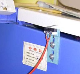
An adjustable microswitch detects when the lid has been opened.

In the setup that [gafu] has come up with, a cheap laser module (the type from a handheld laser pointer) is moved into the path of the primary laser on an arm that’s actuated by a simple hobby servo. To prevent the primary and visible lasers from firing at the same time, an Arduino is used to control the servo given the current state of the K40’s lid. If the lid of the K40 is open, the primary laser is shutoff and the visible laser is rotated into position so the operator can see where the primary laser’s beam would be hitting. Once the lid is closed, the visible laser rotates out of the way and the primary is powered back up.

Running the cutting or engraving job with the lid of the K40 machine open now let’s [gafu] watch a “dry run” of the entire operation with the visible laser before finally committing to blasting the target with the full power beam.

We’ve covered many hacks and modifications for everyone’s favorite entry-level CO2 laser cutter. From replacing the controller to making it bigger, K40 owners certainly seem like a creative bunch.


Filed under: Arduino Hacks, hardware, Laser Hacks

Look what came out of my USB charger !

Quick Charge, Qualcomm’s power delivery over USB technology, was introduced in 2013 and has evolved over several versions offering increasing levels of power transfer. The current version — QCv3.0 — offers 18 W power at voltage levels between 3.6 V to 20 V.  Moreover, connected devices can negotiate and request any voltage between these two limits in 200 mV steps. After some tinkering, [Vincent Deconinck] succeeded in turning a Quick Charge 3.0 charger into a variable voltage power supply.

His blog post is a great introduction and walk through of the Quick Charge ecosystem. [Vincent] was motivated after reading about [Septillion] and [Hugatry]’s work on coaxing a QCv2.0 charger into a variable voltage source which could output either 5 V, 9 V or 12 V. He built upon their work and added QCv3.0 features to create a new QC3Control library.

To come to grips with what happens under the hood, he first obtained several QC2 and QC3 chargers, hooked them up to an Arduino, and ran the QC2Control library to see how they respond. There were some unexpected results; every time a 5 V handshake request was exchanged during QC mode, the chargers reset, their outputs dropped to 0 V and then settled back to a fixed 5 V output. After that, a fresh handshake was needed to revert to QC mode. Digging deeper, he learned that the Quick Charge system relies on specific control voltages being detected on the D+ and D- terminals of the USB port to determine mode and output voltage. These control voltages are generated using resistor networks connected to the microcontroller GPIO pins. After building a fresh resistor network designed to more closely produce the recommended control voltages, and then optimizing it further to use just two micro-controller pins, he was able to get it to work as expected. Armed with all of this information, he then proceeded to design the QC3Control library, available for download on GitHub.

Thanks to his new library and a dual output QC3 charger, he was able to generate the Jolly Wrencher on his Rigol, by getting the Arduino to quickly make voltage change requests.


Filed under: Arduino Hacks, hardware

A BluePill for Arduino Dependence

Arduinos are helpful but some applications require more than what Arduinos can provide. However, it’s not always easy to make the switch from a developed ecosystem into the abyss that is hardware engineering. [Vadim] noticed this, which prompted him to write a guide to shepherd people on their quest for an Arduino-free environment, one BluePill at a time.

With an extended metaphor comparing Arduino use and physical addiction, [Vadim’s] writing is a joy to read. He chose to focus on the BluePill (aka the next Arduino Killer™) which is a $1.75 ARM board with the form factor of an Arduino Nano. After describing where to get the board and it’s an accompanying programmer, [Vadim] introduces PlatformIO, an alternative to the Arduino IDE. But wait! Before the Arduino die-hards leave, take note that PlatformIO can use all of the “Arduino Language,” so your digitalWrites and analogReads are safe (for now). Like any getting started guide, [Vadim] includes the obligatory blinking an LED program. And, in the end, [Vadim] sets his readers up to be comfortable in the middle ground between Arduino Land and the Wild West.

The debate for/against Arduino has been simmering for quite some time, but most agree that Arduino is a good place to start: it’s simpler and easier than jumping head first. However, at some point, many want to remove their “crippling Arduino dependency” (in the words of [Vadim]) and move on to bigger and better things. If you’re at this point, or still cling to your Uno, swing on over and give Vadim’s post a read. If you’re already in the trenches, head on over and read our posts about the BluePill and PlatformIO which are great complements for [Vadim’s].


Filed under: hardware, news
Hack a Day 02 Sep 12:00