Posts with «display» label

Using older Noritake Itron VFD modules

Introduction

Now and again you come across interesting parts on ebay, from friends or just rooting around in second-hand stores. One example of this was a huge Noritake Itron 40 x 2 character vacuum-fluorescent display from 1994 (or earlier) which was passed on from a client. Originally it looked quite complex, however after spending some time the data sheets were found and it was discovered to have a simple serial interface – and with a little work we’ve got it working, so read on if you’re interested in classic VFDs or have a similar unit.

Getting Started

The model number for our display is CU40026SCPB-T20A. Here’s a quick walk-around, the front:

… the back:

… the interfaces:

… and configuration jumpers:

The serial interface baud rate is determined by the jumpers (above), for example:

So comparing the table above against the jumpers on our module gives us a data speed of 19200 bps with no parity. Great – we can easily create such a connection with a microcontroller with a serial output and 5V logic levels; for our examples we’ll use an Arduino-compatible board.

Wiring up the VFD is simple – see the white jumpers labelled CN2 as shown previously. Pin 1 is 5V (you need an external supply that can offer up to 700 mA), pin 2 to Arduino digital pin 7, and pin 3 to Arduino and power supply GND. We use Arduino D7 with software serial instead of TX so that the display doesn’t display garbage when a sketch is being uploaded. Then it’s a matter of simply sending text to the display, for example here’s a quick demonstration sketch:

// Working with Noritake Itron VFD modules - model CU40026SCPB-T20A
// John Boxall 2013

#include <SoftwareSerial.h>
SoftwareSerial VFD(6,7); // RX, TX

void setup()
{
  VFD.begin(19200);
}

void loop()
{
  VFD.print("Hello, world. This is a Noritake VFD "); // You can blast out text 
  do {} while (1);
}

… and the results:

If you’re not keen on the colour or intensity of the display, try some Perspex over the top – for example:

Controlling the display

At this point you’ll need the data sheet, there’s a couple you can download: data sheet onedata sheet two. As you saw previously, writing text is very simple – just use .print functions. However you may want to send individual characters, as well as special commands to control aspects of the display. These are outlined in the data sheet – see the “Software Commands” and “Character Fonts” tables.

If you need to send single commands – for example “clear display” which is 0x0E, use a .write command, such as:

VFD.write(0x0E); // clear display

Some commands are in the format of escape codes (remember those?) so you need to send ESC then the following byte, for example to change the brightness to 50%:

VFD.write(0x1B); // ESC
    VFD.write(0x4C); // brightness
    VFD.write(0x40); // 50% brightness

Armed with that knowledge and the data sheets you can now execute all the commands. According to the data sheet it is possible to change fonts however no matter what the hardware jumper or command we tried it wouldn’t budge from the Japanese katakana font. Your screen may vary. If you use the “screen priority write” function heed the data sheet with respect to the extended “busy” time by delaying subsequent writes to the display by a millisecond.

 Putting it all together

Instead of explaining each and every possible command, I’ve put the common ones inside documented functions in the demonstration sketch below, which is followed by a quick video of the sketch in operation.

// Working with Noritake Itron VFD modules - model CU40026SCPB-T20A
// John Boxall 2013

#include <SoftwareSerial.h>
SoftwareSerial VFD(6,7); // rx, tx

void setup()
{
  VFD.begin(19200); // set speed for software serial port 
  resetVFD();  
  VFDclearsceen();
//  VFD.write(0x12); // vertical scroll mode (on)
}

void resetVFD()
// performs a software reset on the VFD controller
{
  VFD.write(0x1B); // ESC
  VFD.write(0x49); // software reset
}

void VFDnewline()
// moves cursor to start of next line
{
  VFD.write(0x0D); // carriage return
  VFD.write(0x0A); // line feed
}

void VFDclearsceen()
// moves cursor to top-left and clears display
{
  VFD.write(0x0E); // clear display 
  VFD.write(0x0C); // form feed - cursor to top-left
}

void VFDbrightness(int amount)
// sets VFD brightness - 25/50/75/100%
// uses ESC sequences
{
  switch(amount)
  {
  case 25:
    VFD.write(0x1B); // ESC
    VFD.write(0x4C); // brightness
    VFD.print(0); // 25% brightness
    break;
  case 50:
    VFD.write(0x1B); // ESC
    VFD.write(0x4C); // brightness
    VFD.write(0x40); // 50% brightness
    break;
  case 75:
    VFD.write(0x1B); // ESC
    VFD.write(0x4C); // brightness
    VFD.write(0x80); // 75% brightness
    break;
  case 100:
    VFD.write(0x1B); // ESC
    VFD.write(0x4C); // brightness
    VFD.write(0xC0); // 100% brightness
  }
}

void VFDchars()
// run through characters for selected font
{
  for (int i = 21 ; i < 256; i++)
  {
    VFD.write(0x16); // underline cursor off
    VFD.write(i);
    delay(100);
  }
}

void moveCursor(byte position)
// moves the cursor - top row is 0~39, bottom row is 40~79
// vertical scroll mode must be turned off if used
{
    VFD.write(0x1B); // ESC
    VFD.write(0x48); // move cursor 
    VFD.write(position); // location
}

void loop()
{
  VFD.write(0x16); // underline cursor off
  VFD.print("Hello, world - line one."); // You can blast out text 
  delay(1000);      
  VFDnewline();
  VFD.print("Hello, world - line two."); 
  delay(1000);    
  VFDclearsceen();
  VFDbrightness(25);
  VFD.print("*** 25% brightness ***");   
  delay(1000);
  VFDclearsceen();  
  VFDbrightness(50);
  VFD.print("*** 50% brightness ***");     
  delay(1000);
  VFDclearsceen();   
  VFDbrightness(75);
  VFD.print("*** 75% brightness ***");       
  delay(1000);
  VFDclearsceen();   
  VFDbrightness(100);
  VFD.print("*** 100% brightness ***");         
  delay(1000);
  VFDclearsceen();

  VFDchars();
  VFDclearsceen();

  for (int i = 0; i < 80; i++)
  {
    VFD.write(0x16); // underline cursor off
    moveCursor(i);
    VFD.print("X");
    delay(100);
    moveCursor(i);    
    VFD.print(" ");    
  }
  VFDclearsceen();
}


Conclusion

We hope you found this interesting and helpful. And if you have an inexpensive source for these old displays, let us know in the comments. Full-sized images are on flickr. And if you made it this far – check out my new book “Arduino Workshop” from No Starch Press.

In the meanwhile have fun and keep checking into tronixstuff.com. Why not follow things on twitterGoogle+, subscribe  for email updates or RSS using the links on the right-hand column? And join our friendly Google Group – dedicated to the projects and related items on this website. Sign up – it’s free, helpful to each other –  and we can all learn something.

The post Using older Noritake Itron VFD modules appeared first on tronixstuff.

Tutorial – Arduino and MC14489 LED Display Driver

Learn how to use MC14489 LED display driver ICs with Arduino in chapter fifty-one of a series originally titled “Getting Started/Moving Forward with Arduino!” by John Boxall – A tutorial on the Arduino universe. The first chapter is here, the complete series is detailed here.

Updated 12/05/2013

Introduction

Recently we’ve been looking at alternatives to the MAX7219 LED display driver IC due to pricing and availability issues (stay tuned for that one) – and came across an old but still quite useful IC – the MC14489 from Motorola (now Freescale Semiconductor). The MC14489 can drive five seven-segment LED numbers with decimal point, or a combination of numbers and separate LEDs. You can also daisy-chain more than one to drive more digits, and it’s controlled with a simple serial data-clock method in the same way as a 74HC595 shift register. Sourcing the MC14489 isn’t too difficult – it’s available from element14, Newark, Digikey, and so on – or if you’re not in a hurry, try the usual suspects like Futurlec.

For the purpose of the tutorial we’ll show you how to send commands easily from your Arduino or compatible board to control a five-digit 7-segment LED display module – and the instructions are quite simple so they should translate easily to other platforms. Once you have mastered the single module, using more than one MC14489 will be just as easy. So let’s get started.

Hardware

Before moving forward, download the data sheet (pdf). You will need to refer to this as you build the circuit(s). And here’s our subject in real life:

For our demonstration display we’ll be using a vintage HP 5082-7415 LED display module. However you can use almost any 7-segment modules as long as they’re common-cathode – for example, Sparkfun part number COM-11405. If you’re using a four-digit module and want an extra digit, you can add another single digit display. If you want a ruler, the design files are here.

Connecting the MC14489 to an LED display isn’t complex at all. From the data sheet consider Figure 9:

Each of the anode control pins from the MC14489 connect to the matching anodes on your display module, and the BANK1~5 pins connect to the matching digit cathode pins on the display module. You can find the MC14489 pin assignments on page 1 of the data sheet. Seeing as this is chapter fifty-one  – by now you should be confident with finding such information on the data sheets, so I will be encouraging you to do a little more of the work.

Interesting point – you don’t need current-limiting resistors. However you do need the resistor Rx – this controls the current flow to each LED segment. But which value to use? You need to find out the forward current of your LED display (for example 20 mA) then check Figure 7 on page 7 of the data sheet:

To be conservative I’m using a value of 2k0 for Rx, however you can choose your own based on the data sheet for your display and the graph above.  Next – connect the data, clock and enable pins of the MC14489 to three Arduino digital pints – for our example we’re using 5, 6 and 7 for data, clock and enable respectively. Then it’s just 5V and GND to Arduino 5V and GND – and put a 0.1uF capacitor between 5V and GND. Before moving on double-check the connections – especially between the MC14489 and the LED display.

Controlling the MC14489

To control the display we need to send data to two registers in the MC14489 – the configuration register  (one byte) and the display register (three bytes). See page 9 of the data sheet for the overview. The MC14489 will understand that if we send out one byte of data it is to send it the configuration register, and if it receives three bytes of data to send it to the display register. To keep things simple we’ll only worry about the first bit (C0) in the configuration register – this turns the display outputs on or off. To do this, use the following:

digitalWrite(enable, LOW);
shiftOut(data, clock, MSBFIRST, B00000001); // used binary for clarity, however you can use decimal or hexadecimal numbers
digitalWrite(enable, HIGH);
delay(10);

and to turn it off, send bit C0 as zero. The small delay is necessary after each command.

Once you have turned the display on – the next step is to send three bytes of data which represent the numbers to display and decimal points if necessary. Review the table on page 8 of the data sheet. See how they have the binary nibble values for the digits in the third column. Thankfully the nibble for each digit is the binary value for that digit. Furthermore you might want to set the decimal point – that is set using three bits in the first nibble of the three bytes (go back to page 9 and see the display register). Finally you can halve the brightness by setting the very first bit to zero (or one for full brightness).

As an example for that – if you want to display 5.4321 the three bytes of data to send in binary will be:

1101 0101 0100 0011 0010 0001

Let’s break that down. The first bit is 1 for full brightness, then the next three bits (101) turn on the decimal point for BANK5 (the left-most digit). Then you have five nibbles of data, one for each of the digits from left to right. So there’s binary for 5, then four, then three, then two, then one.

digitalWrite(enable, LOW); 
shiftOut(data, clock, MSBFIRST, B11010101); // D23~D16 
shiftOut(data, clock, MSBFIRST, B01000011); // D15~D8
shiftOut(data, clock, MSBFIRST, B00100001); // D7~D0
digitalWrite(enable, HIGH);
delay(10);

To demonstrate everything described so far, it’s been neatly packaged into our first example sketch:

// Example 51.1
// Motorola MC14489 with HP 5082-7415 5-digit, 7-segment LED display
// 2k0 resistor on MC14489 Rx pin
// John Boxall 2013 CC by-sa-nc
// define pins for data from Arduino to MC14489
// we treat it just like a 74HC595
int data = 5;
int clock = 6;
int enable = 7;
void setup()
{
 pinMode(data, OUTPUT);
 pinMode(enable, OUTPUT);
 pinMode(clock, OUTPUT);
 displayOn(); // display defaults to off at power-up
}
void displayTest1()
// displays 5.4321
{
 digitalWrite(enable, LOW); // send 3 bytes to display register. See data sheet page 9
 // you can also insert decimal or hexadecimal numbers in place of the binary numbers
 // we're using binary as you can easily match the nibbles (4-bits) against the table
 // in data sheet page 8
 shiftOut(data, clock, MSBFIRST, B11010101); // D23~D16
 shiftOut(data, clock, MSBFIRST, B01000011); // D15~D8
 shiftOut(data, clock, MSBFIRST, B00100001); // D7~D0
 digitalWrite(enable, HIGH);
 delay(10);
}
void displayTest2()
// displays ABCDE
{
 digitalWrite(enable, LOW); // send 3 bytes to display register. See data sheet page 9
 // you can also insert decimal or hexadecimal numbers in place of the binary numbers
 // we're using binary as you can easily match the nibbles (4-bits) against the table
 // in data sheet page 8
 shiftOut(data, clock, MSBFIRST, B10001010); // D23~D16
 shiftOut(data, clock, MSBFIRST, B10111100); // D15~D8
 shiftOut(data, clock, MSBFIRST, B11011110); // D7~D0
 digitalWrite(enable, HIGH);
 delay(10);
}
void displayOn()
// turns on display
{
 digitalWrite(enable, LOW);
 shiftOut(data, clock, MSBFIRST, B00000001);
 digitalWrite(enable, HIGH);
 delay(10);
}
void displayOff()
// turns off display
{
 digitalWrite(enable, LOW);
 shiftOut(data, clock, MSBFIRST, B00000000);
 digitalWrite(enable, HIGH);
 delay(10);
}
void loop()
{
 displayOn();
 displayTest1();
 delay(1000);
 displayTest2();
 delay(1000);
 displayOff();
 delay(500);
}

… with the results in the following video:


Now that we can display numbers and a few letters with binary, life would be easier if there was a way to take a number and just send it to the display.

So consider the following function that takes an integer between 0 and 99999, does the work and sends it to the display:

void displayIntLong(long x)
// takes a long between 0~99999 and sends it to the MC14489
{
 int numbers[5];
 byte a=0; 
 byte b=0; 
 byte c=0; // will hold the three bytes to send to the MC14489 

 // first split the incoming long into five separate digits
 numbers[0] = int ( x / 10000 ); // left-most digit (will be BANK5)
 x = x % 10000; 
 numbers[1] = int ( x / 1000 );
 x = x % 1000; 
 numbers[2] = int ( x / 100 );
 x = x % 100; 
 numbers[3] = int ( x / 10 );
 x = x % 10; 
 numbers[4] = x % 10; // right-most digit (will be BANK1)

 // now to create the three bytes to send to the MC14489
 // build byte c which holds digits 4 and 5
 c = numbers[3];
 c = c << 4; // move the nibble to the left
 c = c | numbers[4];
 // build byte b which holds digits 3 and 4
 b = numbers [1];
 b = b << 4;
 b = b | numbers[2];
 // build byte a which holds the brightness bit, decimal points and digit 1
 a = B10000000 | numbers[0]; // full brightness, no decimal points

 // now send the bytes to the MC14489
 digitalWrite(enable, LOW);
 shiftOut(data, clock, MSBFIRST, a);
 shiftOut(data, clock, MSBFIRST, b);
 shiftOut(data, clock, MSBFIRST, c); 
 digitalWrite(enable, HIGH);
 delay(10); 
}

So how does that work? First it splits the 5-digit number into separate digits and stores them in the array numbers[]. It then places the fourth digit into a byte, then moves the data four bits to the left – then we bitwise OR the fifth digit into the same byte. This leaves us with a byte of data containing the nibbles for the fourth and fifth digit. The process is repeated for digits 2 and 3. Finally the brightness bit and decimal point bits are assigned to another byte which then has the first digit’s nibble OR’d into it. Which leaves us with bytes a, b and c ready to send to the MC14489. Note that there isn’t any error-checking – however you could add a test to check that the number to be displayed was within the parameter, and if not either switch off the display (see example 51.1) or throw up all the decimal points or … whatever you want.

You can download the demonstration sketch for the function – Example 51.2, and view the results in the following video:

You can also display the letters A to F by sending the values 10 to 15 respectivel to each digit’s nibble. However that would be part of a larger application, which you can (hopefully) by now work out for yourself. Furthermore there’s some other characters that can be displayed – however trying to display the alphabet using 7-segment displays is somewhat passé. Instead, get some 16-segment LED modules or an LCD.

Finally, you can cascade more than one MC14489 to control more digits. Just run a connection from the data out pin on the first MC14889 to the data pin of the second one, and all the clock and enable lines together. Then send out more data – see page 11 of the data sheet. If you’re going to do that in volume other ICs may be a cheaper option and thus lead you back to the MAX7219.

Conclusion

For a chance find the MC14489 is a fun an inexpensive way to drive those LED digit displays. We haven’t covered every single possible option or feature of the part – however you will now have the core knowledge to go further with the MC14489 if you need to move further with it. And if you enjoy my tutorials, or want to introduce someone else to the interesting world of Arduino – check out my new book “Arduino Workshop” from No Starch Press.

In the meanwhile have fun and keep checking into tronixstuff.com. Why not follow things on twitterGoogle+, subscribe  for email updates or RSS using the links on the right-hand column? And join our friendly Google Group – dedicated to the projects and related items on this website. Sign up – it’s free, helpful to each other –  and we can all learn something.

The post Tutorial – Arduino and MC14489 LED Display Driver appeared first on tronixstuff.

Tutorial – Arduino and ILI9325 colour TFT LCD modules

Learn how to use inexpensive ILI9325 colour TFT LCD modules in chapter fifty of a series originally titled “Getting Started/Moving Forward with Arduino!” by John Boxall – A tutorial on the Arduino universe. The first chapter is here, the complete series is detailed here.

Introduction

Colour TFT LCD modules just keep getting cheaper, so in this tutorial we’ll show you how to get going with some of the most inexpensive modules we could find. The subject of our tutorial is a 2.8″ 240 x 320 TFT module with the ILI9325 LCD controller chip. If you look in ebay this example should appear pretty easily, here’s a photo of the front and back to help identify it:

There is also the line “HY-TFT240_262k HEYAODZ110510” printed on the back of the module. They should cost less than US$10 plus shipping. Build quality may not be job number one at the factory so order a few, however considering the cost of something similar from other retailers it’s cheap insurance. You’ll also want sixteen male to female jumper wires to connect the module to your Arduino.

Getting started

To make life easier we’ll use an Arduino library “UTFT” written for this and other LCD modules. It has been created by Henning Karlsen and can be downloaded from his website. If you can, send him a donation – this library is well worth it. Once you’ve downloaded and installed the UTFT library, the next step is to wire up the LCD for a test.

Run a jumper from the following LCD module pins to your Arduino Uno (or compatible):

  • DB0 to DB7 > Arduino D0 to D7 respectively
  • RD > 3.3 V
  • RSET > A2
  • CS > A3
  • RW > A4
  • RS > A5
  • backlight 5V > 5V
  • backlight GND > GND

Then upload the following sketch – Example 50.1. You should be presented with the following on your display:

If you’re curious, the LCD module and my Eleven board draws 225 mA of current. If that didn’t work for you, double-check the wiring against the list provided earlier. Now we’ll move forward and learn how to display text and graphics.

Sketch preparation

You will always need the following before void setup():

#include "UTFT.h"
UTFT myGLCD(ILI9325C,19,18,17,16); // for Arduino Uno

and in void setup():

myGLCD.InitLCD(orientation); 
myGLCD.clrScr();

with the former command, change orientation to either LANDSCAPE to PORTRAIT depending on how you’ll view the screen. You may need further commands however these are specific to features that will be described below. The function .clrScr() will clear the screen.

Displaying Text

There are three different fonts available with the library. To use them add the following three lines before void setup():

extern uint8_t SmallFont[];
extern uint8_t BigFont[];
extern uint8_t SevenSegNumFont[];

When displaying text you’ll need to define the foreground and background colours with the following:

myGLCD.setColor(red, green, blue); 
myGLCD.setBackColor(red, green, blue);

Where red, green and blue are values between zero and 255. So if you want white use 255,255,255 etc. For some named colours and their RGB values, click here. To select the required font, use one of the following:

myGLCD.setFont(SmallFont); // Allows 20 rows of 40 characters
myGLCD.setFont(BigFont); // Allows 15 rows of 20 characters
myGLCD.setFont(SevenSegNumFont); // allows display of 0 to 9 over four rows

Now to display the text use the function:

myGLCD.print("text to display",x, y);

where text is what you’d like to display, x is the horizontal alignment (LEFT, CENTER, RIGHT) or position in pixels from the left-hand side of the screen and y is the starting point of the top-left of the text. For example, to start at the top-left of the display y would be zero. You can also display a string variable instead of text in inverted commas.

You can see all this in action with the following sketch – Example 50.2, which is demonstrated in the following video:

Furthremore, you can also specify the angle of display, which gives a simple way of displaying text on different slopes. Simply add the angle as an extra parameter at the end:

myGLCD.print("Hello, world", 20, 20, angle);

Again, see the following sketch – Example 50.2a, and the results below:

Displaying Numbers

Although you can display numbers with the text functions explained previously, there are two functions specifically for displaying integers and floats.

You can see these functions in action with the following sketch – Example 50.3, with an example of the results below:

Displaying Graphics

There’s a few graphic functions that can be used to create required images. The first is:.

myGLCD.fillScr(red, green, blue);

which is used the fill the screen with a certain colour. The next simply draws a pixel at a specified x,y location:

myGLCD.drawPixel(x,y);

Remember that the top-left of the screen is 0,0. Moving on, to draw a single line, use:

myGLCD.drawLine(x1,0,x2,239);

where the line starts at x1,y1 and finishes at x2,y2. Need a rectangle? Use:

myGLCD.drawRect(x1,y2,x2,y2); // for open rectangles
myGLCD.fillRect(x1,y2,x2,y2); // for filled rectangles

where the top-left of the rectangle is x1,y1 and the bottom-right is x2, y2. You can also have rectangles with rounded corners, just use:

myGLCD.drawRoundRect(x1,y2,x2,y2); // for open rectangles
myGLCD.fillRoundRect(x1,y2,x2,y2); // for filled rectangles

instead. And finally, circles – which are quite easy. Just use:

myGLCD.drawCircle(x,y,r); // draws open circle
myGLCD.fillCircle(x,y,r); // draws a filled circle

where x,y are the coordinates for the centre of the circle, and r is the radius. For a quick demonstration of all the graphic functions mentioned so far, see Example 50.4 – and the following video:

Displaying bitmap images

If you already have an image in .gif, .jpg or .png format that’s less than 300 KB in size, this can be displayed on the LCD. To do so, the file needs to be converted to an array which is inserted into your sketch. Let’s work with a simple example to explain the process. Below is our example image:

Save the image of the puppy somewhere convenient, then visit this page. Select the downloaded file, and select the .c and Arduino radio buttons, then click “make file”. After a moment or two a new file will start downloading. When it arrives, open it with a text editor – you’ll see it contains a huge array and another #include statement – for example:

Past the #include statement and the array into your sketch above void setup(). After doing that, don’t be tempted to “autoformat” the sketch in the Arduino IDE. Now you can use the following function to display the bitmap on the LCD:

myGLCD.drawBitmap(x,y,width,height, name, scale);

Where x and y are the top-left coordinates of the image, width and height are the … width and height of the image, and name is the name of the array. Scale is optional – you can double the size of the image with this parameter. For example a value of two will double the size, three triples it – etc. The function uses simple interpolation to enlarge the image, and can be a clever way of displaying larger images without using extra memory. Finally, you can also display the bitmap on an angle – using:

myGLCD.drawBitmap(x,y,width,height, name, angle, cx, cy);

where angle is the angle of rotation and cx/cy are the coordinates for the rotational centre of the image.

The bitmap functions using the example image have been used in the following sketch – Example 50.5, with the results in the following video:

Unfortunately the camera doesn’t really do the screen justice, it looks much better with the naked eye.

What about the SD card socket and touch screen?

The SD socket didn’t work, and I won’t be working with the touch screen at this time.

Conclusion

So there you have it – an incredibly inexpensive and possibly useful LCD module. Thank you to Henning Karlsen for his useful library, and if you found it useful – send him a donation via his page.

In the meanwhile have fun and keep checking into tronixstuff.com. Why not follow things on twitterGoogle+, subscribe  for email updates or RSS using the links on the right-hand column? And join our friendly Google Group – dedicated to the projects and related items on this website. Sign up – it’s free, helpful to each other –  and we can all learn something.

The post Tutorial – Arduino and ILI9325 colour TFT LCD modules appeared first on tronixstuff.

Tronixstuff 26 Apr 02:31

Project: Clock Four – Scrolling text clock

Introduction

Time for another instalment in my highly-irregular series of irregular clock projects.  In this we have “Clock Four” – a scrolling text clock. After examining some Freetronics Dot Matrix Displays in the stock, it occurred to me that it would be neat to display the time as it was spoken (or close to it) – and thus this the clock was born. It is a quick project – we give you enough to get going with the hardware and sketch, and then you can take it further to suit your needs.

Hardware

You’ll need three major items – An Arduino Uno-compatible board, a real-time clock circuit or module using either a DS1307 or DS3232 IC, and a Freetronics DMD. You might want an external power supply, but we’ll get to that later on.

The first stage is to fit your real-time clock. If you are unfamiliar with the operation of real-time clock circuits, check out the last section of this tutorial. You can build a RTC circuit onto a protoshield or if you have a Freetronics Eleven, it can all fit in the prototyping space as such:

If you have an RTC module, it will also fit in the same space, then you simply run some wires to the 5V, GND, A4 (for SDA) and A5 (for SCL):

By now I hope you’re thinking “how do you set the time?”. There’s two answers to that question. If you’re using the DS3232 just set it in the sketch (see below) as the accuracy is very good, you only need to upload the sketch with the new time twice a year to cover daylight savings (unless you live in Queensland). Otherwise add a simple user-interface – a couple of buttons could do it, just as we did with Clock Two. Finally you just need to put the hardware on the back of the DMD. There’s plenty of scope to meet your own needs, a simple solution might be to align the control board so you can access the USB socket with ease – and then stick it down with some Sugru:

With regards to powering the clock – you can run ONE DMD from the Arduino, and it runs at a good brightness for indoor use. If you want the DMD to run at full, retina-burning brightness you need to use a separate 5 V 4 A power supply. If you’re using two DMDs – that goes to 8 A, and so on. Simply connect the external power to one DMD’s terminals (connect the second or more DMDs to these terminals):

The Arduino Sketch

You can download the sketch from here. Please use IDE v1.0.1 . The sketch has the usual functions to set and retrieve the time from DS1307/3232 real-time clock ICs, and as usual with all our clocks you can enter the time information into the variables in void setup(), then uncomment setDateDs1307(), upload the sketch, re-comment setDateDs1307, then upload the sketch once more. Repeat that process to re-set the time if you didn’t add any hardware-based user interface.

Once the time is retrieved in void loop(), it is passed to the function createTextTime(). This function creates the text string to display by starting with “It’s “, and then determines which words to follow depending on the current time. Finally the function drawText() converts the string holding the text to display into a character variable which can be passed to the DMD.

And here it is in action:

Conclusion

This was a quick project, however I hope you found it either entertaining or useful – and another random type of clock that’s easy to reproduce or modify yourself. We’re already working on another one which is completely different, so stay tuned.

In the meanwhile have fun and keep checking into tronixstuff.com. Why not follow things on twitterGoogle+, subscribe  for email updates or RSS using the links on the right-hand column? And join our friendly Google Group – dedicated to the projects and related items on this website. Sign up – it’s free, helpful to each other –  and we can all learn something.

The post Project: Clock Four – Scrolling text clock appeared first on tronixstuff.

Arduino and KTM-S1201 LCD modules

Learn how to use very inexpensive KTM-S1201 LCD modules in this edition of our Arduino tutorials. This is chapter forty-nine of a series originally titled “Getting Started/Moving Forward with Arduino!” by John Boxall – A tutorial on the Arduino universe. The first chapter is here, the complete series is detailed here.

Introduction

After looking for some displays to use with another (!) clock, I came across some 12-digit numeric LCD displays. They aren’t anything flash, and don’t have a back light –  however they were one dollar each. How could you say no to that? So I ordered a dozen to try out. The purpose of this tutorial is to show you how they are used with an Arduino in the simplest manner possible.

Moving forward – the modules look like OEM modules for desktop office phones from the 1990s:

With a quick search on the Internet you will find a few sellers offering them for a dollar each. The modules (data sheet) use the NEC PD7225 controller IC (data sheet):

They aren’t difficult to use, so I’ll run through set up and operation with a few examples.

Hardware setup

First you’ll need to solder some sort of connection to the module – such as 2×5 header pins. This makes it easy to wire it up to a breadboard or a ribbon cable:

The rest of the circuitry is straight-forward. There are ten pins in two rows of five, and with the display horizontal and the pins on the right, they are numbered as such:

Now make the following connections:

  • LCD pin 1 to 5V
  • LCD pin 2 to GND
  • LCD pin 3 to Arduino D4
  • LCD pin 4 to Arduino D5
  • LCD pin 5 to Arduino D6
  • LCD pin 6 to Arduino D7
  • LCD pin 7 – not connected
  • LCD pin 8 – Arduino D8
  • LCD pin 9 to the centre pin of a 10k trimpot – whose other legs connect to 5V and GND. This is used to adjust the contrast of the LCD.

The Arduino digital pins that are used can be changed – they are defined in the header file (see further on). If you were curious as to how low-current these modules are:

That’s 0.689 mA- not bad at all. Great for battery-powered operations. Now that you’ve got the module wired up, let’s get going with some demonstration sketches.

Software setup

The sketches used in this tutorial are based on work by Jeff Albertson and Robert Mech, so kudos to them – however we’ve simplified them a little to make use easier. We’ll just cover the functions required to display data on the LCD. However feel free to review the sketches and files along with the controller chip datasheet as you’ll get an idea of how the controller is driven by the Arduino.

When using the LCD module you’ll need a header file in the same folder as your sketch. You can download the header file from here. Then every time you open a sketch that uses the header file, it should appear in a tab next to the main sketch, for example:

There’s also a group of functions and lines required in your sketch. We’ll run through those now – so download the first example sketch, add the header file and upload it. Your results should be the same as the video below:

So how did that work? Take a look at the sketch you uploaded.  You need all the functions between the two lines of “////////////////////////” and also the five lines in void setup(). Then you can display a string of text or numbers using

ktmWriteString();

which was used in void loop(). You can use the digits 0~9, the alphabet (well, what you can do with 7-segments), the degrees symbol (use an asterix – “*”) and a dash (use  – “-“). So if your sketch can put together the data to display in a string, then that’s taken care of.

If you want to clear the screen, use:

ktmCommand(_ClearDsp);

Next – to individually place digits on the screen, use the function:

tmPrnNumb(n,p,d,l);

Where n is the number to be displayed (zero or a positive integer), p is the position on the LCD for the number’s  (the positions from left to right are 11 to 0…), d is the number of digits to the right of the decimal point (leave as zero if you don’t want a decimal point), and l is the number of digits being displayed for n. When you display digits using this function you can use more than one function to compose the number to be displayed – as this function doesn’t clear the screen.

To help get your head around it, the following example sketch (download) has a variety of examples in void loop(). You can watch this example in the following video:

Conclusion

So there you have it – an incredibly inexpensive and possibly useful LCD module. Thank you to Jeff Albertson and Robert Mech for their help and original code.

In the meanwhile have fun and keep checking into tronixstuff.com. Why not follow things on twitterGoogle+, subscribe  for email updates or RSS using the links on the right-hand column? And join our friendly Google Group – dedicated to the projects and related items on this website. Sign up – it’s free, helpful to each other –  and we can all learn something.

The post Arduino and KTM-S1201 LCD modules appeared first on tronixstuff.

Tutorial: Arduino and the MSGEQ7 Spectrum Analyzer

This is a tutorial on using the MSGEQ7 Spectrum Analyser with Arduino, and chapter forty-eight of a series originally titled “Getting Started/Moving Forward with Arduino!” by John Boxall – A tutorial on the Arduino universe. The first chapter is here, the complete series is detailed here.

Updated 10/11/2014

In this article we’re going to explain how to make simple spectrum analysers with an Arduino-style board. (Analyser? Analyzer? Take your pick).

First of all, what is a spectrum analyser? Good question. Do you remember what  this is?

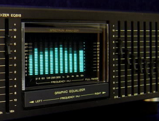
It’s a mixed graphic equaliser/spectrum analyser deck for a hi-fi system. The display in the middle is the spectrum analyser, and roughly-speaking it shows the strength of  different frequencies in the music being listened to – and looked pretty awesome doing it. We can recreate displays similar to this for entertainment and also as a base for creative lighting effects. By working through this tutorial you’ll have the base knowledge to recreate these yourself.

We’ll be using the MSGEQ7 “seven band graphic equaliser IC” from Mixed Signal Integration. Here’s the MSGEQ7 data sheet (.pdf).  This little IC can accept a single audio source, analyse seven frequency bands of the audio, and output a DC representation of each frequency band. This isn’t super-accurate or calibrated in any way, but it works. You can get the IC separately, for example:


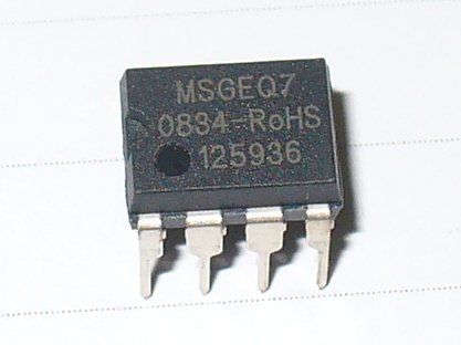
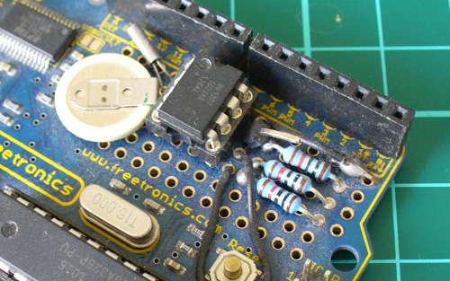
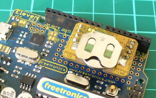
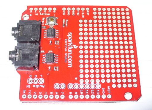
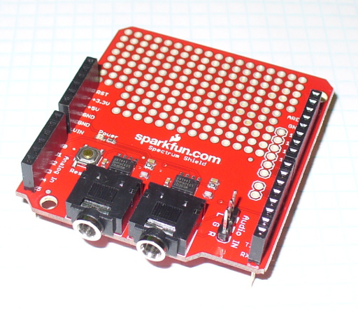
and then build your own circuit around it… or like most things in the Arduino world – get a shield. In this case, a derivative of the original Bliptronics shield by Sparkfun. It’s designed to pass through stereo audio via 3.5mm audio sockets and contains two MSGEQ7s, so we can do a stereo analyser:

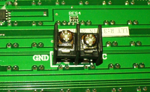
As usual Sparkfun have saved a few cents by not including the stackable header sockets, so you’ll need to buy and solder those in yourself. There is also space for three header pins for direct audio input (left, right and common), which are useful – so if you can add those as well.

So now you have a shield that’s ready for use. Before moving forward let’s examine how the MSGEQ7 works for us. As mentioned earlier, it analyses seven frequency bands. These are illustrated in the following graph from the data sheet:

It will return the strengths of the audio at seven points – 63 Hz, 160 Hz, 400 Hz, 1 kHz, 2.5 kHz, 6.25 kHz and 16 kHz – and as you can see there is some overlap between the bands. The strength is returned as a DC voltage – which we can then simply measure with the Arduino’s analogue input and create a display of some sort. At this point audio purists, Sheldonites and RF people might get a little cranky, so once again – this is more for visual indication than any sort of calibration device.

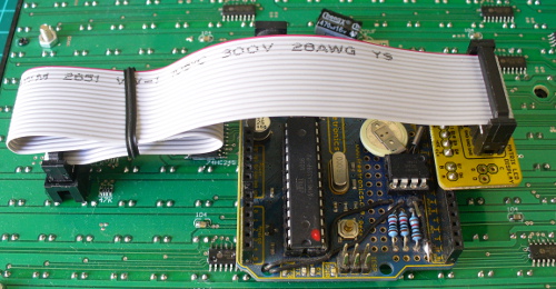
However as an 8-pin IC a different approach is required to get the different levels. The IC will sequentially give out the levels for each band on pin 3- e.g. 63 Hz then 160 Hz then 400 Hz then 1 kHz then 2.5 kHz then 6.25 kHz  then 16 kHz then back to 63 Hz and so on. To start this sequence we first reset the IC by pulsing the RESET pin HIGH then low. This tells the IC to start at the first band. Next, we set the STROBE pin to LOW, take the DC reading from pin 3 with analogue input, store the value in a variable (an array), then set the STROBE pin HIGH. We repeat the strobe-measure sequence six more times to get the rest of the data, then RESET the IC and start all over again. For the visual learners consider the diagram below from the data sheet:

To demonstrate this process, consider the function

readMSGEQ7()

in the following example sketch:

// Example 48.1 - tronixstuff.com/tutorials > chapter 48 - 30 Jan 2013 
// MSGEQ7 spectrum analyser shield - basic demonstration
int strobe = 4; // strobe pins on digital 4
int res = 5; // reset pins on digital 5
int left[7]; // store band values in these arrays
int right[7];
int band;
void setup()
{
 Serial.begin(115200);
 pinMode(res, OUTPUT); // reset
 pinMode(strobe, OUTPUT); // strobe
 digitalWrite(res,LOW); // reset low
 digitalWrite(strobe,HIGH); //pin 5 is RESET on the shield
}
void readMSGEQ7()
// Function to read 7 band equalizers
{
 digitalWrite(res, HIGH);
 digitalWrite(res, LOW);
 for(band=0; band <7; band++)
 {
 digitalWrite(strobe,LOW); // strobe pin on the shield - kicks the IC up to the next band 
 delayMicroseconds(30); // 
 left[band] = analogRead(0); // store left band reading
 right[band] = analogRead(1); // ... and the right
 digitalWrite(strobe,HIGH); 
 }
}
void loop()
{
 readMSGEQ7();
 // display values of left channel on serial monitor
 for (band = 0; band < 7; band++)
 {
 Serial.print(left[band]);
 Serial.print(" ");
 }
 Serial.println();
// display values of right channel on serial monitor
 for (band = 0; band < 7; band++)
 {
 Serial.print(right[band]);
 Serial.print(" ");
 }
 Serial.println();
}

If you follow through the sketch, you can see that it reads both left- and right-channel values from the two MSGEQ7s on the shield, then stores each value in the arrays left[] and right[]. These values are then sent to the serial monitor for display – for example:

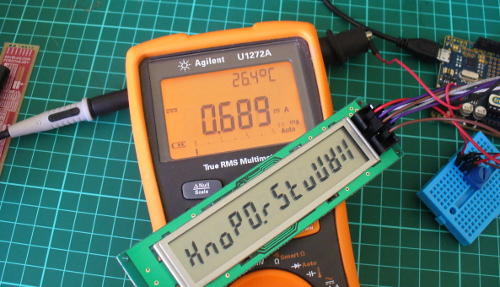
If you have a function generator, connect the output to one of the channels and GND – then adjust the frequency and amplitude to see how the values change. The following video clip is a short demonstration of this – we set the generator to 1 kHz and adjust the amplitude of the signal. To make things easier to read we only measure and display the left channel:


Keep an eye on the fourth column of data – this is the analogRead() value returned by the Arduino when reading the 1khz frequency band. You can also see the affect on the other bands around 1 kHz as we increase and decrease the frequency. However that wasn’t really visually appealing – so now we’ll create a small and large graphical version.

First we’ll use an inexpensive LCD, the I2C model from akafugu reviewed previously. To save repeating myself, also review how to create custom LCD characters from here.

With the LCD with have two rows of sixteen characters. The plan is to use the top row for the levels, the left-channel’s on … the left, and the right on the right. Each character will be a little bar graph for the level. The bottom row can be for a label. We don’t have too many pixels to work with, but it’s a compact example:

We have eight rows for each character, and the results from an analogueRead() fall between 0 and 1023. So that’s 1024 possible values spread over eight sections. Thus each row of pixels in each character will represent 128 “units of analogue read” or around 0.63 V if the Arduino is running from true 5 V (remember your AREF notes?). The sketch will again read the values from the MSGEQ7, feed them into two arrays – then display the required character in each band space  on the LCD.

Here’s the resulting sketch:

// Example 48.2 - tronixstuff.com/tutorials > chapter 48 - 30 Jan 2013 
// MSGEQ7 spectrum analyser shield and I2C LCD from akafugu
// for akafugu I2C LCD
#include "Wire.h"
#include "TWILiquidCrystal.h"
LiquidCrystal lcd(50);
// create custom characters for LCD
byte level0[8] = { 0b00000, 0b00000, 0b00000, 0b00000, 0b00000, 0b00000, 0b00000, 0b11111};
byte level1[8] = { 0b00000, 0b00000, 0b00000, 0b00000, 0b00000, 0b00000, 0b11111, 0b11111};
byte level2[8] = { 0b00000, 0b00000, 0b00000, 0b00000, 0b00000, 0b11111, 0b11111, 0b11111};
byte level3[8] = { 0b00000, 0b00000, 0b00000, 0b00000, 0b11111, 0b11111, 0b11111, 0b11111};
byte level4[8] = { 0b00000, 0b00000, 0b00000, 0b11111, 0b11111, 0b11111, 0b11111, 0b11111};
byte level5[8] = { 0b00000, 0b00000, 0b11111, 0b11111, 0b11111, 0b11111, 0b11111, 0b11111};
byte level6[8] = { 0b00000, 0b11111, 0b11111, 0b11111, 0b11111, 0b11111, 0b11111, 0b11111};
byte level7[8] = { 0b11111, 0b11111, 0b11111, 0b11111, 0b11111, 0b11111, 0b11111, 0b11111};
int strobe = 4; // strobe pins on digital 4
int res = 5; // reset pins on digital 5
int left[7]; // store band values in these arrays
int right[7];
int band;
void setup()
{
 Serial.begin(9600);
 // setup LCD and custom characters
 lcd.begin(16, 2);
 lcd.setContrast(24);
 lcd.clear();
lcd.createChar(0,level0);
 lcd.createChar(1,level1);
 lcd.createChar(2,level2);
 lcd.createChar(3,level3);
 lcd.createChar(4,level4);
 lcd.createChar(5,level5);
 lcd.createChar(6,level6);
 lcd.createChar(7,level7);
 lcd.setCursor(0,1);
 lcd.print("Left");
 lcd.setCursor(11,1);
 lcd.print("Right");
 pinMode(res, OUTPUT); // reset
 pinMode(strobe, OUTPUT); // strobe
 digitalWrite(res,LOW); // reset low
 digitalWrite(strobe,HIGH); //pin 5 is RESET on the shield
}
void readMSGEQ7()
// Function to read 7 band equalizers
{
 digitalWrite(res, HIGH);
 digitalWrite(res, LOW);
 for( band = 0; band < 7; band++ )
 {
 digitalWrite(strobe,LOW); // strobe pin on the shield - kicks the IC up to the next band 
 delayMicroseconds(30); // 
 left[band] = analogRead(0); // store left band reading
 right[band] = analogRead(1); // ... and the right
 digitalWrite(strobe,HIGH); 
 }
}
void loop()
{
 readMSGEQ7();
// display values of left channel on LCD
 for( band = 0; band < 7; band++ )
 {
 lcd.setCursor(band,0);
 if (left[band]>=895) { lcd.write(7); } else
 if (left[band]>=767) { lcd.write(6); } else
 if (left[band]>=639) { lcd.write(5); } else
 if (left[band]>=511) { lcd.write(4); } else
 if (left[band]>=383) { lcd.write(3); } else
 if (left[band]>=255) { lcd.write(2); } else
 if (left[band]>=127) { lcd.write(1); } else
 if (left[band]>=0) { lcd.write(0); }
 }
 // display values of right channel on LCD
 for( band = 0; band < 7; band++ )
 {
 lcd.setCursor(band+9,0);
 if (right[band]>=895) { lcd.write(7); } else
 if (right[band]>=767) { lcd.write(6); } else
 if (right[band]>=639) { lcd.write(5); } else
 if (right[band]>=511) { lcd.write(4); } else
 if (right[band]>=383) { lcd.write(3); } else
 if (right[band]>=255) { lcd.write(2); } else
 if (right[band]>=127) { lcd.write(1); } else
 if (right[band]>=0) { lcd.write(0); }
 }
}

If you’ve been reading through my tutorials there isn’t anything new to worry about. And now for the demo, with sound –

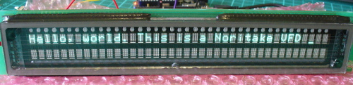
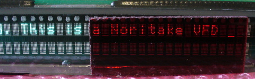
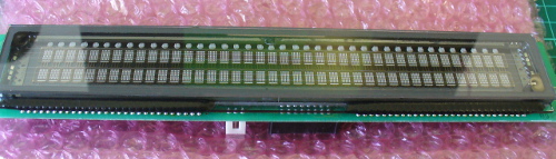
That would look great on the side of a Walkman, however it’s a bit small. Let’s scale it up by using a Freetronics Dot Matrix Display – you may recall these from Clock One. For some background knowledge check the review here.  Don’t forget to use a suitable power supply for the DMD – 5 V at 4 A will do nicely. The DMD contains 16 rows of 32 LEDs. This gives us twice the “resolution” to display each band level if desired. The display style is subjective, so for this example we’ll use a single column of LEDs for each frequency band, with a blank column between each one.

We use a lot of line-drawing statements to display the levels, and clear the DMD after each display. With this and the previous sketches, there could be room for efficiency – however I write these with the beginner in mind. Here’s the sketch:

// Example 48.3 - tronixstuff.com/tutorials > chapter 48 - 30 Jan 2013 
// MSGEQ7 spectrum analyser shield with a Freetronics DMD
// for DMD
#include "DMD.h" // for DMD
#include "SPI.h" // SPI.h must be included as DMD is written by SPI (the IDE complains otherwise)
#include "TimerOne.h"
#include "SystemFont5x7.h" // keep next two lines if you want to add some text
#include "Arial_black_16.h"
DMD dmd(1, 1); // creates instance of DMD to refer to in sketch
void ScanDMD() // necessary interrupt handler for refresh scanning of DMD
{ 
 dmd.scanDisplayBySPI();
}
int strobe = 4; // strobe pins on digital 4
int res = 5; // reset pins on digital 5
int left[7]; // store band values in these arrays
int right[7];
int band;
void setup()
{
 // for DMD
 //initialize TimerOne's interrupt/CPU usage used to scan and refresh the display
 Timer1.initialize( 5000 ); //period in microseconds to call ScanDMD. Anything longer than 5000 (5ms) and you can see flicker.
 Timer1.attachInterrupt( ScanDMD ); //attach the Timer1 interrupt to ScanDMD which goes to dmd.scanDisplayBySPI() 
 dmd.clearScreen( true ); //true is normal (all pixels off), false is negative (all pixels on)

 // for MSGEQ7
 pinMode(res, OUTPUT); // reset
 pinMode(strobe, OUTPUT); // strobe
 digitalWrite(res,LOW); // reset low
 digitalWrite(strobe,HIGH); //pin 5 is RESET on the shield
}
void readMSGEQ7()
// Function to read 7 band equalizers
{
 digitalWrite(res, HIGH);
 digitalWrite(res, LOW);
 for( band = 0; band < 7; band++ )
 {
 digitalWrite(strobe,LOW); // strobe pin on the shield - kicks the IC up to the next band 
 delayMicroseconds(30); // 
 left[band] = analogRead(0); // store left band reading
 right[band] = analogRead(1); // ... and the right
 digitalWrite(strobe,HIGH); 
 }
}
void loop()
{
 int xpos;
 readMSGEQ7();
 dmd.clearScreen( true ); 
 // display values of left channel on DMD
 for( band = 0; band < 7; band++ )
 {
 xpos = (band*2)+1;
 if (left[band]>=895) { dmd.drawLine( xpos, 15, xpos, 1, GRAPHICS_NORMAL ); } else
 if (left[band]>=767) { dmd.drawLine( xpos, 15, xpos, 3, GRAPHICS_NORMAL ); } else
 if (left[band]>=639) { dmd.drawLine( xpos, 15, xpos, 5, GRAPHICS_NORMAL ); } else
 if (left[band]>=511) { dmd.drawLine( xpos, 15, xpos, 7, GRAPHICS_NORMAL ); } else
 if (left[band]>=383) { dmd.drawLine( xpos, 15, xpos, 9, GRAPHICS_NORMAL ); } else
 if (left[band]>=255) { dmd.drawLine( xpos, 15, xpos, 11, GRAPHICS_NORMAL ); } else
 if (left[band]>=127) { dmd.drawLine( xpos, 15, xpos, 13, GRAPHICS_NORMAL ); } else
 if (left[band]>=0) { dmd.drawLine( xpos, 15, xpos, 15, GRAPHICS_NORMAL ); }
 }

 // display values of right channel on DMD
 for( band = 0; band < 7; band++ )
 {
 xpos = (band*2)+18;
 if (right[band]>=895) { dmd.drawLine( xpos, 15, xpos, 1, GRAPHICS_NORMAL ); } else
 if (right[band]>=767) { dmd.drawLine( xpos, 15, xpos, 3, GRAPHICS_NORMAL ); } else
 if (right[band]>=639) { dmd.drawLine( xpos, 15, xpos, 5, GRAPHICS_NORMAL ); } else
 if (right[band]>=511) { dmd.drawLine( xpos, 15, xpos, 7, GRAPHICS_NORMAL ); } else
 if (right[band]>=383) { dmd.drawLine( xpos, 15, xpos, 9, GRAPHICS_NORMAL ); } else
 if (right[band]>=255) { dmd.drawLine( xpos, 15, xpos, 11, GRAPHICS_NORMAL ); } else
 if (right[band]>=127) { dmd.drawLine( xpos, 15, xpos, 13, GRAPHICS_NORMAL ); } else
 if (right[band]>=0) { dmd.drawLine( xpos, 15, xpos, 15, GRAPHICS_NORMAL ); }
 }
}

… and here it is in action:

Conclusion

At this point you have the knowledge to use the MSGEQ7 ICs to create some interesting spectrum analysers for entertainment and visual appeal – now you just choose the type of display enjoy the results. And if you enjoyed this article, or want to introduce someone else to the interesting world of Arduino – check out my book (now in a fourth printing!) “Arduino Workshop”.

Have fun and keep checking into tronixstuff.com. Why not follow things on twitterGoogle+, subscribe  for email updates or RSS using the links on the right-hand column, or join our forum – dedicated to the projects and related items on this website.

The post Tutorial: Arduino and the MSGEQ7 Spectrum Analyzer appeared first on tronixstuff.
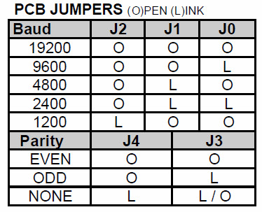
10 seconds count down using Arduino

This is one of my 1st Arduino projects. Along with Arduino, I've used a seven segmeent led display and a piezzo buzzer. First, it beeps to indicate start. Then, counts down from 9 to 0, beeps three times. Finally, it beeps for the last time but this time the beep lasts longer.

A much larger rainbow board of many ping pongs

[George] started with an 8×8 grid, but just couldn’t help himself from upscaling to this 32×16 pixel ping pong ball display. That’s right, It’s a 512 pixel array of fully addressable RGB LEDs diffused with one ping pong ball each.

We featured the predecessor to this project back in January. That one was an 8×8 display using a Rainbowduino as the controller. [George] took what he learned from that build and expanded upon it. The larger display is modular. Each module starts as an 8×8 grid which connects back to the Arduino using a breakout shield with some Ethernet jacks used as quick connects. The LEDs are driven by 595 shift registers, with transistors which protect the logic chips from the currents being switched.

He had a lot of help soldering all the connections for the display and ended up bringing it to show off at the Manchester mini maker faire. See it in action in the video after the break.


Filed under: led hacks
Hack a Day 27 Jul 15:01

Arduino, GPS and Display i2C…


En este nuevo tutorial Arduino by ARDUTEKA, estudiamos a fondo los módulos GPS, en concreto los módulos diseñados por LIBELIUM, para aprender a extraer y comprender todas las tramadas de datos que recibimos de los GPS y posteriormente, tratar esa información para mostrar en un display con bus i2C datos como la latitud, longitud, altura y hora UTC…


[Via: Arduteka]


Spelling Words with Rising Bubbles

Inspired by a Jeep’s falling water display, Matt Bell created an Arduino-based bubble display, which turns Jeep’s idea on its head. Matt’s latest version makes a few key improvements that help with the bubble size and steadies the speed at which the bubbles rise. For consistent bubble movement, Matt recommends using mineral oil and keeps each “bubble channel” (as I like to call it) in its own vinyl tube. We’re looking forward to seeing the improvements that the next version brings! [via Arduino]

More:


MAKE » Arduino 14 May 12:00