Arduino Measures Remaining Battery Power With Zero Components, No I/O Pin
[Trent M. Wyatt]’s CPUVolt library provides a fast way to measure voltage using no external components, and no I/O pin. It only applies to certain microcontrollers, but he provides example Arduino code showing how handy this can be for battery-powered projects.
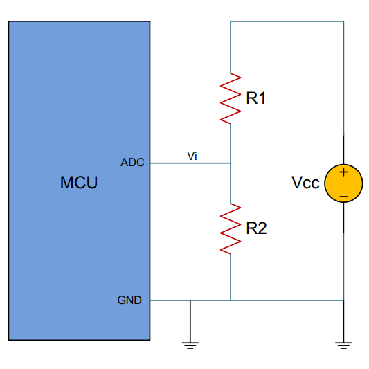
The classical way to measure a system’s voltage is to connect one of your MCU’s ADC pins to a voltage divider made from a couple resistors. A simple calculation yields a reading of the system’s voltage, but this approach has two disadvantages: one is that it constantly consumes power, and the other is that it ties up a pin that you might want to use for something else.
There are ways to mitigate these issues, but it would be best to avoid them entirely. Microchip application note 2447 describes a method of doing exactly that, and that’s precisely what [Trent]’s Arduino library implements.
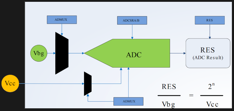
What happens in this method is one selects Vbg (a fixed internal voltage reference that is temperature-independent) as Vin, and selects Vcc as the ADC’s voltage reference. This is essentially backwards from how the ADC is normally used, but it requires no external hookup and is only a bit of calculation away from determining Vcc in millivolts. There is some non-linearity in the results, but for the purposes of measuring battery power in a system or deciding when to send a “low battery” signal, it’s an attractive solution.
Being an Arduino library, CPUVolt makes this idea very easy to use, but the concept and method is actually something we have seen before. If you’re interested in the low-level details, then check out our earlier coverage which goes into some detail on exactly what is going on, using an ATtiny84.