Posts with «arduino» label

Every jack-o’-lantern needs a pair of animatronic eyes

If you’d like your jack-o’-lantern to stand out, a pair of animatronic eyes should do the trick. While there are numerous ways that you can go about this, few (if any) look as good as the set made by Will Cogley in the first video below.

The incredibly realistic 3D-printed eyeballs are installed into the hollowed out pumpkin using skewers as supports, and glance in all directions, along with orange eyelids that open and close for an even more human(ish) appearance. 

The second clip delves deeper into the eyeballs themselves, which come in several forms. Control is via a Wii Nunchuk-esque joystick interface, with the help of an Arduino.

Pen plotter? Laser engraver? This DIY machine gives you both!

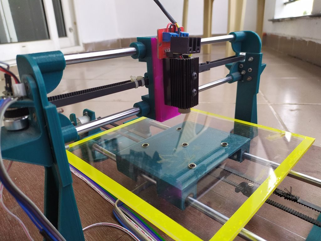
If you find yourself debating between a pen plotter or laser engraver, this project by Patrick Panikulam lets you have the best of both worlds in style. The DIY device pulls a writing instrument in the X-axis using a belt-driven overhead system, while the base itself moves in the Y direction.

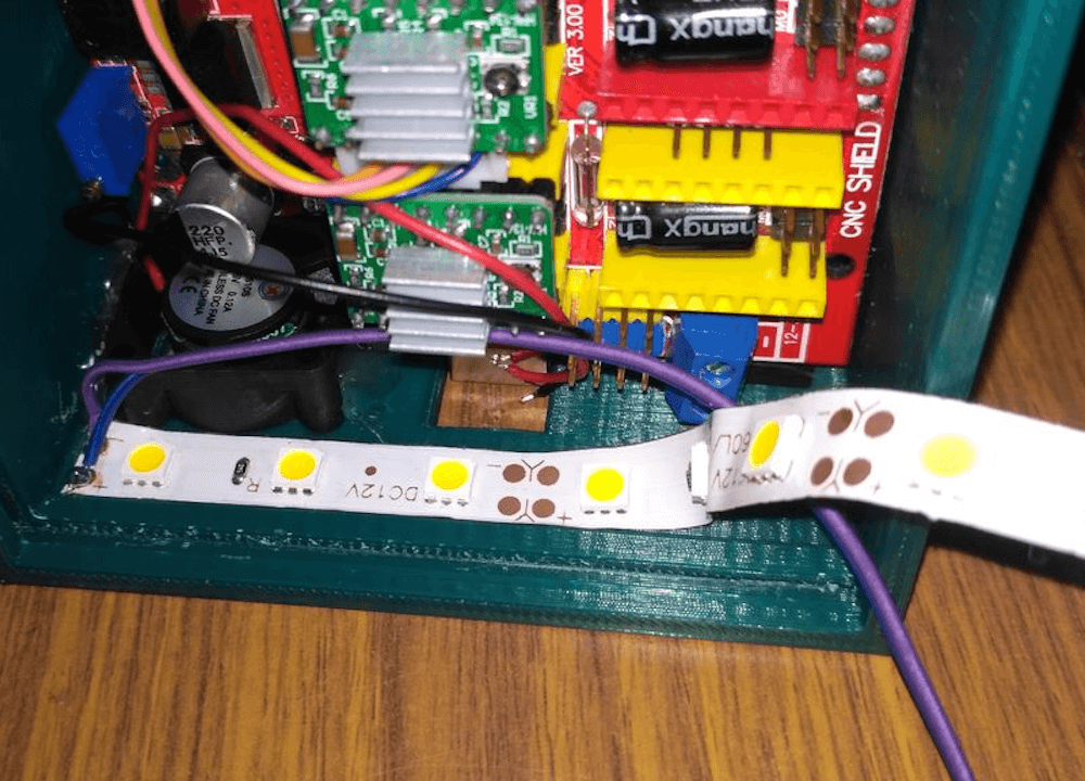
Motion is handled by an Arduino Uno, along with a CNC shield and two A4988 drivers that actuate modified 28BYJ-48 steppers. The shield also outputs laser control signals, which are converted into PWM signals for the lifting servo when in pen mode. 

It’s an extremely clean build, and even features a Bluetooth module for wireless communication with your computer. Panikulam provides more details here if you’d like to create your own!

A couple of months back while checking out a few laser engravers on aliexpress, I came across some USB powered laser engravers. It was awesome that these could engrave on a variety of materials and also cut out shapes and designs from sticker sheets and paper and doing all this powered by a 5V USB supply. But the downside of these engravers was that they had a small work area, in most cases just 40mm X 40mm which is definitely way too small for my needs.

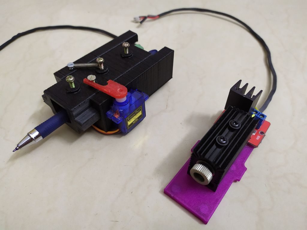
So I thought why not design and 3D print my own laser engraver from scratch. I started the designing process in Fusion 360 while keeping in mind all the 3D printing tolerances. And finally came up with something really cool. Along the way, I decided to make the laser holder modular so that I can easily replace the laser with a pen or marker for pen plotting. I also added a Bluetooth connectivity feature so that wired connection between your PC and the engraver can be eliminated while transmitting G-codes.

Godot Machine is the Project You’ve Been Waiting For

Are you waiting for something that may never happen? Maybe it’s the end of your ennui, or the release of Half Life 3. While you wait, why not build a Godot Machine? Then you can diversify your portfolio and wait for two things that could happen today, tomorrow, or at sunrise on the 12th of Never.

The Godot Machine is a functional art piece that uses a solar panel and a joule thief to charge a bank of capacitors up to 5V. Whenever that happens, the Arduino comes online and generates a 20-bit random number, which is displayed on an LED bar. If the generated number matches the super-secret number that was generated at first boot and then stashed away in EEPROM, the Machine emits a victory beep and lights a green LED. Then you can go back to complaining about whatever.

We like that [kajnjaps] made his own chaos-based random number generator instead of just calling random(). It uses a guitar string to collect ambient electronic noise and an entropy generator to amplify it. Then the four least significant digits are used to seed the logistical map, so the initial value is always different.

You don’t have to create your own entropy for truly random numbers, though it’s probably more fun that way. Did you know that someone wrote an Arduino entropy library?

Cisco switches converted into a cocktail machine

If you want to whip up a cocktail, you can measure out the components by hand, or you could use a robotic assistant like this setup by creator Sven Tantau.

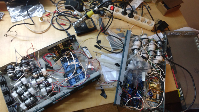
Tantau’s project employs an Arduino Nano to control 24 peristaltic pumps via a relay card, plus an ESP32 to run a web interface and send I2C commands to the Arduino letting it know which pumps to enable.  

The pumps, along with the relays and other components, are arranged inside the stripped shell of two Cisco Catalyst switches. In fact, the only electrical part from the router that’s still in use is the 12V power supply. 

This does, however, do a fantastic job of looking good while hiding the electronics inside, and transport tubing is nicely arranged on a 3D-printed grid where the Ethernet plugs once connected!

Arduino Blog 29 Oct 20:36

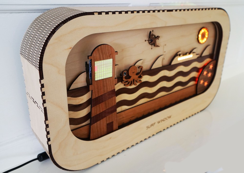
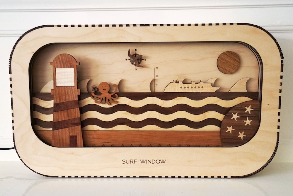
Surf Window is an interactive beach diorama that displays surf conditions

While some of us live directly beside the beach, others—the vast majority, in fact—reside inland where we can’t see the waves on a day-to-day basis. As a solution to this issue, surfer-maker Luke Clifford came up with his own “Surf Window,”an interactive diorama that shows real-time surf conditions at a glance.

The Arduino Mega-controlled device pulls beach info from the Magicseaweed API, then adjusts the laser-cut wooden stage to match. Indicators include starfish that light up depending on how good the surf conditions are overall, a physical wave model that moves up and down to represent height, a rotating seagull to reveal wind direction, and more. 

Whether you’re a landlocked surfer, or just someone who wants to know more about the environment, this looks like a really interesting gadget. The build is currently wrapping up a Kickstarter campaign if you’d like to have your own!

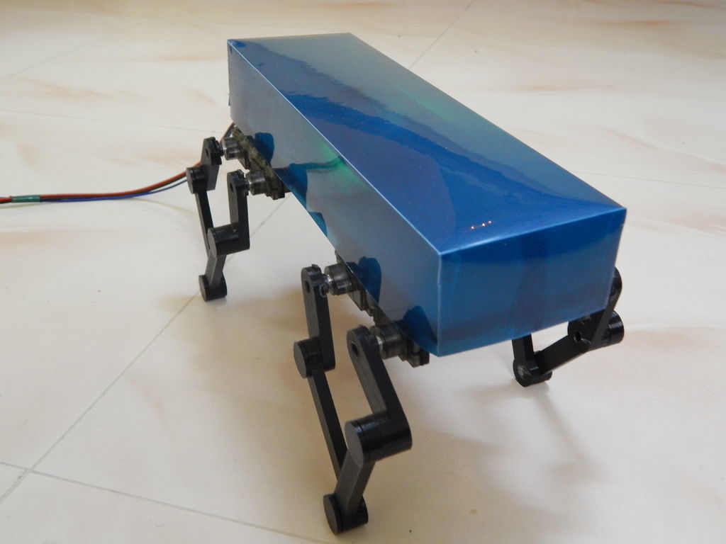
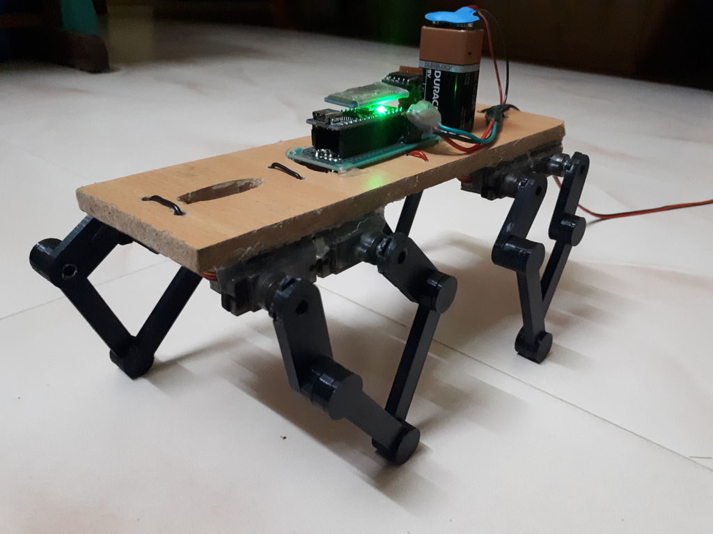
Baby Cheetah is a mini, MIT-inspired quadruped robot

Although we can’t all have the MIT Mini Cheetah at home, Jegatheesan Soundarapandian decided to make his own version — measuring just 23 cm x 9 cm x 9 cm.

As shown in the video below, the aptly named “Baby Cheetah” does an amazing job of getting around on four legs, and is not only able to walk upright, but can even move at a crouch, turn, and tilt forwards or backwards.

The robot is equipped with eight SG90 servos to actuate each 3D-printed leg linage assembly, giving the limbs excellent mobility in a vertical plane. An Arduino Nano is used for control, while an HC-05 Bluetooth module links to a smartphone running a custom app for user interface. 

More info and Arduino code is available in Soundarapandian’s project write-up.

Tutorial – Using the TCA9548A 1-to-8 I2C Multiplexer Breakout with Arduino

Now and again you may find yourself needing to use more than one device with the same I2C bus address with your Arduino.

Such as four OLEDs for a large display – or seven temperature sensors that are wired across a chicken hatchling coop.

These types of problems can be solved with the TCA9548A 1-to-8 I2C Multiplexer Breakout, and in this guide we’ll run through the how to make it happen with some example devices.

Getting Started

First, consider the TCA9548A itself. It is the gateway between your Arduino and eight separate I2C buses. You have a single bus on one side, connected to your Arduino.

On the other side of the TCA9548A, you have eight I2C buses, and only one of these can be connected to the Arduino at a time. For example (from the data sheet):

The TCA9548 can operate on voltages between 1.8 and 5V DC… and operate with devices that have operating voltages between 1.8 and 5V DC. This is very convenient, as (for example) you can use devices made for 3.3V operation with 5V Arduinos, or vice versa. Awesome. So let’s get started.

The breakout board includes inline header pins, which are not soldered to the board. So you need to do that. An easy way to line up the pins properly is to drop them into a soldereless breadboard, as such:
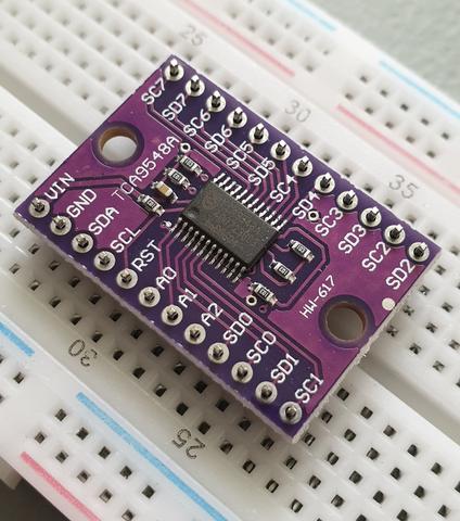
Then after a moment or two of soldering, you’re ready to use:
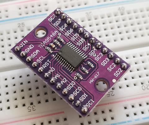
Next, insert your module into a solderless breadboard and wire it up as shown:

We are using the red and blue vertical strips on the breadboard as 5V and GND respectively. Finally, we connect the 5V and GND from the Arduino to the solderless breadboard, and A4/A5 to SDA/SCL respectively on the breakout board:
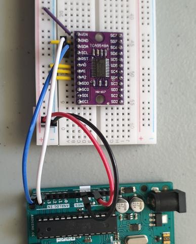
The electrical connections are as follows (Module — Arduino):

  • Vin to 5V
  • GND to GND
  • A0 to GND
  • A1 to GND
  • A2 to GND
  • SDA to A4
  • SCL to A5

Next, we consider the I2C bus address for the TCA9548A. Using the wiring setup shown above, the address is set to 0x70. You only need to change this if one of your other devices also has an address of 0x70, as shown in the next step.

Changing the I2C address of the TCA9548A

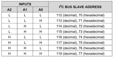
The bus address of the TCA9548A is changed using the connections to the A0, A1 and A2 pins. By default in the tutorial we use 0x70, by wiring A0~A2 to GND (known as LOW). Using the table below, you can reconfigure to an address between 0x70 and 0x77 by matching the inputs to HIGH (5V) or LOW (GND):
Testing 

Before we get too excited, now is a good time to test our wiring to ensure the Arduino can communicate with the TCA9548A. We’ll do this by running an I2C scanner sketch, which returns the bus address of a connected device.

Copy and paste this sketch into your Arduino IDE and upload it to your board. Then, open the serial monitor and set the data rate to 115200. You should be presented with something like the following:
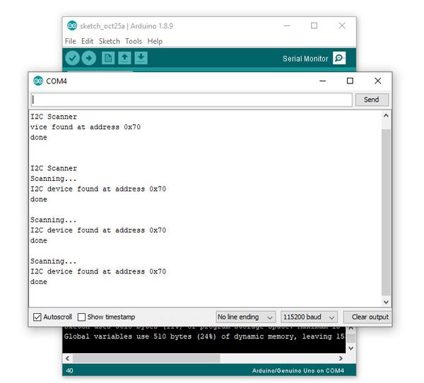
As you can see, our scanner returned an address of 0x70, which matches the wiring described in the bus address table mentioned earlier. If you did not find success, unplug the Arduino from the computer and double-check your wiring – then try again.

Controlling the bus selector

Using the TCA9548A is your sketch is not complex at all, it only requires one step before using your I2C device as normal. That extra step is to instruct the TCA9548A to use one of the eight buses that it controls.

To do this, we send a byte of data to the TCA9548A’s bus register which represents which of the eight buses we want to use. Each bit of the byte is used to turn the bus on or off, with the MSB (most significant bit) for bus 7, and the LSB (least significant bit) for bus 0.

For example, if you sent:

0b00000001 (in binary) or 0 in decimal

… this would activate bus zero.

Or if you sent:

0b00010000 (in binary)

… this would activate bus five.

Once you select a bus, the TCA9548A channels all data in and out of the bus to the Arduino on the selected bus. You only need to send the bus selection data when you want to change buses. We’ll demonstrate that later.

So to make life easier, we can use a little function to easily select the required bus:

void TCA9548A(uint8_t bus)
{
  Wire.beginTransmission(0x70);  // TCA9548A address is 0x70
  Wire.write(1 << bus);          // send byte to select bus
  Wire.endTransmission();
}

This function accepts a bus number and places a “1” in the TCA9548A’s bus register matching our requirements. Then, you simply slip this function right before needing to access a device on a particular I2C bus. For example, a device on bus 0:

TCA9548A(0);

… or a device on bus 6:

TCA9548A(6);

A quick note about pull-up resistors

You still need to use pull-up resistors on the eight I2C buses eminating from the TCA9548A. If you’re using an assembled module, such as our example devices – they will have the resistors – so don’t panic.

If not, check the data sheets for your devices to determine the appropriate pull-up resistors value. If this information isn’t available, try 10k0 resistors.

Controlling our first device

Our first example device is the tiny 0.49″ OLED display. It is has four connections, which are wired as follows (OLED — TCA9548A/Arduino):

  • GND to GND
  • Vcc to Arduino 3.3V
  • CL to TCA9548A SC0 (bus #0, clock pin)
  • DA to TCA9548A SD1 (bus #0, data pin)

The OLED runs from 3.3V, so that’s why we’re powering it directly from the Arduino’s 3.3V pin.

Now, copy and upload this sketch to your Arduino, and after a moment the OLED will display some numbers counting down in various amounts:

So how did that work? We inserted out bus selection function at line 9 of the sketch, then called the function in at line 26 to tell the TCA9548A that we wanted to use I2C bus zero. Then the rest of the sketch used the OLED as normal.

Controlling two devices

Let’s add another device, a BMP180 barometric pressure sensor module. We’ll connect this to I2C bus number seven on the TCA5948A. There are four connections, which are wired as follows (BMP180 — TCA9548A/Arduino):

  • GND to GND
  • Vcc to Arduino 3.3V
  • CL to TCA9548A SC0 (bus #7, clock pin)
  • DA to TCA9548A SD1 (bus #7, data pin)

Now, copy and upload this sketch to the Arduino, and after a moment the OLED will display the ambient temperature from the BMP180 in whole degrees Celsius. This is demonstrated in the following video (finger is placed on the BMP180 for force a rise in temperature):

So how did that work? We set up the libraries and required code for the OLED, BMP180 and TCA5948A as usual.

We need to intialise the BMP180, so this is done at line 29 – where we select the I2C bus 7 before initiating the BMP180.

The the sketch operates. On line 40 we again request I2C bus 7 from the TCA9548A, then get the temperature from the BMP180.

On line 44 we request I2C bus 0 from the TCA9548A, and then display the temperature on the OLED. Then repeat.

A quick note about the reset pin

More advanced users will be happy to know they can reset the TCA9548A status, to recover from a bus-fault condition. To do this, simply drop the RESET pin LOW (that is, connect it to GND).

Where to from here? 

You can now understand through our worked example how easy it is to use the TCA9548A and access eight secondary I2C buses through the one bus from your Arduino. Don’t forget that the TCA9548A also does double-duty as a level converter, thereby increasing its value to you.

And that’s all for now. This post brought to you by pmdway.com – everything for makers and electronics enthusiasts, with free delivery worldwide.

To keep up to date with new posts at tronixstuff.com, please subscribe to the mailing list in the box on the right, or follow us on twitter @tronixstuff.

Tronixstuff 29 Oct 04:57

Arduino IoT Cloud: Support for ESP8266 and other third party boards

With the latest release of Arduino IoT Cloud (version 0.8.0) we did a lot of work behind the scenes, and while it might be transparent to most users, it introduced some big changes. But the one we’re most excited about is that the Arduino IoT Cloud has begun supporting a number of third party devices.

Starting with the uber-popular ESP8266 by Espressif — NodeMCU, Sparkfun’s ESP Thing, ESPDuino, and Wemos (to name a few) — along with other inexpensive commercially available plugs and switches based on this module. You can now add one to your Cloud Thing and control it using our intuitive web-based Dashboard.

Like every new release, there were plenty of obstacles to get around, especially providing security between the third party boards and the  Arduino IoT Cloud, where there’s no possibility to go through our secure certificate provisioning process because the hardware is lacking an essential component: the cryptographic element.

The Arduino IoT Cloud was born with security in mind and developed around the Arduino MKR series of boards featuring Microchip’s ATTECx08, an encryption chip capable of elliptic-curve cryptography. These boards store the bits necessary to authenticate with a server in a very secure way, guaranteeing your board is connecting to the real server and exchanging data over TLS.

When it comes to boards that don’t have enough RAM and do not feature such cryptographic elements, we had to enable a secondary way to get in. Data transfer will still be encrypted over SSL, but the server authentication part will be a little less strict, allowing the Arduino IoT Cloud to be available to a wider user base. Nevertheless, we do inform users that if they want the highest levels of security they’ll have to use a board which embeds a cryptographic chip. As more and more IoT device users become concerned with security, manufacturers are starting to implement such technologies. We have just recently seen standalone ECC modules which can be paired with your microcontroller of choice. It’s looking bright, and we’re proud to have been amongst the first to bring about this change.

For third party boards without a crypto chip, we had to extend our API and allow the creation of a device-exclusive unique identifier (which will be used as a username) and the generation of a Device Key, providing the final user to access the platform using a username: password pair. 

Internally we already used those tools and APIs; we’re just opening them up for use by a broader audience.

One small requirement for this to work is that you’ll need to upgrade your Arduino Create plan to the ‘Maker plan.’ This will give you access to ESP8266 compilation and IoT Cloud pairing of the device. The Maker plan will also extend the amount of original Arduino boards and Things you can create and manage.

This is just the first step in opening up to more and more hardware, and we have a lot of things lined up for our users. We really hope you’ll enjoy the ease of development and the tools to bring your application to the Cloud in the shortest possible time.

Head over to Arduino IoT Cloud and show us what you got!

Sixi 2, An Open Source 3D Printable 6 Axis Robot Arm

[Dan Royer] is taking some inspiration from Prusa’s business and is trying to build the same sort of enterprise around open source 3D printable robot arms. His 6 axis robot arm is certainly a strong first step on that road. 

As many people have learned, DIY robot arms are pretty difficult.  [Dan]’s arm has the additional complexity of being 3D printable with the ambitious goal of managing a 2kg payload at 840mm of reach. He’s already made significant progress. There’s a firmware, set of custom electronics, and a Fusion 360 project anyone can download and checkout. You can even control it with an Xbox controller.

The main board is an Arduino shield which outputs step and direction signals to stepper drivers. The gears are cycloidal and it appears there’s even some custom machining going on. When the parts are all laid out it becomes clear just how much effort has been put into this design.

It should be a pretty nice robot and might finally spur some of us to build the Iron Man style robot assistants we’ve always wanted. You can see the robot in action after the break.

The HackadayPrize2019 is Sponsored by:

Electricity Makes Soft Robotics More Like Us Meatbags

Building a future where robots work alongside humans relies heavily on soft robotics. Typically this means there will be an air compressor or a hydraulic system nearby, taking up precious space. But it doesn’t have to.

Engineers at the UC-San Diego Jacobs School have created a soft robotics system that uses electricity to control flexible actuators, much like our brains move our muscles. It works like this: sheets of heat-sensitive liquid crystal elastomer are sandwiched between two layers of standard elastomer. These layers are rolled into cylinders that can twist and bend in different directions depending on which of its six element(s) get electricity. Light up all six, and the tube contracts, forming the foundation for a good gripper. The team also built a tiny walker, pictured above.

The project is still in its infancy, so the actuators are slow to bend and even slower to return to their original shape, but it’s still a great start. Imagine all the soft robotic projects that can get off the ground without being shackled by the bulk and weight of an air compressor or fluid handling system. Watch it do various sped-up things after the break, like claw-machine gripping a bottle of chocolate rocks.

Speaking of delicious candy, edible soft robotics is totally a thing.

Via Arduino blog