Hands on with the Light Blue Bean
 We took an initial look at Punch Through Design's Light Blue Bean when they opened for pre-orders. Now we have our hands on the hardware it's time to take a closer look.

 We took an initial look at Punch Through Design's Light Blue Bean when they opened for pre-orders. Now we have our hands on the hardware it's time to take a closer look.
It’s time to announce a new partner in the Arduino At Heart program!
Nix, The Diamond Standard In Color Measurement, is a unique device capable of determining the exact color of any object or surface in RGB, CMYK, HTML, Lab, and even specific paint from your favorite brand. Imagine a Photoshop eyedropper in real life: Nix is a small, durable, buttonless tool that can easily fit in your pocket or bag.

It’s a useful device especially for graphic designers, interior designers, artists, photographers, hobbyists, anyone who wants to become a colour expert. It utilizes Bluetooth 4.0 technology to display the exact color on your iOS or Android device. Once scanned, you can keep palettes of your favorite colors, match the color to real life pigments, and even receive directions to the nearest store where you can purchase the color.
On top of that Nix is ultra hackable. You can easily reprogram it with all the familiar tools available in the Arduino IDE.
Take a look at their successful kickstarter campaign page and at the video below to learn more :
Nix Color Sensor is designed and assembled in Hamilton, Ontario, Canada by Nix Sensor Ltd and its CEO Matt Sheridan (info@nixsensor.com) is available to answer all your questions. If you want to make it yours, visit the webesite nixsensor.com .

To celebrate America’s students and entrepreneurs who are inventing the future with new technologies and techniques, today the President Of United States, Barack Obama is hosting the first-ever White House Maker Faire , and has proclaimed June 18 as National Day of Making. The event is featuring Makers, innovators, and entrepreneurs of all ages who are using cutting-edge tools to bring their ideas to life.

We are also happy to announce that Arduino was invited to participate and Massimo Banzi is right now in Washington.
Follow the streaming in the video below! More news soon!
Our friends at Temboo are releasing more cool stuff for your Internet of Everything. Here’s some news from their blog.
———————————-
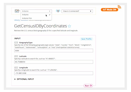
Now you can connect even more Arduinos with the power of Temboo by simply flipping our IoT Mode on. This new feature opens up a whole new world of possibilities for the Internet of Things.
What is IoT mode, you ask?
It’s a new way to access our 2,000+ Choreos on any of your Arduino or Arduino-compatible boards. By just hitting a switch at the top right of any Choreo page, you “got the power” to call that Choreo with a sketch tailored specifically for the device you pick from our drop down menu. Previously, this feature was only available for the Yún, but now it is open to the larger Arduino family. All you have to do is select the type of shield your board uses and the code will generate accordingly.
So how do I begin using this amazing IoT feature?
Select a Choreo from our vast Library and turn on IoT Mode. In the example below, we chose the Data.gov API and the GetCensusIdByCoordinates Choreo. Data.gov is a cool way to access APIs from a number of US governmet agencies and to query government datasets, including the US Census!
The “Arduino” option encompasses compatible boards that lack the Yún’s built-in wifi capabilities, but can connect to the internet with a shield. Fill out your shield’s specifics when the popup appears and save for future use. Run your Choreo and scroll down to retrieve the code for the sketch, ready to be pasted into your Arduino IDE. You can even plug this into a sketch generated by our nifty Device Coder to start mixing and matching!
We are thrilled just thinking of all of the possibilities this unlocks for the Internet of Things. We want to hear all about what you cook up with this new capability, so if you are working on an interesting project, reach out to us at hey@temboo.com!
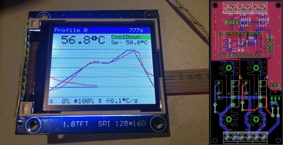
A reflow oven is one of the most useful tools you will ever have, and if you haven’t built one yet, now is as good a time as any. [0xPIT's] Arduino based reflow oven controller with a graphic LCD is one of the nicest reflow controllers we’ve seen.
Having a reflow oven opens up a world of possibilities. All of those impossible to solder surface mount devices are now easier than ever. Built around the Arduino Pro Micro and an Adafruit TFT color LCD, this project is very straight forward. You can either make your own controller PCB, or use [0xPIT's] design. His design is built around two solid state relays, one for the heating elements and one for the convection fan. “The software uses PID control of the heater and fan output for improved temperature stability.” The project write-up is also on github, so be sure to scroll down and take a look at the README.
All you need to do is build any of the laser cutters and pick and place machines that we have featured over the years, and you too can have a complete surface mount assembly line!


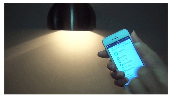
We’re happy to share with you the update of the Indiegogo campaign of the Arduino At Heart for home automation we presented some time ago. Ez Control goes wireless!
———————————–
We have been silent for most of the time of this campaign, but this doesn’t means that we were sleeping. Not at all!
We were listening and interacting. We have received your comments, we have followed the topic on Reddit, we have exchanged ideas with many of you and we spent all this time improving our product.
Some of you was concerned about the relay, maybe too small. Some other concern was related to the position of the temperature sensor, that could offer false reading caused by the heat from other components.
We have upgraded the relay with a new one, rated 5A, and we have also improved the physical insulation for the high voltage circuit. We have then improved the insulation of the temperature sensor.
Sure all interesting, but those where not the main doubts about our hardware.
The most requested upgrade was related to the connectivity.
Why in 2014 do we use wires?
We admit that going wireless it was in our plans for the future. We wanted to start with an easy to use board, affordable and based on well known technologies, open to most of the users.
Reading and listening all your comments, we have understood that we should change our plan, and we did it.
Yes! We spent the past month with design, engineering, prototyping and testing of the brand new and immediately available EZboard WiFi!
This means that every perk and everyone will receive NOT the old board based on the cables and 10Mbit Ethernet controller, but this new, fantastic, WiFi development board.
And the price will not change!!!
Andrea & the EZBoard team
————–
 Getting started using Bluetooth LE is much harder than it should be, and that a lot of great work people are doing is getting dropped on the floor, or worse yet done again. We decided to sit down and do something about that.
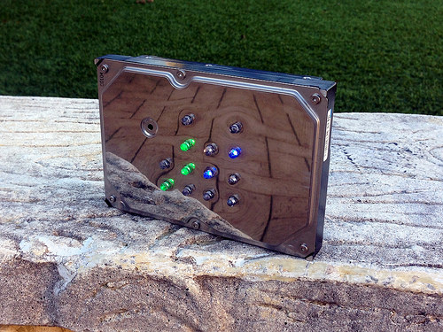
[Aaron] has been wanting to build his own binary desk clock for a while now. This was his first clock project, so he decided to keep it simple and have it simply display the time. No alarms, bells, or whistles.
The electronics are relatively simple. [Aaron] decided to use on of the ATMega328 chips he had lying around that already had the Arduino boot loader burned into them. He first built his own Arduino board on a breadboard and then re-built it on a piece of protoboard as a more permanent solution. The Arduino gets the time from a real-time clock (RTC) module and then displays it using an array of blue and green LED’s. The whole thing is powered using a spare 9V wall wort power supply.
[Aaron] chose to use the DS1307 RTC module to keep time. This will ensure that the time is kept accurately over along period of time. The RTC module has its own built-in battery, which means that if [Aaron's] clock should ever lose power the clock will still remember the time. The RTC battery can theoretically last for up to ten years.
[Aaron] got creative for his clock enclosure, upcycling an old hard drive. All of the hard drive guts were removed and replaced with his own electronics. The front cover had 13 holes drilled out for the LED’s. There are six green LED’s to display the hour, and seven blue LED’s for the minute. The LED’s were wired up as common cathode. Since the hard drive cover is conductive, [Aaron] covered both sides of his circuit board with electrical tape and hot glue to prevent any short circuits. The end result is an elegant binary clock that any geek would be proud of.


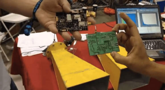 The very first fully operational radar Arduino shield was recently demonstrated at Bay area Maker Faire. It was built by [Daniel] and [David], both undergrads at UC Davis.
Many have talked about doing this, some have even prototyped pieces of it, but these undergrad college students pulled it off. This is the result from Prof. ‘Leo’ Liu’s full-semester senior design course based on the MIT Coffee Can radar short course, which has been going on for 2 years now. Next year this course will have 30 students, showing the world the interest and market-for project based learning. yet again showingWe the influence of hackers on higher education.
Check out the high res ranging demo, where a wider band chirp was used to amazing results. Video below.


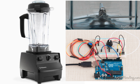 Some people really love their smoothies. We mean really, really, love smoothies and everything about making them, especially the blenders. [Adam] is a big fan of blenders, and wanted to verify that his Vitamix blenders ran as fast as the manufacturer claimed. So he built not one, but two speed measuring setups. Scientific blender measurement method requires one to cross check their results to be sure, right?
Measuring the speed of a blender is all about the RPM. Appropriately, [Adam's] first measurement tool was an LED based stroboscope. Stroboscopes have been around for hundreds of years, and are a great way to measure how fast an object is rotating. Just adjust the speed of a flashing light until the rotating object appears frozen. The number of blinks per second is then equal to the Rotations Per Second (RPS) of the object being measured.Multiply by 60 seconds, and you’ve got RPM. [Adam] used an Arduino as the brains behind his stroboscope. He wired a dial up on his breadboard, and used it to adjust the flash rate of an LED. Since this was a quick hack, [Adam] skipped the display and just used the Arduino’s USB output to display speed measurements on his laptop.
There are possibilities for error with stroboscopes. [Adam] discovered that if the stroboscope was flashing at a multiple of the blade’s rotation speed, the blades would appear frozen, and he’d get an erroneous RPM value. Thankfully, [Adam's] Vitamix had asymmetric blades, which made the test a bit easier. He calculated his blades to be spinning at 380 RPS, or 23,000 RPM. Not satisfied with his results, [Adam] brought out Audacity, and ran a spectral analysis of the blender in operation. He found a peak at 378Hz, which was pretty darn close to his previous measurement. Since the blender has a 4 inch blade this all works out to a blade tip speed right around the claimed value of 270 MPH. We’re glad [Adam] found an answer to his blender questions, but our personal favorite blender hack still has to be the V8 blender created by the Top Gear crew. [via HackerNews]

