Posts with «arduino» label

3D Print Your Own Stepper Motor

Learn how one Maker created his own stepper motor using a 3D printer, an Arduino, and a few materials picked up from the hardware store.

Read more on MAKE

The post 3D Print Your Own Stepper Motor appeared first on Make: DIY Projects, How-Tos, Electronics, Crafts and Ideas for Makers.

Hackaday Prize Entry: Project Dekoboko 凸凹 Maps Bumpy Roads On A Bike

If you live in New England (like me) you know that the roads take a pounding in the winter. Combine this with haphazard maintenance and you get a recipe for biking disaster: bumpy, potholed roads that can send you flying over the handlebars. Project Dekoboko 凸凹 aims to help a little with this, by helping you map and avoid the bumpiest roads and could be a godsend in this area.

The 2015 Hackaday Prize entry from [Benjamin Shih], [Daniel Rojas], and [Maxim Lapis] is a device that clips onto your bike and maps how bumpy the ride is as you pedal around. It does this by measuring the vibration of the bike frame with an accelerometer. Combine this with a GPS log and you get a map of the quality of the roads that helps you plan a smooth ride, or which could help the city figure out which roads need fixing the most.

The project is currently on its  third version, built around an Arduino, Adafruit Ultimate GPS Logger shield, and a protoboard that holds the accelerometer (an Analog ADXL345). The team has also set up a first version of their web site, which contains live data from a few trips around Berlin. This does show one of the issues they will need to figure out, though: the GPS data has them widely veering off the road, which means that the data was slightly off, or they were cycling through buildings on the Prinzenstrasse, including a house music club. I’ll assume that it was the GPS being inaccurate and not them stopping for a rave, but they will need to figure out ways to tie this data down to a specific street before they can start really analyzing it. Google Maps does offer a way to do this, but it is not always accurate, especially on city streets. Still, the project has made good progress and could be useful for those who are looking for a smooth ride around town.

The 2015 Hackaday Prize is sponsored by:


Filed under: The Hackaday Prize, transportation hacks

New Project: Build an Automatic Photo Rig for Perfect Panoramas

Make an automatic camera rig for shooting high-resolution panoramas with a point-and-shoot camera.

Read more on MAKE

The post Build an Automatic Photo Rig for Perfect Panoramas appeared first on Make: DIY Projects, How-Tos, Electronics, Crafts and Ideas for Makers.

You Can Have my TIPs When You Pry them from my Cold, Dead Hands

We’ve seen a growing number of posts and recommendations around the net regarding components, specifically transistors. “Don’t use old parts” they cry,  “Go with newer components.”  You can often find these recommendations on Arduino forums. This all came to a head with a page called “Do Not TIP,” which was linked in the Arduino subreddit.  This page belongs to [Tom Jennings], creator of Fidonet, and one of the early authors of what would become Phoenix BIOS. [Tom] and a few others have been calling for everyone to send their old parts to the landfill – not use them, nor gift them to new experimenters. Get them out of the food chain. No offense to [Tom], but we have to disagree. These parts are still perfectly usable for experienced designers, and have a lot to offer new hardware hackers.

TIP is the part number prefix for a series of power transistors created by Texas Instruments.  In fact, “TIP” stands for Texas Instruments Power. The series was originally released in 1969. Yes, that’s right, 1969. Why are we still using parts designed when man first walked on the moon? The same reason people are still using the 555 timer: they’re simple, they’re easily available, they’re robust, and most of all, they get the job done. The TIP series has been used in thousands of classes, tutorials both online and off, and millions of projects over the years. Much of that documentation is already out there on the internet. The TIP series is also out in the distribution channel – they’ve been used for 40 years. Any retail shop that stocks a few electronics parts will have at least one of the TIP series.

The TIP series aren’t always the best transistors for the job. However, for most hobbyist-designed circuits, we don’t need the best performance, nor the best price – we’re going to use the parts we have on hand. There is always room to improve once you get the basic circuit working.  

In [Tom’s] specific example, he’s using a TIP120 to control a motor at 5 volts drawing 1 amp of current. [Tom’s] big problem with the TIP120 is that it’s inefficient when running the motor. That’s because the TIP120 isn’t a transistor. It’s two transistors configured as a Darlington pair. Like everything else in life, Darlington pairs have trade offs. To achieve high gain, you end up with higher voltage drop. In high current designs, that translates into heat. In this case, 2 watts of heat, which [Tom] claims will result in melted parts and fire. It turns out that the datasheet shows 2 watts is the upper limit for thermal dissipation on the TIP120’s TO-220 case. It will get very hot, but it will not catch fire. Want to be on the safe side? Add a heatsink, which is as easy as attaching a piece of metal using the convenient screw hole in the TO-220 case.

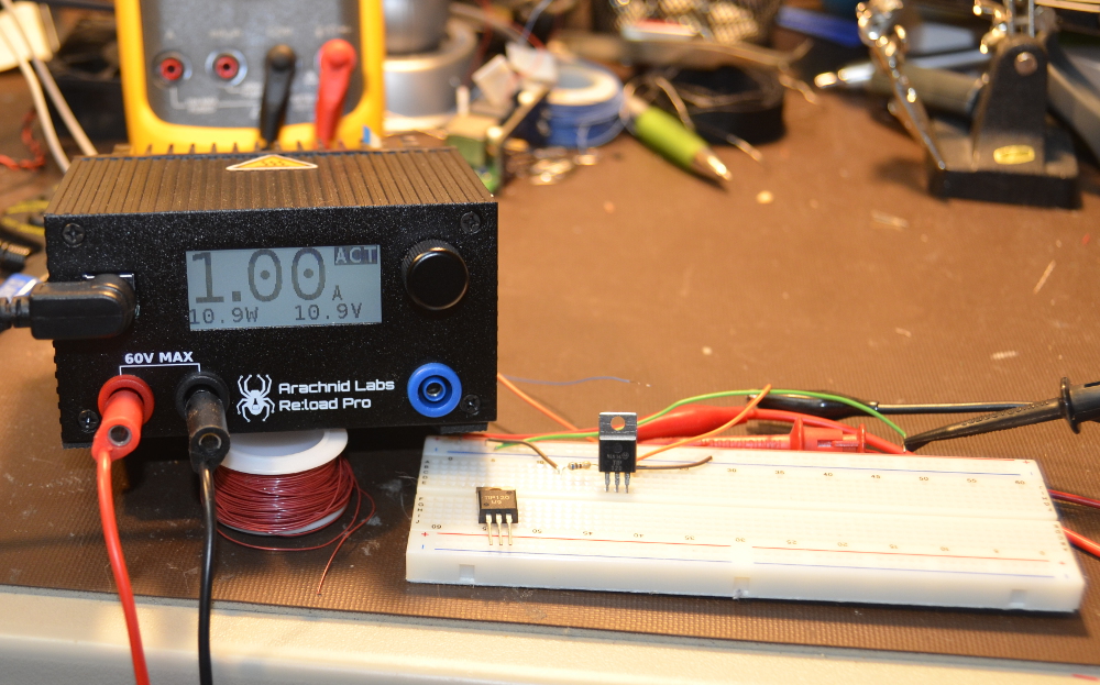
Just for fun, we created our own version of [Tom’s] example. We connected a TIP120 to a 12V lab supply. Rather than connect a motor, we grabbed our Re:Load Pro and set it for 1 amp. We use a 680 ohm base resistor to ensure the TIP120 was in saturation. The Re:Load Pro indicated that it was indeed seeing 1 amp of current flow, at 10.9 volts. This means that the TIP120 was only dropping 1.1V, rather than the 2V quoted on the datasheet. Were we just lucky? We tried a few TIP120s we had around the lab from a couple of manufacturers, and all of them were pretty close – well below the worst case 2V. Obviously you can’t design beyond the specs called on in the datasheet, but sometimes things work out in your favor. With the current set to 1 amp, the math is easy. The Re:Load Pro was converting 10.9 watts of power to heat. The TIP120 was dissipating 1.1 watts. The TIP120 did get hot – we measured up to 60°C. But it never went beyond that. A heatsink would have cooled things down, but we were shooting for worst case scenario.  We ran this setup for 2 hours and there was no smoke, fire, or failure.

Can you do better with a different part? Absolutely. [Tom] suggests a MOSFET such as the NTD4906N. FETs are great, we use them all the time. However, they come with a completely different set of rules and pitfalls compared to BJTs. Learning the rules, the design trade offs and pitfalls of both families of devices are key factors when learning electronics design. Every component a designer learns is a new color on their design palette. On the code side we worry about people becoming “cut and paste” coders. The same thing happens on the hardware side when a designer doesn’t learn how to use different types of parts.

So don’t throw away your old parts. Use them, learn from them, and become a better designer for it!


Filed under: classic hacks, misc hacks

Beautiful Arduino Fireworks Controller

A lot of designers have the luxury of creating things that aren’t supposed to explode. That’s usually easy. The trick is designing things that are supposed to explode and then making absolutely sure they explode at the right time (and only the right time). [JonBush] recently did a beautiful build of an Arduino-based fireworks controller. Seriously, it looks like a movie prop from a summer blockbuster where [Bruce Willis] is trying to decide what wire to cut.

[Jon] used a mega 2560 because he wanted to do the I/O directly from the device. His code only takes about 8K of the total program storage, so with some I/O expansion (like shift registers) a smaller chip would do the job. The device can control up to 8 sets of fireworks, uses a physical arm key, and has a handheld remote. It is even smart enough to sense igniter failures.

The front panel is a work of art and includes a seven-segment display made from Neopixel LEDs. The whole thing is in a waterproof case and uses optical isolation in several key areas.

Fireworks are dangerous, so we might have designed in some more electronic safety features. For example, the power switch only interrupts the ground. It might be safer to disconnect both battery legs when off which would make it hard for a short to accidentally power the device. On commercial devices that explode, you’d probably see dual inputs so that a stuck switch causes a failure (that is, arming or firing requires one switch contact on and another off). The same for outputs. Driving the firing relays on both sides makes it harder for a stuck output to fire accidentally. Still, using a box like this is probably safer than a lit punk, so for this application, it is probably safe enough.

We’ve seen a lot of fireworks controllers in the past, but few of them have looked this good physically. We expect to see a copy of this in some movie next summer.


Filed under: Arduino Hacks

Hackaday Prize Entry: Nuclear Powered Random Number Generator

Random number generators come in all shapes and sizes. Some are software based while others, known as true random number generators, are hardware based. These can be created from thermal noise, the photoelectric effect and other methods. But none of these were good enough for [M.daSilva]. He would base his off of the radioactive decay of Uranium 238, and construct a working nuclear powered random number generator.

Because radioactive decay is unpredictable by nature, it makes for an excellent source for truly random data. The process is fairly simple. A piece of old fiestaware plate is used for the radioactive source. Put it in a lead enclosure along with a Geiger tube. Then wire in some pulse shaping circuitry and a microcontroller to count the alpha particles. And that’s about it. [M.daSilva] still has to do some statistical analysis to ensure the numbers are truly random, along with making a nice case for his project. But all in all, it seems to be working quite well.

Be sure to check out the video for quick rundown of [M.daSilva’s] project. If randomness is your thing, make sure you check out entropy harvested from uninitialized RAM, and the story behind the NIST randomness beacon.

The 2015 Hackaday Prize is sponsored by:


Filed under: Arduino Hacks

Hand Controlled Robot uses Accelerometer

What do orchestra conductors, wizards, and Leap controller users have in common? They all control things by just waving their hands. [Saddam] must have wanted the same effect, so he created a robot that he controls over wireless using hand gestures.

An accelerometer reads hand motions and sends them via an RF module to an Arduino. This is a bit of a trick, because the device produces an analog value and [Saddam] uses some comparators to digitize the signal for the RF transmitter. There is no Arduino or other CPU on the transmit side (other than whatever is in the RF module).

From the video, it looks like a natural way to control a robot as long as you don’t mind duct taping the transmitter to your hand. Of course, if you are a real hacking geek, you might even consider that an advantage as you can pretend you are working on becoming a cyborg.

[Saddam] spends some time talking about how the accelerometer works internally, and we’ve covered that before if you are curious. It turns out the devices aren’t as much electronic as we usually think of them, but mechanical.


Filed under: Android Hacks, robots hacks

Arduino-compatible software for FRDM-KL25Z board

As many of you have realized, I’m finding that doing multiple-platform support for the PteroDAQ system is a bit annoying.  One irritation is that the mbed.org compiler for the FRDM-KL25Z board is not integrated with the other compilers—not even sharing the same file system.  So every time I make a change, I need to transfer all the files between my laptop and the mbed website—I can’t use mercurial or git to keep things in sync.

All the other boards I’m using can be compiled for locally and downloaded to with the Arduino IDE.  It is not a particularly powerful IDE, but it is dead simple to use, and it runs on my old Mac OS 10.6.8 (at least, if I use Arduino 1.0.6—the newer versions seem to assume new Macs).  A lot of the “professional” IDEs assume that you replace your computer every year and have the latest OS installed, or that you use nothing but Windows.

Since the FRDM KL25Z board is currently one of the best price/feature microcontroller boards on the market, I figured that someone must be working on an Arduino plug-in for the hobbyist market.  So I did some Google searches and found something that initially looked promising: Arduino-compatible software library for FRDM-KL25Z board – CodeProject.

FRDM-KL25Z is an interesting ultra low cost board with 32-bit microcontroller. What makes it interesting for the Do-It-Yourself community is low price (about $13) and also the compatibility with the Arduino pinout. If you are Arduino user like me, you will probably also feel interest if you hear about a board which could, for less than half the price of standard Arduino board, give you a 32-bit ARM MCU running at 48 MHz with 128 KB of FLASH and 16 KB of RAM memory, on-board accelerometer and more. But as you might have expected, there is a “catch”. The  FRDM board has the same layout of pins, so you can connect the Arduino shields to it, but there is no software compatibility. You cannot use the Arduino API functions such as digitalRead, delay, etc. and you cannot program the board from the Arduino IDE. I was thinking it would be nice if you could… And this article is my first step in this direction.

Digging deeper, though, disappointed me.  They are trying to provide the trivial parts of the Arduino API, but they do their compiling with Kinetis Design Studio (which doesn’t run on Mac OS 10.6.8, and which is supposedly a bit of a bear to learn to use).  I’m more interested in the opposite combination—using the Arduino IDE, with only minimal use of the Arduino API (which I find a bit too inefficient for my tastes), except for a couple of difficult things (like the USB stack).

They’ve also licensed their code with a contagious LGPL license, which is too restrictive for the PteroDAQ code.

What I’m looking for is something like the Teensyduino implementation, but for the FRDM KL25Z board. I’ll have to look at how the Teensy loader is integrated into the Arduino IDE—if I can figure out how to put in copying a .bin or .s19 file to an emulated flash drive instead, then I can probably program for the KL26Z board, and possibly for the KL25Z board.


Filed under: Circuits course Tagged: Arduino, KL25Z, KL26Z, PteroDAQ, Teensy

Tiny Robot Shakes Head At You In Dissaproval

If you don’t have enough things staring at you and shaking their head in frustration, [Sheerforce] has a neat project for you. It’s a small Arduino-powered robot that uses an ultrasonic distance finder to keep pointing towards the closest thing it can find. Generally, that would be you.

When it finds something, it tries to track it by constantly rotating the distance finder slightly and retesting the distance, giving the impression of constantly shaking its head at you in disappointment. This ensures that you will either unplug it or smash it with a hammer after a very short time, but you should read [Sheerforce]’s code first: it’s a great example of documenting this for experimenters who want to build something that offers more affirmations of your life choices.


Filed under: Arduino Hacks
Hack a Day 16 Aug 00:01

Arduino Radar Watches You Breathe

We’ve all likely watched an episode of “Star Trek” and admired the level of integration on the sick bay diagnostic bed. With its suite of wireless sensors and flat panel display, even the 1960s imagining of the future blows away the decidedly wired experience of a modern day ICU stay. But we may be getting closer to [Dr. McCoy]’s experience with this radar-based respiration detector.

[Øyvind]’s build, which takes the origin of the term “breadboard” to heart, is based on a not-inexpensive Xethru module, which appears to be purpose-built for detecting respiration. The extra-thick PC board seems to house the waveguides internally, which is a neat trick but might limit how the module can be deployed. The module requires both a USB interface and level shifter to interface the 2.8V levels of the module to the 5V Arduino Uno. In the video below, [Øyvind]’s prototype simply lights an RGB LED in response to the chest movement it detects, but there’s plenty of potential for development here. We’ve seen a laser-based baby breathing monitor before; perhaps this systems could be used to the same end without the risk of blinding your tyke. Or perhaps better diagnostics for sleep apnea patients than an intrusive night in a sleep study lab.

Clocking in at $750USD for the sensor board and USB interface, this build is not exactly for the faint of heart or the light of wallet. But as an off-the-shelf solution to a specific need that also has a fair bit of hacking potential, it may be just the thing for someone. Of course if radar is your thing, you might rather go big and build something that can see through walls.


Filed under: Arduino Hacks, Medical hacks