Automatic Phone Dialer Illuminates Inner Workings
The invention of the transistor ushered in a lot of technologies that we now take for granted, and one of the less-thought-about areas that it improved living conditions worldwide was by making the touch-tone phone possible. No longer would the world have to fuss with dials to make phone calls, they could simply push some buttons. This technology is still in use today, and it is possible to build external phone dialers that use these tones to make phone calls, as [SunFounder] demonstrates with his latest project.
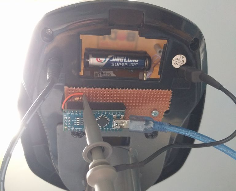
The tones that a phone makes when a button is pressed correlate with specific frequencies for each number. Automatic dialers like this one help when there are multiple carriers (like different long-distance carriers, for example) where different prefixes can be used to make calls cheaper depending on the destination of the call. A preprogrammed dialer can take all of this complication out of making phone calls. [SunFounder] is able to make a simple dialer from scratch, using an Arduino, its “tone” library, and a speaker that is simply held up to the phone that the call will be placed on.
[SunFounder] points out that he built this more because he’s interested in the inner workings of phones, and not because he needed a purpose-built dialer. It’s a good demonstration of how phones continue to use DTMF though, and how easy it is to interface with such a system. It might also suit a beginner as an introduction to the world of phreaking.
Filed under: phone hacks