Posts with «arduino» label

Hackaday Prize Entry: Smart Composting System

Composting serves an important purpose in our society, reusing our food scraps and yard waste to fertilize gardens rather than fill up landfills. Knowing that most people don’t compost, [Darian Johnson] set out to create a Arduino-controlled composting system to make it as simple as possible. It monitors your bin’s moisture, temperature, and gas emissions to ensure it’s properly watered and aerated.

[Darian]’s project combines a MQ4 gas sensor that detects combustible gas, a soil moisture sensor, and a temperature and humidity probe. The nearby water reservoir is monitored by an ultrasonic sensor that keeps track of the water level; a pump triggered by a TIP120 turns on the water. Meanwhile, a servo-controlled vent keeps the air flowing just right.

The Smart Composting System sounds like it would be useful to home gardeners; it’s a Best Product finalist in the 2017 Hackaday Prize.


Filed under: The Hackaday Prize

Physically mix digital colors with Colorwise

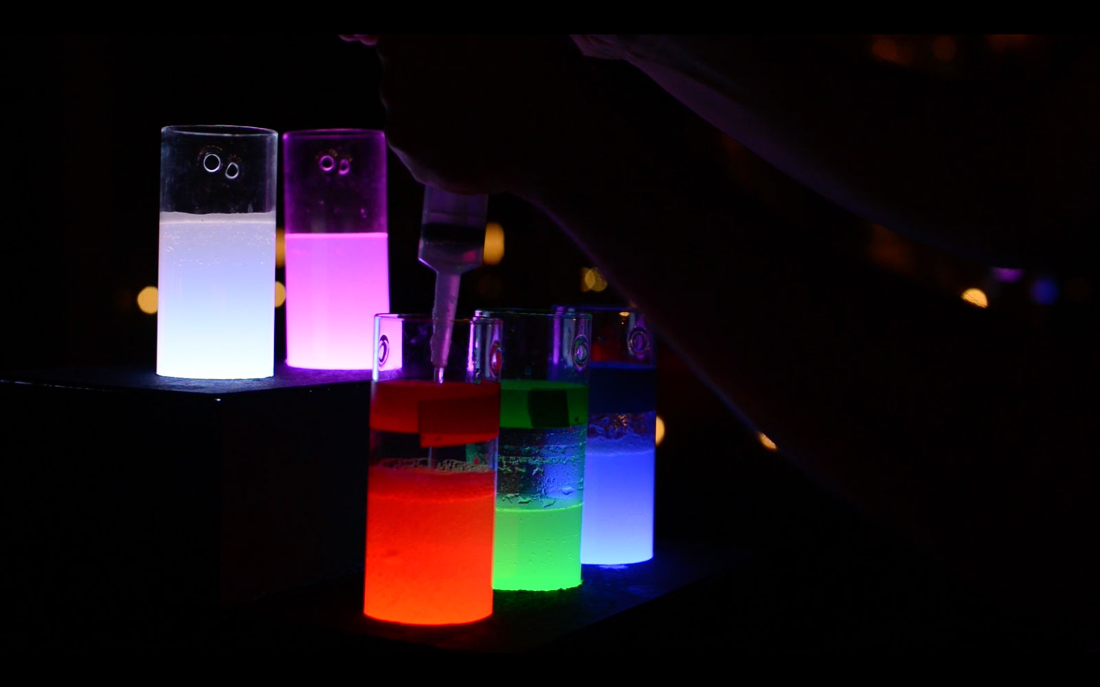
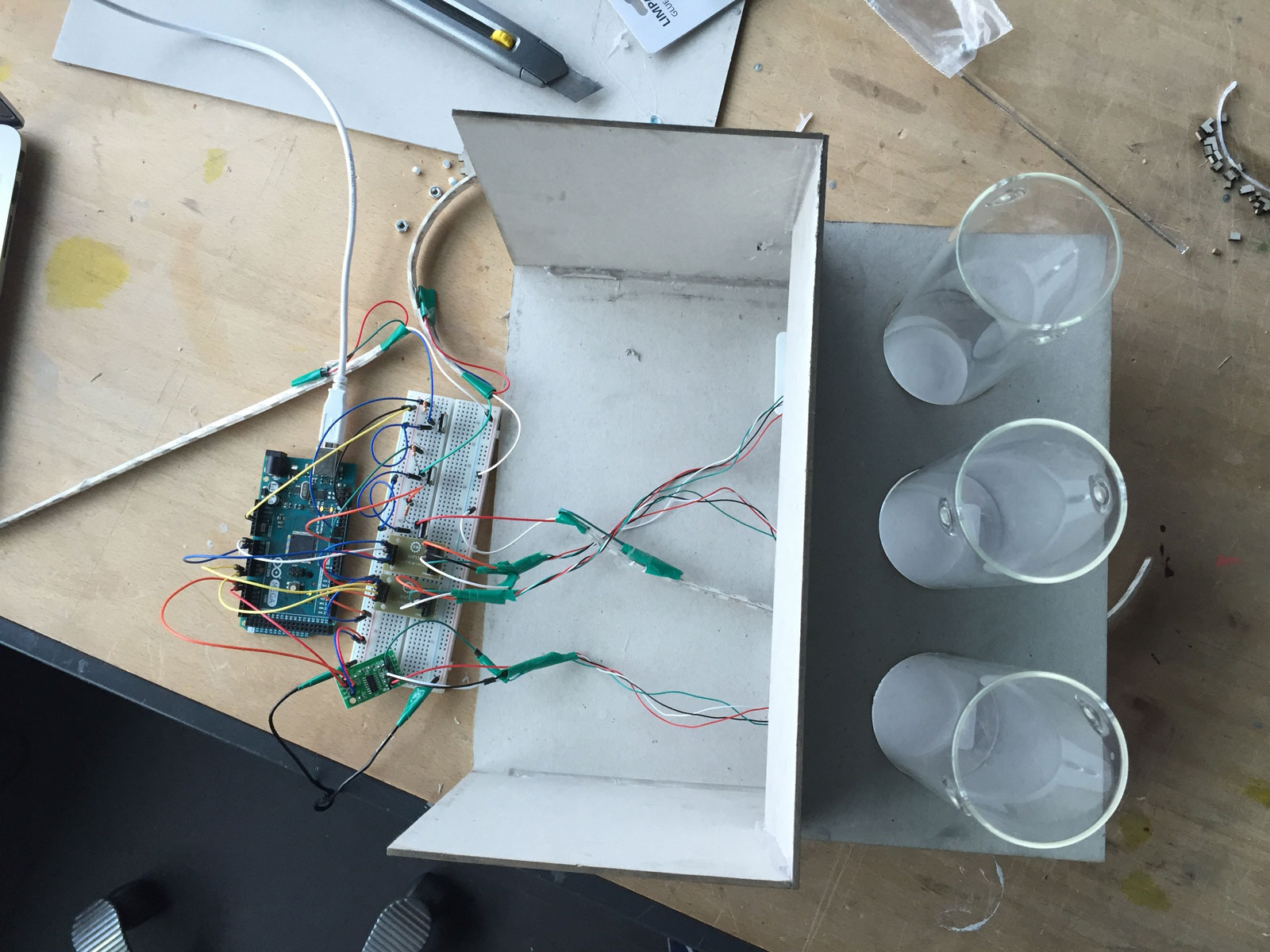
As seen here, mixing colors in real life is simple enough to understand, if difficult to perfect. With red, green and blue, any color in the rainbow can be produced, and the same can be done virtually using these digital RGB components. To help make color theory easier to grasp, Justin Daneman and Tore Knudsen developed a tangible interface that employs an Arduino to detect the fill levels of three cylinders, which represent red, green, and blue.

The intensity of each color is increased by pouring more water into the corresponding container, and decreased by removing it with a syringe. In one mode, users can explore how RGB colors create and affect a digital image on a computer screen, which in this case is Leonid Afremov’s painting “Misty Mood.” A second Color Challenge mode places a random color onscreen—or even in another glass—and participants try to match it by correctly proportioning the three liquid containers.

Colorwise is a physical game and exploration concept that aims to create awarness about digital color theory. More spiecifically, the RGB color system. Through a tangible interface of three cylinders, you mix different combinations of red, green and blue. This is done with water which works as a metaphor for digital data. By rearranging the water, a feedback of aesthetic visual and audio is experienced.

You can read more about Colorwise on its page here, and see a demo of it below!

Another Arduino Compatible? This Time, It’s A Sony

When it comes to microcontroller development boards, we have a plethora of choices at our disposal. Each has its strengths and weaknesses, be they associated with its support and community, its interface capabilities, or its choice of processor family. Most boards you’ll find in our communities come from niche manufacturers, or at least from manufacturers who started as such. Just occasionally though along comes one whose manufacturer you will have heard of, ever whose manufacturer the Man in the Street will have heard of.

Which brings us neatly to today’s story, the quiet announcement from Sony, of a new microcontroller development board called the Spritzer. This is Arduino compatible in both physical footprint and IDE, is intended for IoT applications, and packs GPS, an audio codec, and an ARM Cortex M4 at 156 MHz. There is a Japanese page with a little more detail (Google Translate link), on which they talk about applications including audio beam forming with up to eight microphones, and a camera interface. 

The board is due to be available sometime early next year, and while it looks as though it will be an interesting device we’d sound a note of caution to Sony. It is not good enough to have an amazing piece of hardware; the software and community support must be more than just make-believe. If they can crack that then they might just have a winner on their hands, if they fail to make any effort then they will inevitably follow Intel into the graveyard of also-ran boards.

Thanks [Chris] for the tip.


Filed under: hardware
Hack a Day 13 Aug 15:00

Visual Development with XOD

Early programmers had to represent code using binary, octal, or hex numbers. This gave way quickly to representing programs as text to be assembled, compiled, or interpreted by the computer. Even today, this remains the most common way to program, but there have been attempts to develop more visual ways to create programs graphically. If you program microcontrollers like the Arduino, you should check out XOD and see how you like visually creating software. The software is open source and currently, can target the Arduino or Raspberry Pi.

You can launch the IDE in a web browser or download a local copy. You transfer nodes from a palette into a grid-like workspace. These nodes might be inputs, outputs, processing blocks, or represent real-world I/O devices. Nodes have inputs and outputs of specific types and you connect them together, connecting like types only, although there are blocks that can convert.

For example, to the right is a simple set of nodes that forms the prototypical flashing LED program. A clock node creates a pulse that toggles a memory element and a digital output accepts both the signal and a constant value indicating which port it represents.

This is a simple example, but it does show the intuitive flow of joining nodes. There is a reasonable array of node types and sufficient documentation.

There are out-of-the-box nodes for ultrasonic sensors, temperature sensors, servos, LCDs, buttons, and H-bridges. You can create your own super-nodes (patches) and you also can make multiple disjointed flows to execute more than one task at a time.

When you generate the code you get a lot of boilerplate that sets up the run time system and the nodes you use. Your main code appears to be in an evaluate function. For example, here’s a snippet of the code that corresponds to the simple graphical blink program:

void evaluate(Context ctx) {
State* state = getState(ctx);
TimeMs tNow = transactionTime();
TimeMs dt = getValue<input_IVAL>(ctx) * 1000;
TimeMs tNext = tNow + dt;

if (isInputDirty<input_RST>(ctx)) {
if (dt == 0) {
state->nextTrig = 0;
clearTimeout(ctx);
} else if (state->nextTrig < tNow || state->nextTrig > tNext) {
state->nextTrig = tNext;
setTimeout(ctx, dt);
}
} else {
// It was a scheduled tick
emitValue<output_TICK>(ctx, 1);
state->nextTrig = tNext;
setTimeout(ctx, dt);
}
}

There are a few rough edges, which isn’t surprising for new software. For one thing, nodes have fixed numbers of inputs and outputs. So if you want, for example, a ten-input AND gate, you’ll have to build it. Another apparent issue is there is no way we found to select a lot of items at once. If you decide you want to move a whole bunch of nodes down to make room for something new, you are going to be in for a lot of work.

There are other drag-and-drop programming languages, of course. We’ve covered Scratch for the Arduino and the Raspberry Pi, before. However, this is a dead simple way to try flow-based programming with minimal setup.


Filed under: Arduino Hacks, Raspberry Pi

An Arduino-powered backlit Clemson Tiger Paw

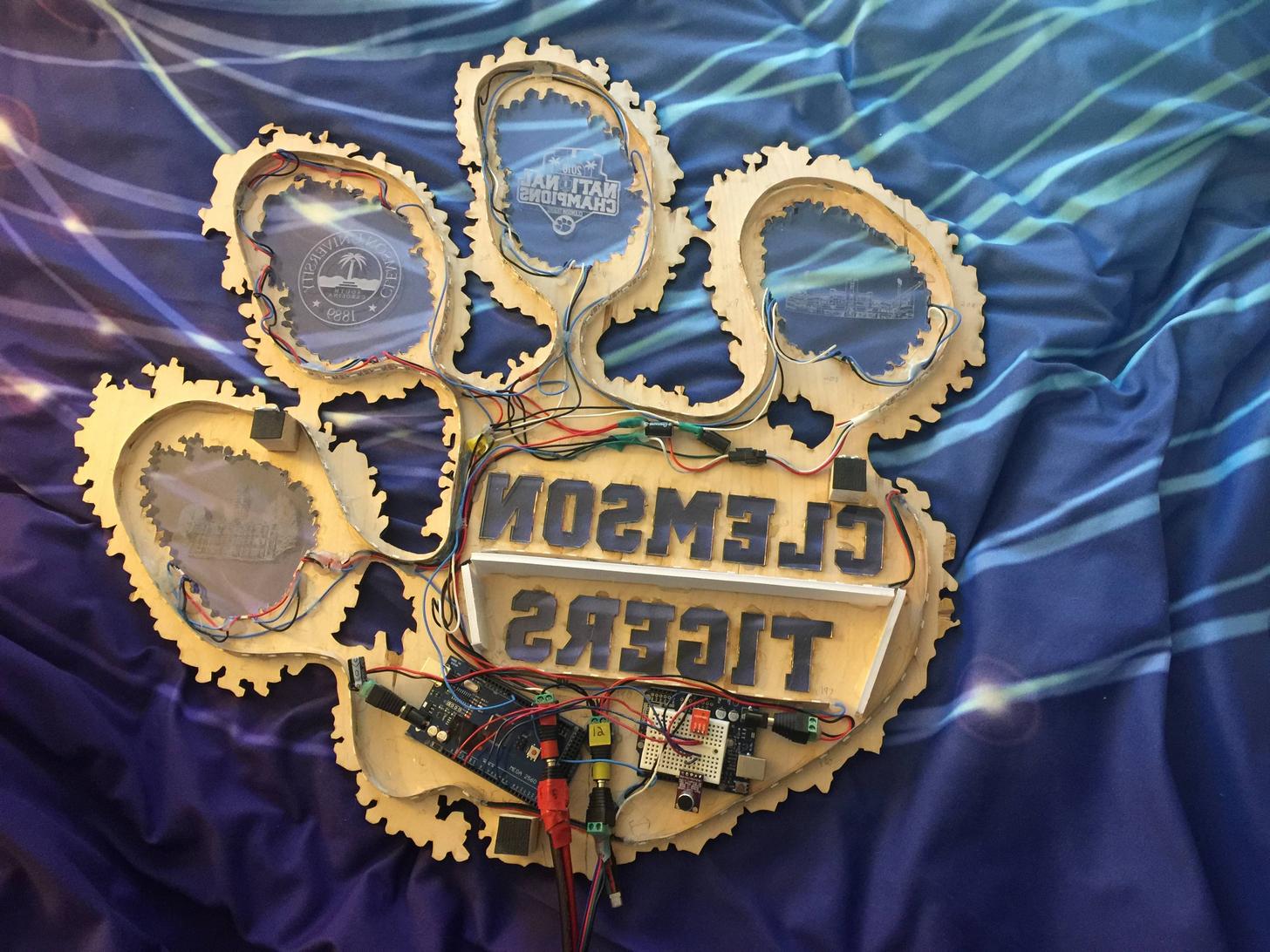
Most people support their school or favorite sports team by buying a shirt or tuning into games. Jacob Thompson, however, took things one step further and created his own Arduino-powered, backlit Clemson Tiger Paw.

Thompson’s “WallPaw,” as he calls it, uses an Arduino Uno to receive signals from an infrared remote and to pick up sounds with a small microphone. This information is passed on to an Arduino Mega, which controls a five-meter-long strip of WS2812 LEDs to provide lighting effects.

He notes that it would be possible to use only one Arduino board for everything, but patterned his code after this tutorial that included two. The paw itself is cut out of wood and clear acrylic, allowing the lights underneath to shine through nicely.

You can see the build in action below and find more details on Thompson’s website here.

Build an arcade-style hoops game with Arduino and LEGO

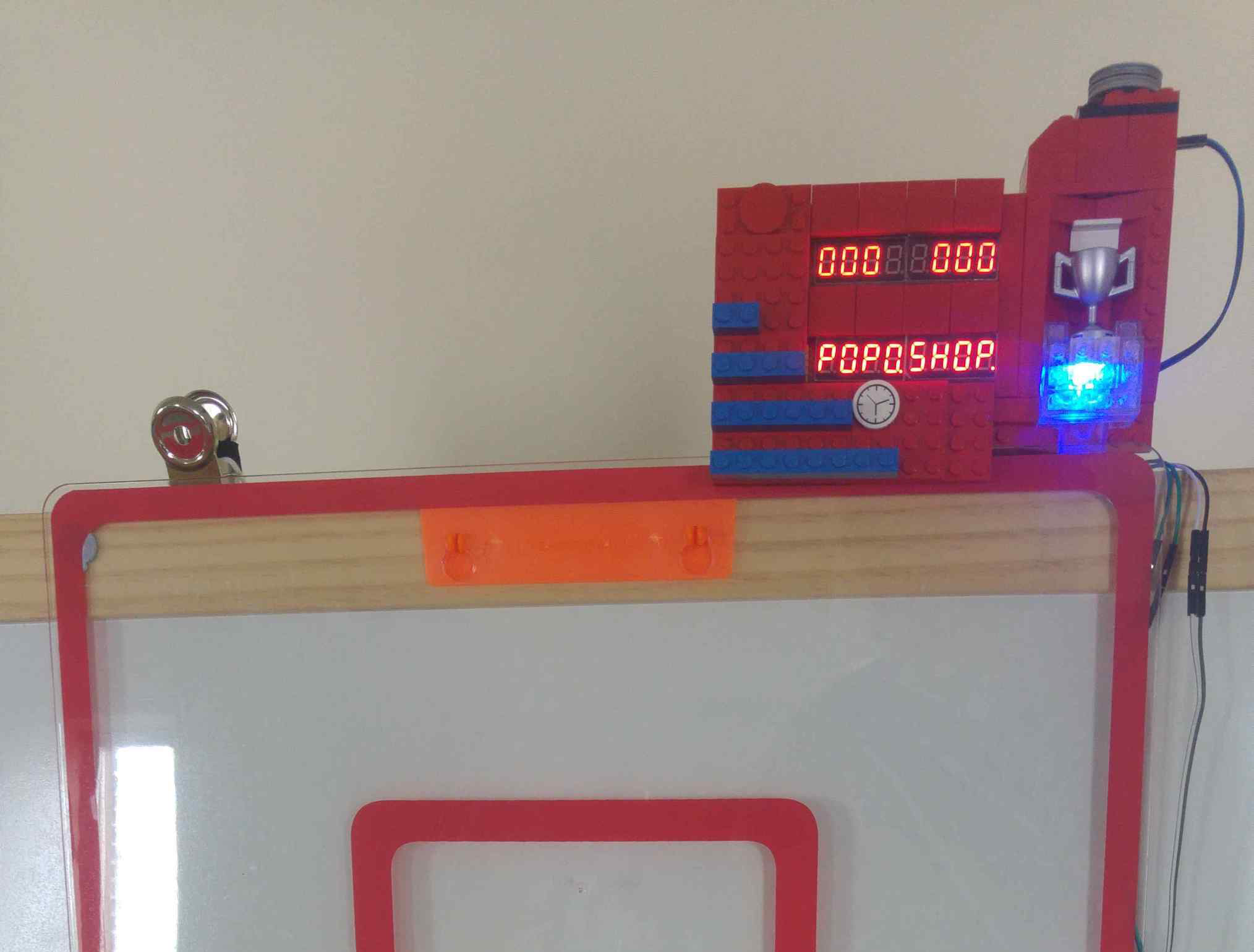
You may be familiar with “Pop-A-Shot” at arcades and amusement parks, which allows you to shoot baskets at a hoop for fun and prizes. This Maker, apparently unsatisfied with not having one of these at home, decided to duplicate the game with the “Pop o Shop.”

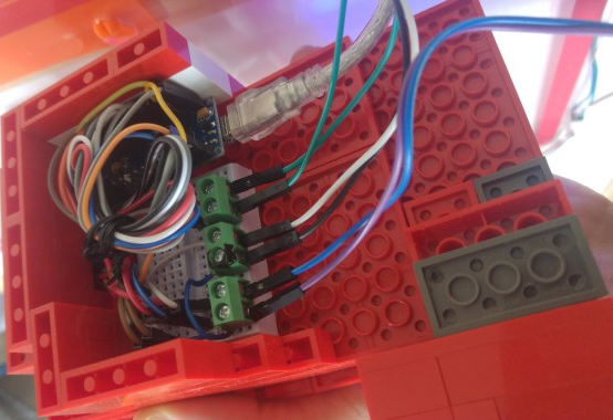
In this version, an ultrasonic sensor in the hoop tells an Arduino Nano when a shot has been registered, while two 7-segment displays inside of a LEGO scoreboard show the current count, time remaining, and high score. There is also an RGB LED that turns green after every made basket and changes color with a new top score.

Incidentally, one of the displays can also spell out “POPOSHOP,” which dictated the name of the game, since there is no “T” character in the LedControl library used! For more info and code, be sure to check out the “Internet of LEGO” build log!

CircuitPython Snakes its Way onto Adafruit Hardware

We sit down to talk with Scott Shawcroft, an engineer at Adafruit, to discuss their hardware transition to CircuitPython.

Read more on MAKE

The post CircuitPython Snakes its Way onto Adafruit Hardware appeared first on Make: DIY Projects and Ideas for Makers.

CircuitPython Snakes its Way onto Adafruit Hardware

We sit down to talk with Scott Shawcroft, an engineer at Adafruit, to discuss their hardware transition to CircuitPython.

Read more on MAKE

The post CircuitPython Snakes its Way onto Adafruit Hardware appeared first on Make: DIY Projects and Ideas for Makers.

An Arduino fidget spinner arcade controller

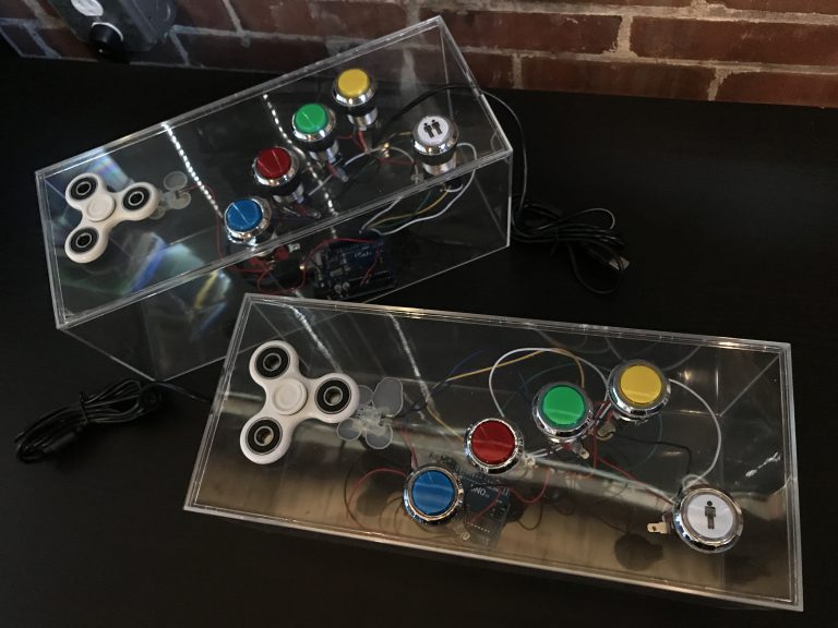
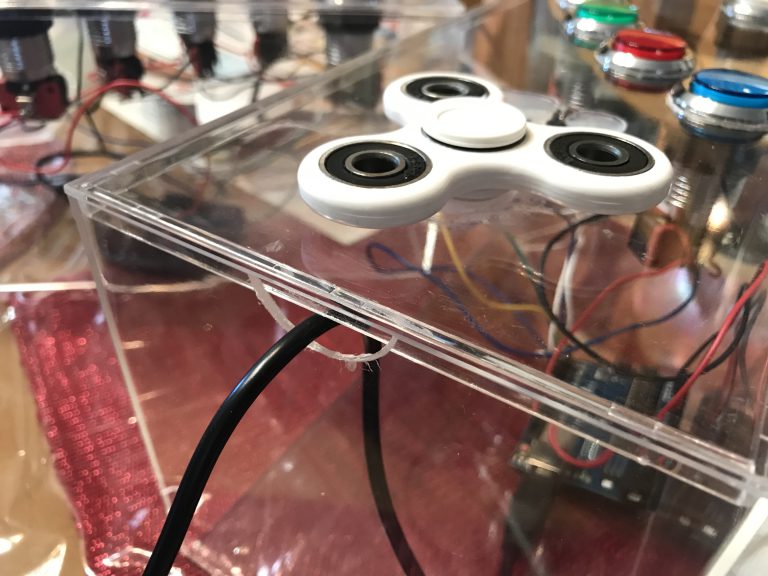
Apparently unsatisfied with existing video game input devices, game designer Rob Santos created his own using, what else, fidget spinners. His system combines a spinner and five buttons on a pair of controllers to interface with Flock Off, an arcade game loosely based on Flappy Bird.

To register spinner input, a magnet is embedded on each lobe, triggering a Hall effect sensor three times per revolution when spun. An Arduino in each control box reads these signals, then sends this information, along with button inputs, to the game via USB accessible through a serial port.

Although using the Uno means that the game must be programmed especially for this type of input, Santos notes that using an HID-capable board, such as the Leonardo, would give it the capability to act as keyboard input by itself.

Create an interactive laser sheet generator with Arduino

What’s better than a laser? How about two rapidly rotating lasers, attached to servo motors and controlled by an Arduino Mega? That’s exactly what Jon Bumstead made with his “Interactive Laser Sheet Generator.”

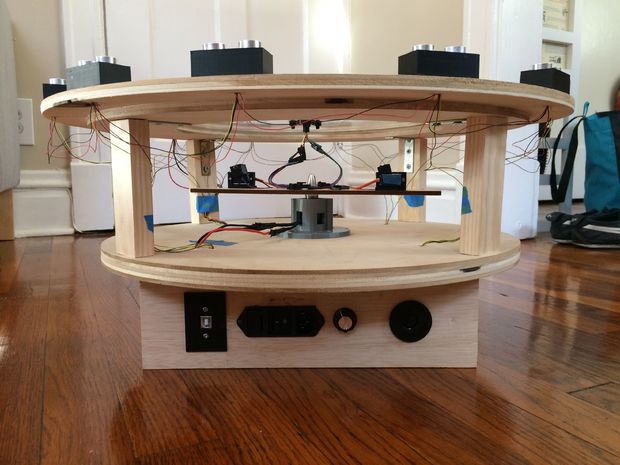
In addition to controlling the lasers, his device can sense hand motion on top of it using an array of 12 ultrasonic sensors, and can even coordinate music through a built-in MIDI output.

As seen in the demonstration video, Bumstead’s project–which was constructed with the help of a CNC router–looks like a cross between a coffee table and a test fixture for a space vehicle. When activated, a brushless motor spins the two lasers at a high speed, while the Mega controls the laser angles via two servos, creating a unique vortex-like light show!

I included distance sensors in the device so that the laser sheets could be manipulated by moving your hand towards them. As the person interacts with the sensors, the device also plays music through a MIDI output. It incorporates ideas from laser harps, laser vortexes, and POV displays. The instrument is controlled with an Arduino Mega that takes in the inputs of ultrasonic sensors and outputs the type of laser sheet formed and music generated. Due to the many degrees of freedom of the spinning lasers, there are tons of different laser sheet patterns that can be created.

You can find more details on the laser sheet generator on Instructables.