On April 18th, a team from Arduino Education made it to the museum Ciudad de las Artes y las Ciencias in Valencia to participate in the CTC Valencia Fair. A total of 1,200 students (out of 1,500 people in attendance) participated in the five-hour-long event where the students exhibited what they had been producing over the last couple of months.
CTC, the Creative Technologies in the Classroom initiative
CTC started as a project in the region of Castilla La Mancha in Spain. I was asked what kind of process could be implemented in order to bring teachers and school up to speed with new educational technologies. Back then, in 2012, I had been teaching students from many different disciplines, mostly at the university level: interaction design, medicine, engineering, product design, mathematics, multimedia, fine arts… I had also been working with upper secondary school teachers from Spain, Argentina, and Sweden in the creation of small curriculums introducing interactive technologies a part of more transversal teaching in subjects like science and design.
When asked by the people in charge at the regional centre for educators in Castilla La Mancha, I suggested a quick iterative design process that began with a collective survey to teachers in 25 schools and followed by a curriculum suggestion on topics that they considered relevant. The most complex aspect in this process was how to design interventions in the way of implementing this programme so that I could incorporate the teachers’ as well as the students’ opinions and debug the content as we went. CTC has over 25 different mid-size experiments designed to help a class get acquainted to work in a project-based learning methodology through an iterative process.
The first CTC fair brought together over 400 students from all over Castilla La Mancha that presented 100-plus projects. Almost five years later, we have witnessed yet another incredible fair with very nice results, only this time in Valencia.
What has changed
CTC now includes experiments with wireless technology, accelerometers, capacitive sensing, motors, lights, and other interesting tricks, thanks to using the Arduino 101 board that comes with BLE, an IMU, and some other goodies. Students are introduced to programming using Processing and the Arduino IDE. But not everything is coding, given our pedagogic approach, they learn how to work in groups, search for technical information, organize time, and present their results…
On the Arduino side, we have jumped from having a good old WordPress site to enable communication between the students, to a full-fledged platform that is being augmented with new materials and courses on a yearly basis. The content works for both the classic IDE and the more modern Create IDE. At the same time, we have implemented a hotline where teachers can ask questions directly to Arduino’s support specialists. Of course, there is a forum just for teachers to talk to one another and the Arduino forum still supporting them; but we have learned that teachers like one-to-one communication because each school is somehow different in terms of equipment, network facilities, classrooms and policies, and social environment–teachers, students, and their families.
We have learned about complex deployments; for example, in Valencia there is a special Linux distribution called Lliurex that we had to hack in order to get the IDE running properly. During a previous project in Andalucia, teachers had no administration password to the computers! Well, we did figure things out and got the project to work. So big kudos to our support team that had to get out the hacker hoodie and code a clever solution!
Also, for the CTC webinars we make on a bi-weekly basis, we have changed our online seminar backend to have a much more efficient one. Now our calls allow full interaction with the participants that can be invited to talk and share screens when needed instead of simply having a chat line back.
Valencia is cool, isn’t it?
We had a CTC fair at the Ciudad de las Artes y las Ciencias, a museum by Santiago Calatrava in the shape of a huge boat put upside-down. There are fountains surrounding the building, the weather was amazing (remember I am coming from Sweden, where we just had the worst winter in 10 years, so anything over 15°C is good at this point), the organizers from CEFIRE (the teacher organization in Valencia’s region) made a great preparation of the location, schools arrived on time, the show went fine-great-FABULOUS… so yes, Valencia is cool, and the so was the CTC fair.
On stage we could see almost 30 projects being presented by the students, while we conducted a two and a half-hour livecast for those interested in seeing the projects from anywhere in the world. We held 15 interviews, but unfortunately we couldn’t show everything happening, considering that there were a more than 150 projects on display!
The following video is a summary of livestream from the museum; for your benefit, we have chosen some highlights of the broadcast I conducted throughout the day.
The interviews were conducted in Spanish, which is another reason for the summary; but if you are interested in the actual interviews, check out the following video.
Some seriously nice projects
I cannot stop being surprised by the amount of creativity students show when making projects. Even if I attend an average of five events of this nature per year, I keep on finding projects that make an impression in me. Students are always challenging any pre-conceptions I might have about what could be done with something as simple as an Arduino board. The one thing teachers keep on saying again and again is that it was them, the students, that pushed the process forward, that once they got started with the course, it was hard not to get carried away by the students initiative. The role of the teachers is playing the realist, trying to make sure the projects come to an end. That said, here some of the things I saw while walking around in the faire.
Probably the most impressive project I came across was a model of the Hogwart’s castle inspired by the Harry Potter movies. It took the students four months to build the entire project. It was a replica of the castle, so heavy that it needed four people to carry it around. It had dragons flying around one tower, the lights could be turned on and off… there was even a fountain with running water! The whole mode could be controlled via Bluetooth from an Android tablet. In total, the model took three months to construct, the students said, while making the electronics and software work took one month.

On the other side of the spectrum, I could play with a small arm wrestling toy made by a single student that took only 5 hours to build. You can check out the interview with the student in the above-posted videos. While the project seems to be simple, it is clear that the student had become quite knowledgeable in the craft of making projects, since he had figured everything for the project on his own without any external help.
One last project I would like to talk about was a small drawing machine comprised of mechanics from DVD drives that could replicate small drawings (less than 10x10cm big) using a pen. The students explained that it barely worked the night before, but that they finally figured out the calibration process minutes before leaving for the faire. The results, as you can see on the video interviews, are quite amazing. They can export drawings using the open source program Inkscape in a format (G-code) their machine can understand, this allows them to trace any kind of vectorized drawing and reproduce it with their machine.
There were a lot more projects, take a look at the videos and pictures in this blog post. We will be presenting some others as part of the Arduino Livecast series in the the future. If you want to know more, just subscribe to Arduino’s YouTube channel and you will get weekly notifications on our videos.
Acknowledgements
The CTC Valencia project has been possible thanks to the generous contribution of EduCaixa, the on-site collaboration of the technical body at CEFIRE, the kind support of the regional government of Valencia – the Generalitat -, and the help of our old friend Ultralab.
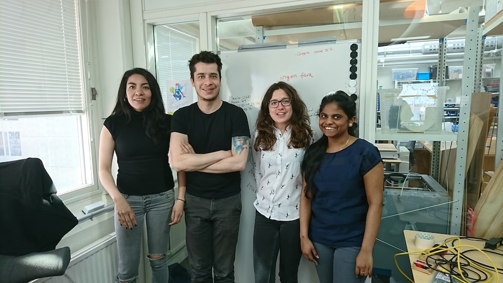
From everyone involved in the project, big thanks to Ismael and Oscar, who believed in the project and pushed for it. Personally I want to thank Nerea who coordinated the project, and Roxana who was there making it happen from Arduino on a weekly basis; also Carla and Carlos who covered up when needed. Finally to Laura, who worked long evenings on top of everything else to make all of graphics needed for the fair.
At a more technical level, we have a new revision to the look and feel of the CTC project site coming, and it is looking awesome. Marcus, Gabrielle, Luca and everyone working with the UX in Arduino are creating one of the best-looking educational experiences ever. If not only the content is good, but if it feels good and looks good, then the experience will be excellent!
Do you want CTC in your world?
If you want to be part of the CTC initiative, visit Arduino Education’s website, subscribe to the Arduino Education Newsletter [at the bottom of that site], or send us a request for more information via email: ctc.101@arduino.cc.
[Photos by Pablo Ortuño]


 LED cubes, while fascinating, aren't particularly new. We've seen quite a few of them. However, this one, made by Instructibles user mosivers, adds a new twist.