Posts with «arduino» label

Vintage ham radio transformed into epic party game prop

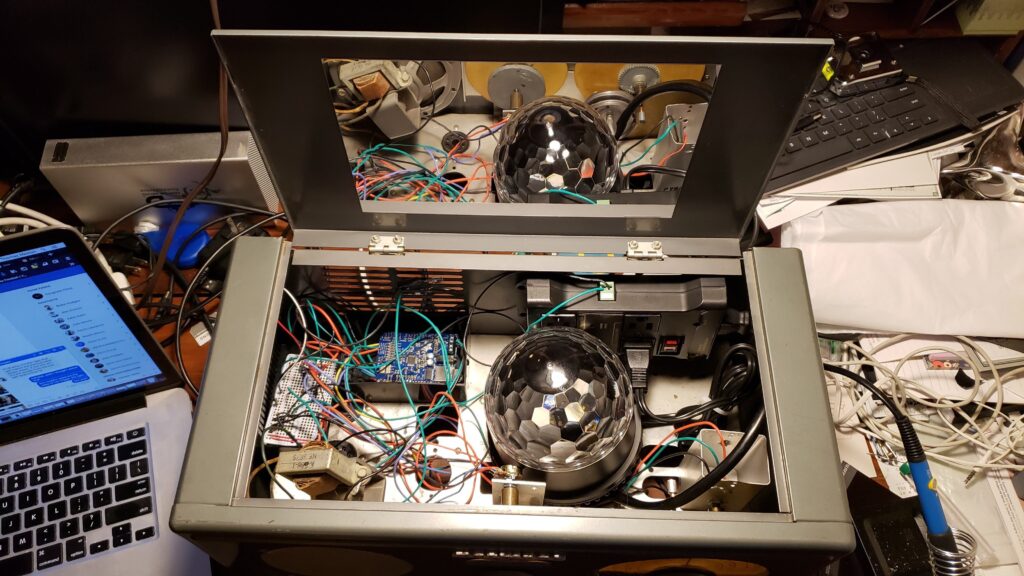
Maker Thomas Meston needed a “mysterious looking device” that allows players to enter codes obtained via an original party game. What he came up with is entitled “Dr. Hallard’s Dream Transmission Box,” and consists of an Arduino, a party light, a smoke machine, and other components stuffed into a broken National NC-33 ham radio.

This radio makes a really excellent enclosure for the electronics inside, and when the device is properly activated the winning team hears a special message via an Arduino Uno-controlled MP3 shield, accompanied by laser lights and smoke. 

How it works:

  • When the box is switched on you hear static and see a yellow light. The device is ready for the codes to be entered.
  • Once all three dials have been set, the player switches the bottom toggle to “send” state, the box will message back whether team blue or team red has entered any codes with a quick flash of either a red or blue led.
  • If all three dials are set to red codes, the red team wins and hears a special message through the speaker just for them. The laser lights and smoke machine will be activated at the same time.
  • If all three dials are set to blue, a different message will play as well as activating the smoke machine and laser lights.

More info on the project can be found here, and while it might seem like a shame to modify this kind of vintage equipment, Meston notes that he sees this as giving it a nice second life since it was previously non-functional.

Arduino Blog 02 Oct 13:30

A Better Battery Arduino

We’ve seen [Johan]’s AA-battery-sized Arduino/battery crossover before, but soon (we hope!) there will be a new version with more MIPS in the same unique form factor! The original Aarduino adhered to classic Arduino part choices and was designed to run as the third “cell” in a 3 cell battery holder to relay temperature readings via a HopeRF RFM69CW. But as [Johan] noticed, it turns out that ARM development tools are cheap now. In some cases very cheap and very open source. So why not update an outstanding design to something with a little more horsepower?

The Aarduino Zero uses the same big PTH battery terminals and follows the same pattern as the original design; the user sticks it in a battery holder for power and it uses an RFM69CW for wireless communication. But now the core is an STM32L052, a neat low power Cortex-M0+ with a little EEPROM onboard. [Johan] has also added a medium size serial flash to facilitate offline data logging or OTA firmware update. Plus there’s a slick new test fixture to go along with it all.

So how do you get one? Well… that’s the rub. It looks like when this was originally posted at the end of 2017 [Johan] was planning to launch a Crowd Supply campaign that hasn’t quite materialized yet. Until that launches the software sources for the Zero are available, and there are always the sources from the original Aarduino to check out.

How to Build an Inverter, and Why Not to Bother

It’s ridiculously easy to lay hands on a cheap DC-to-AC inverter these days. They’re in just about every discount or variety store and let you magically plug in mains powered devices where no outlets exist. Need 120- or 240-VAC in your car? No problem – a little unit that plugs into the lighter socket is available for a few bucks.

So are these commodity items worth building yourself? Probably not as [GreatScott!] explains, but learning how they work and what their limitations are will probably help your designs. The cheapest and most common inverters have modified square wave outputs, which yield a waveform that’s good enough for most electronics and avoids the extra expense of producing a pure sinusoidal output. He explains that the waveform is just a square wave with a slight delay at the zero-crossing points to achieve the stepped pattern, and shows a simple H-bridge circuit to produce it. He chose to drive the output section with an Arduino, to easily produce the zero-crossing delay. He uses this low-voltage inverter to demonstrate how much more complicated the design needs to get to overcome the spikes caused by inductive loads and the lack of feedback from the output.

Bottom line: it’s nice to know how inverters work, but some things are better bought than built. That won’t stop people from building them, of course, and knowing what you’re doing in this field has been worth big bucks in the past.

Watch the Snappy, Insect-like Moves of this DIY Quadruped Robot

Some legged robots end up moving with ponderous deliberation, or wavering in unstable-looking jerks. A few unfortunates manage to do both at once. [MusaW]’s 3D Printed Quadruped Robot, on the other hand, moves in rapid motions that manage to look sharp and insect-like instead of unstable. Based on an earlier design he made for a 3D printable quadruped frame, [MusaW] has now released this step-by-step guide for building your own version. All that’s needed is the STL files and roughly $50 in parts from the usual Chinese resellers to have the makings of a great weekend project.

The robot uses twelve SG90 servos and an Arduino nano with a servo driver board to control them all, but there’s one additional feature: Wi-Fi control is provided thanks to a Wemos D1 Mini (which uses an ESP-8266EX) acting as a wireless access point to serve up a simple web interface through which the robot can be controlled with any web browser.

Embedded below is a brief video. The first half is assembly, and the second half demonstrates the robot’s fast, sharp movements.

We love it when robots show some personality, like this adorable little quadruped robot that can make small jumps.

Thanks to [Baldpower] for the tip!

Custom “doorbell” flashes house lights for the hearing impaired

Darren Lewis’ parents both have a difficult time hearing the doorbell. He experimented with an off-the-shelf flashing light, but found that could only really be seen when they were in the room—an obvious problem. In response to this, Lewis decided to make his own system that flashes multiple house lights at the same time.

His device uses an Arduino Nano to detect the stock doorbell speaker voltage. When a press is sensed, it then activates a RF light switch via a modified remote, using an output pin and opto-isolator to substitute in for the normal button press. 

It’s a clever hack, and certainly one that will certainly help alleviate doorbell frustration in the future!

Maker Faire NY: Developing for the Final Frontier

The cost of getting a piece of hardware into space is now cheaper than ever, thanks in no small part to the rapid progress that’s been made by commercial launch providers such as SpaceX. In the near future, as more low-cost providers come online, it should get even cheaper. Within a few years, we could be seeing per kilogram costs to low Earth orbit that are 1/10th what they were on the Space Shuttle. To be sure, this is a very exciting time to be in the business of designing and building spacecraft.

But no matter how cheap launches to orbit get, it’ll never be cheaper than simply emailing some source code up to the International Space Station (ISS). With that in mind, there are several programs which offer students the closest thing to booking passage on a Falcon 9: the chance to develop software that can be run aboard the Station. At the 2018 World Maker Faire in New York we got a chance to get up close and personal with functional replicas of the hardware that’s already on orbit, known in space parlance as “ground units”.

On display was a replica of one of the SPHERES free-flying satellites that have been on the ISS since 2006. They are roughly the size of a soccer ball and utilize CO2 thrusters and ultrasonic sensors to move around inside of the Station. Designed by MIT as a way to study spaceflight techniques such as docking and navigation without the expense and risk of using a full scale vehicle, the SPHERES satellites are perhaps the only operational spacecraft to have never been exposed to space itself.
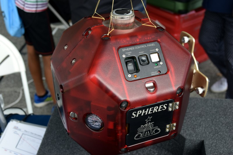
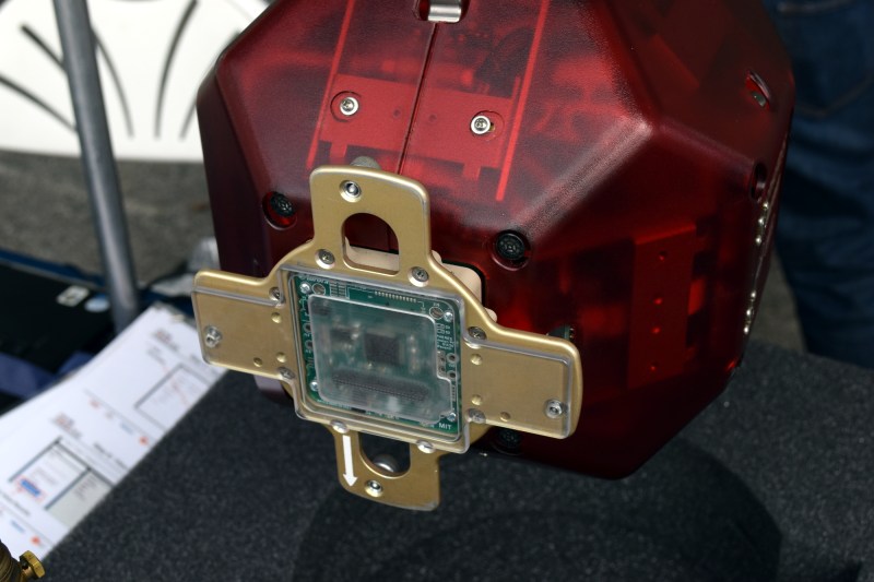
MIT now runs the annual “Zero Robotics” competition, which tasks middle and high school students with solving a specific challenge using the SPHERES satellites. Competitors run their programs on simulators until the finals, which are conducted using the real hardware on the ISS and live-streamed to schools.

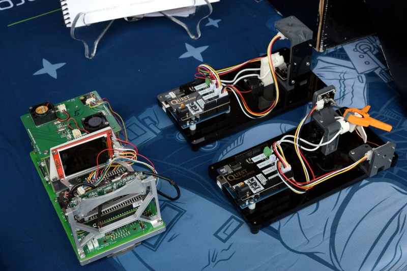
We also saw hardware from “Quest for Space”, which is a company offering curricula for elementary through high school students which include not only the ground units, but training and technical support when and if the school decides to send the code to the matching hardware on the Station. For an additional fee, they will even work with the school to design, launch, and recover a custom hardware experiment.

Their standard hardware is based on off-the-shelf platforms such as Arduino and LEGO Mindstorms EV3, which makes for an easy transition for school’s existing STEM programs. The current hardware in orbit is setup for experiments dealing with heat absorption, humidity, and convection, but “Quest for Space” notes they change out the hardware every two years to provide different experiment opportunities.

Projects such as these, along with previous efforts such as the ArduSat, offer a unique way for the masses to connect with space in ways which would have been unthinkable before the turn of the 21st century. It’s still up for debate if anyone reading Hackaday in 2018 will personally get a chance to slip Earth’s surly bonds, but at least you can rest easy knowing your software bugs can hitch a ride off the planet.

View the sea floor in 360° with this Arduino-powered dropcam

A dive mask or even SCUBA tanks are a great way to explore the ocean, but at depths of much more than 30 meters, things become a bit dicey. 1,000 meters is generally unthinkable for amateur divers but WorkshopScience has come up with a way to explore these regions without undue danger.

His device, developed during an internship with Blue Robotics, is touted as the world’s first consumer deep-sea dropcam. It’s able to dive to 1,000 meters and capture 360° video, as well as pressure and temperature readings. 

When a sufficient amount of time has passed, an Arduino board releases a weight by disintegrating a length of nichrome wire with electrical current. It then floats to the surface for data analysis. How it works, along with a resulting 360° video can be seen below.

Giant Connect Four Pits You Against the Computer

You can build a Connect Four solver in software, but it won’t be all that much fun. Now apply that same automation to a 15-foot-tall plywood version of the classic board game and you’ve just created a smile-making-machine for everyone within eyesight. Behold the Mono-Purpose Automated Robot Versed In Connnect4 (Marvin) which Ben and Jonathan dreamed up on their way home from Maker Faire last year, and made into their exhibit this year.

On the physical side of things they got really creative in lifting the discs and sorting them into the column chosen by the software brain of the game. A chain travels along one side with fingers every few feet. The fingers travel along the channel, lifting the discs. Those fingers are a couple of bolts, with some metal filler, all epoxied into one solid unit.

At the top of the disc elevator, and at the top position of each column in the gaming board, there are IR reflectance sensors which send feedback to the Arduino that drives the hardware. This proved a major issue during setup the day before the Faire. The reflectance sensors are just blasting out IR and not using a carrier signal. In direct sunlight, the detector was in a constant state of being tripped. After some trial and error, the logic for the sensors was flipped to detect the absence of sunlight by placing black plastic behind that top row of the board and putting duct tape over the IR emittors.

There’s a router and laptop rolled into the system. The Arduino makes an HTTP request to software on the laptop. In addition to determining where the next move should be made, the laptop is connected to a large screen which shows the current state of the gaming board. This is a head-to-head, human versus machine game. The human player drops their discs from the top of the board using a paint roller that hooks into a hole at the center of the disc. This way the player’s disc passes by the sensors, triggering the machine’s next move.

It’s a clever build and due to the sheer size it’s pretty awesome they were able to get it to the Faire from Philadelphia. Don’t miss the video after the break that shows off the fun and excitement of this gaming giant.

Three-axis rotary machining with Arduino

For many years CNC machining was the purview of well-equipped shops and manufacturing facilities. With the availability of inexpensive control hardware, such as Arduino-based GRBL packages, this type of control has come to the (technically inclined) masses, enabling us to create complicated 2D and 3D shapes automatically.

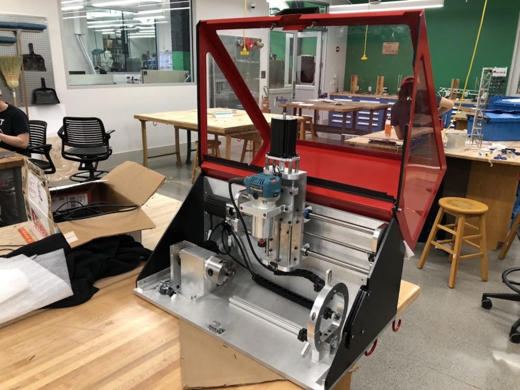
Normally, this means X, Y, and Z axes that control a cutting head, and if you wanted to much further in complexity and cost, you could add a fourth or even a fifth axis to tilt things as needed. The RotoMill, however, seen at World Maker Faire in New York, puts a different “spin” on things, substituting a stepper-controlled spindle for the Y axis. The result is a machine with unique machining capabilities, driven by an Arduino Uno running custom GRBL firmware.

As for now, the CNC can easily mill parts out of softer materials like plastic, wood, and foam, although it is designed to cut aluminum as well.

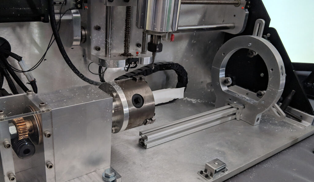
A three-axis rotary CNC built for the Mechanical Engineering senior design capstone course at Carnegie Mellon University by a team of engineering students. The CNC uses NEMA24 motors for each of the axes, with the X and Z axes actuated by lead screws, and the A (rotary) axis actuated by a worm gear. The spindle is an off-the-shelf Makita hand router, which allows for any router bit to be used.

Each motor is controlled by a stepper motor driver, which are all coordinated by an Arduino Uno running a customized version of the GRBL firmware. This is in turn controlled by a laptop running open-source GCode sending software.

To generate the GCode, we would create a 3D model of the part that we wanted to machine. We then “unwrapped” about the A axis. This basically takes the part and converts it from Cartesian coordinates to Cylindrical coordinates.

To generate the GCode, we would create a 3D model of the part that we wanted to machine. We then “unwrapped” about the A axis. This basically takes the part and converts it from Cartesian coordinates to Cylindrical coordinates.

At this point, we could take the unwrapped part and load it into Autodesk HSM, a popular industrial CAM package. This allowed us to generate a toolpath for machining the part. We basically “fooled” the CNC into thinking that it was a normal, three-axis Cartesian CNC. The trick, however, is that the Y axis is wrapped around and becomes the A axis.

Additional information and photos can be found on RotoMill’s page or Hackaday’s recent write-up.

DIY Puff-Suck Interface Aims for Faster Text Input

Puff and Suck (or Sip and Puff) systems allow people with little to no arm mobility to more easily interact with computers by using a straw-like unit as an input device. [Ana] tells us that the usual way these devices are used to input text involves a screen-based keyboard; a cursor is moved to a letter using some method (joystick, mouse emulator, buttons, or eye tracking) and that letter is selected with a sip or puff into a tube.

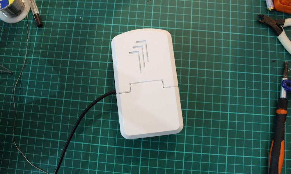
[Ana] saw such systems as effective and intuitive to use, but also limited in speed because there’s only so fast that one can select letters one at a time. That led to trying a new method; one that requires a bit more work on the user’s part, but the reward is faster text entry. The Puff-Suck Interface for Fast Text Input turns a hollow plastic disk and a rubber diaphragm into bipolar pressure switch, able to detect three states: suck, puff, and idle. The unit works by having an IR emitter and receiver pair on each side of a diaphragm (one half of which is shown in the image above). When air is blown into or sucked out of the unit, the diaphragm moves and physically blocks one or the other emitter-receiver pair. The resulting signals are interpreted by an attached Arduino.

How does this enable faster text input? By throwing out the usual “screen keyboard” interface and using Morse code, with puffs as dots and sucks as dashes. The project then acts as a kind of Morse code keyboard. It does require skill on the user’s part, but the reward is much faster text entry. The idea got selected as a finalist in the Human-Computer Interface Challenge portion of the 2018 Hackaday Prize!

Morse code may seem like a strange throwback to some, but not only does the bipolar nature of [Ana]’s puff-suck switch closely resemble that of Morse code input paddles, it’s also easy to learn. Morse code is far from dead; we have pages of projects and news showing its involvement in everything from whimsical projects to solving serious communication needs.