Posts with «arduino cnc» label

Open source microfluidics platform uses Arduino CNC control

Microfluidics deals with the manipulation of tiny amounts of liquid, and as such, specialized equipment must be used for any sort of measurable experimentation. While you could purchase an expensive commercial solution, the Poseidon system—developed by students at the California Institute of Technology—presents an excellent open source option which can be built for a fraction of the cost. 

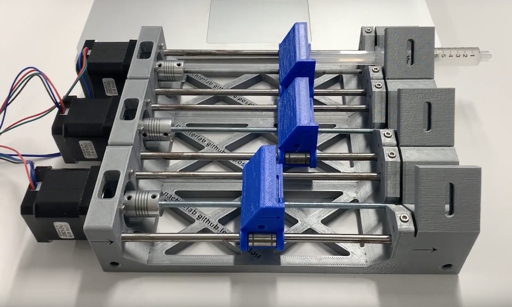
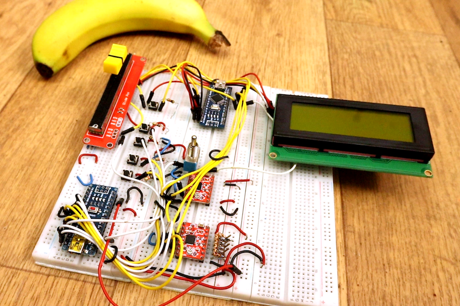
Fluid distribution is managed by a computer GUI or via a terminal window. Steppers handle each of the system’s three “axes,” and push fluid out of syringes under control of an Arduino Uno and CNC shield. A microscope is also available for a full experimental setup. 

Specific information on the project can be found on GitHub, and a number of videos on Poseidon team member Sina Booeshaghi’s YouTube page explain things further.

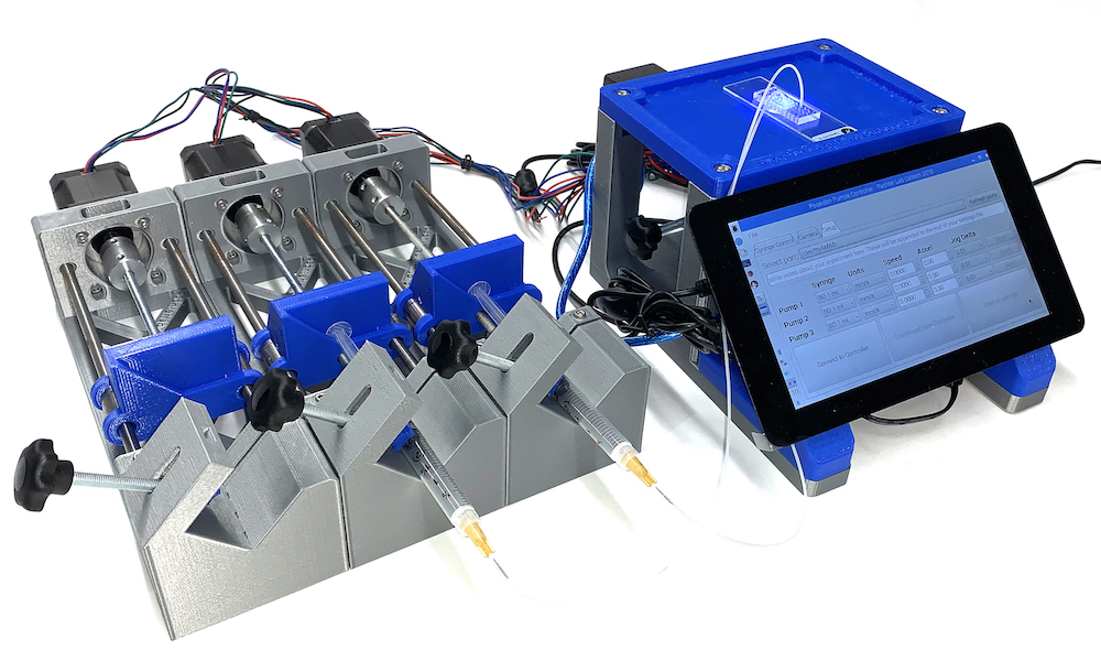
The Poseidon syringe pump and microscope system is an open source alternative to commercial systems. It costs less than $400 and can be assembled in an hour. It uses 3D-printed parts and common components that can be easily purchased either from Amazon or other retailers. The microscope and pumps can be used together in microfluidics experiments, or independently for other applications. The pumps and microscope can be run from a Windows, Mac, Linux, or Raspberry Pi computer with an easy to use GUI.

The Poseidon system was designed to be customizable. It uses the Raspberry Pi and Arduino electronics boards, which are supported by a strong ecosystem of open source hardware and software, facilitating the implementation of new functionalities.

The pump driver uses an Arduino with a CNC shield to run up to three pumps. Each pump has a stepper motor that drives lead screw which in turn moves a sled that is mounted on linear bearings. The displacement of the sled moves the syringe forward or backward allowing the user to dispel or intake liquid.

The controller station uses a Raspberry Pi with a touchscreen to connect to the Arduino and microscope via USB. Because the microscope and Arduino use USB connections, they can alternatively be connected to a computer instead of a Raspberry Pi.

Dual Arduino “CNC” control

Generally when you work with CNC machinery, you program it on a computer, then allow a controller to automatically run through a cutting routine. Arduino boards have long been used for this kind of control through the grbl software package, but YouTuber Electronoobs decided to do things a bit differently.

His setup takes input from a potentiometer and several buttons, enabling manual control of his stepper motor-driven router. An Arduino Nano powers the motors through a pair of stepper drivers, while a second Nano is then used to output distance information on an LCD screen, letting him view exactly where his cutter is at a glance.

Why use 2 Arduinos? Well, if I use only one, the code would be very difficult with too much interruptions. We have to create pulses for the motors and print on the LCD at the same time. I’ve done that and each time I was printing on the LCD, there was a small pause in the motor rotation, and if the refresh rate is fast, the motors will have a pause each time and we don’t want that. That’s why I use 2 Arduinos. One will create the pulses for the motors and the other one will count the steps and print the distance and speed.

We have 2 step motors. I’ve used NEMA 17. Each with a A4988 driver. This driver needs 3 signals from the Arduino. Enable, direction and steps. The enable pin is connected to a toggle switch so we could start to stop the motors manually. The toggle switch is also connected to the Arduinos so we could know when the motors are enabled or not. To control speed we use a lineal potentiometer and to move axis and reset position, some push buttons with pulldowns. To print the distance, I’ve used an I2S LCD screen of 20×4 but you will have the code for the 16×2 version of LCD as well.

Besides adding a nice readout to the machine, this concept could certainly form the basis for all manner of other stepper-driven devices.

Three-axis rotary machining with Arduino

For many years CNC machining was the purview of well-equipped shops and manufacturing facilities. With the availability of inexpensive control hardware, such as Arduino-based GRBL packages, this type of control has come to the (technically inclined) masses, enabling us to create complicated 2D and 3D shapes automatically.

Normally, this means X, Y, and Z axes that control a cutting head, and if you wanted to much further in complexity and cost, you could add a fourth or even a fifth axis to tilt things as needed. The RotoMill, however, seen at World Maker Faire in New York, puts a different “spin” on things, substituting a stepper-controlled spindle for the Y axis. The result is a machine with unique machining capabilities, driven by an Arduino Uno running custom GRBL firmware.

As for now, the CNC can easily mill parts out of softer materials like plastic, wood, and foam, although it is designed to cut aluminum as well.

A three-axis rotary CNC built for the Mechanical Engineering senior design capstone course at Carnegie Mellon University by a team of engineering students. The CNC uses NEMA24 motors for each of the axes, with the X and Z axes actuated by lead screws, and the A (rotary) axis actuated by a worm gear. The spindle is an off-the-shelf Makita hand router, which allows for any router bit to be used.

Each motor is controlled by a stepper motor driver, which are all coordinated by an Arduino Uno running a customized version of the GRBL firmware. This is in turn controlled by a laptop running open-source GCode sending software.

To generate the GCode, we would create a 3D model of the part that we wanted to machine. We then “unwrapped” about the A axis. This basically takes the part and converts it from Cartesian coordinates to Cylindrical coordinates.

To generate the GCode, we would create a 3D model of the part that we wanted to machine. We then “unwrapped” about the A axis. This basically takes the part and converts it from Cartesian coordinates to Cylindrical coordinates.

At this point, we could take the unwrapped part and load it into Autodesk HSM, a popular industrial CAM package. This allowed us to generate a toolpath for machining the part. We basically “fooled” the CNC into thinking that it was a normal, three-axis Cartesian CNC. The trick, however, is that the Y axis is wrapped around and becomes the A axis.

Additional information and photos can be found on RotoMill’s page or Hackaday’s recent write-up.