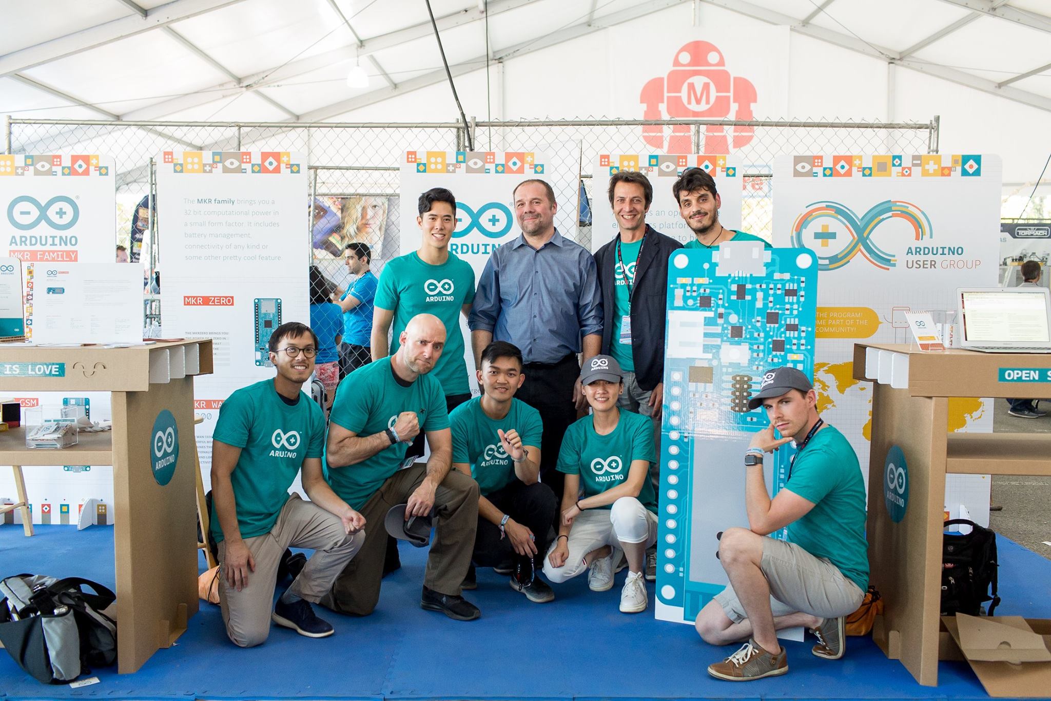
A little less than a month ago, I joined Arduino as their Chief Information Security Officer. I’ve been in touch with the team for the past couple of months and feel incredibly lucky to be part of such a talented and driven group of people.
We’re working hard on developing a robust, well-rounded security program that fits our organisation and busy improving our security posture across all departments. I am a true believer that it all starts from introducing a strong culture of security awareness — where employees feel confident and empowered to take action against security issues.
Today, I’m thrilled to announce the first release of Arduino’s Coordinated Vulnerability Disclosure (CVD) Policy.
We used some great references when putting it together and we’d like to give them a shout out here: HackerOne’s VDP guidelines, CEPS’ report on “Software Vulnerability Disclosure in Europe,” and the US DoJ Cyber Security unit’s VDP framework. We also took into consideration recent Senate testimony of experts in vulnerability disclosure in the role hackers can play in strengthening security, Dropbox’s announcement on protecting researchers and 18F’s own policy. I even wanted to publicly thank Amit Elazari Bar On, a doctoral law candidate (J.S.D.) at UC Berkeley School of Law and a Lecturer at UC Berkeley School of Information Master in Cybersecurity program for her useful advices and for providing the amazing “#legalbugbounty” standardisation project.
We’re also happy to announce that all of the text in our policy is a freely copyable template. We’ve done this because we’d like to see others take a similar approach. We’ve put some effort in to this across our teams and if you like what you see, please use it. Similarly, if you have improvements to suggest, we’d love to hear from you.
What is CVD?
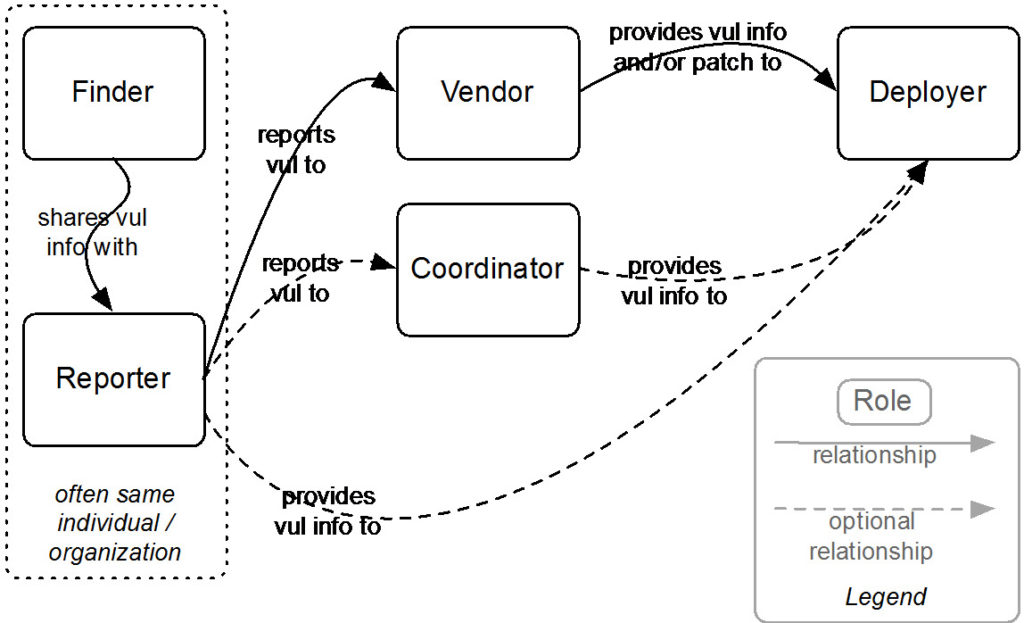
Coordinated vulnerability disclosure (CVD) is a process aimed at mitigating/eradicating the potential negative impacts of vulnerabilities. It can be defined as “the process of gathering information from vulnerability finders, coordinating the sharing of that information between relevant stakeholders, and disclosing the existence of vulnerabilities and their mitigation to various stakeholders, including the public.”
Figure 1: Relationships among actors in the CVD process. Source: “The CERT Guide to Coordinated Vulnerability Disclosure,” Software Engineering Institute, Carnegie Mellon University
Why is it important for us?
At Arduino, we consider the security of our systems and products a top priority. No technology is perfect, and Arduino believes that working with skilled security researchers across the globe is crucial in identifying weaknesses in any technology. We want security researchers to feel comfortable reporting vulnerabilities they’ve discovered, as set out in this policy, so that we can fix them and keep our information safe.
If you believe you’ve found a security issue in our products or services, we encourage you to notify us. We welcome working with you to resolve the issue promptly.
This policy describes how to send us vulnerability reports and how long we ask security researchers to wait before publicly disclosing vulnerabilities.
Where can I find it?
A copy of the policy is published on our Vulnerability Disclosure Policy page. The official document lives in GitHub. If you would like to comment or suggest a change to the policy, please open a GitHub issue.
Thank you for helping keep Arduino and our users safe!
— Gianluca Varisco