Create shapes over and over with the Dynablock 3D Printer
3D printing, while revolutionary in many aspects, generally means you’re stuck with what you print. Researchers at the University of Colorado Boulder and the University of Tokyo, however, have created a printing system called Dynablock, which attaches specialized magnetic blocks together that can used over and over.
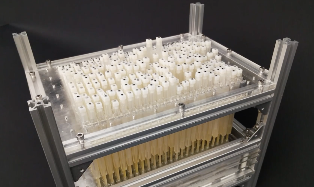
The system uses an array of 24 x 16 motors to push the blocks into position one layer at a time, giving a possible “print” resolution of 384 blocks per layer. An Arduino Uno, along with shift registers and motor drivers are used to directly control the block placement motors, and user interface is handled by a JavaScript-based application.
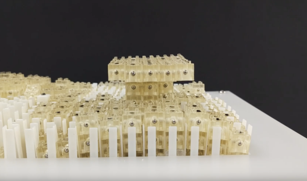
Dynamic 3D Printing combines the capabilities of 3D printers and shape displays: Like conventional 3D printing, it can generate arbitrary and graspable three-dimensional shapes, while allowing shapes to be rapidly formed and reformed as in a shape display. To demonstrate the idea, we describe the design and implementation of Dynablock, a working prototype of a dynamic 3D printer. Dynablock can form a three-dimensional shape in seconds by assembling 3,000 9 mm blocks, leveraging a 24 x 16 pin-based shape display as a parallel assembler. Dynamic 3D printing is a step toward achieving our long-term vision in which 3D printing becomes an interactive medium, rather than the means for fabrication that it is today. In this paper, we explore possibilities for this vision by illustrating application scenarios that are difficult to achieve with conventional 3D printing or shape display systems.
More info can be found in the project’s research paper here, or check it out in action in the video below: