Bryan Kevan wanted to build his own bicycle, but wasn’t satisfied with purchasing a frame—or even ready-made tubing. He instead chose to create the frame from raw strands of carbon fiber.
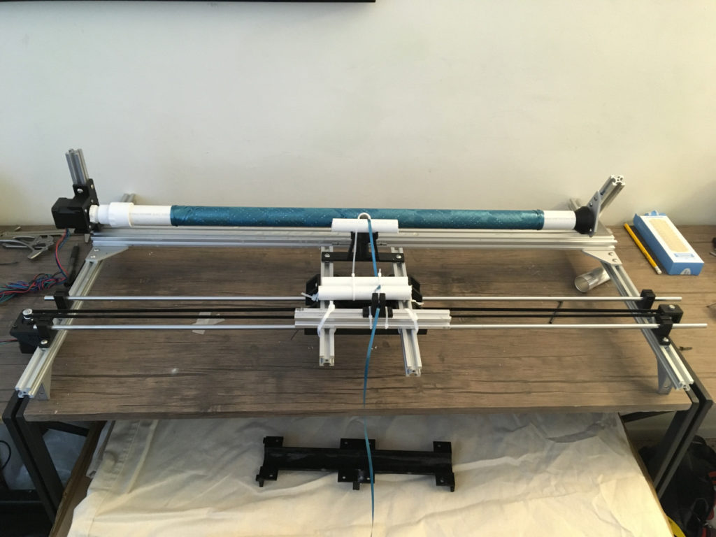
The overall bike build is shown here, which necessitated him designing a variety of jigs, including a CNC wrapping machine.
His device uses an Arduino Uno, along with a pair of driver boards, to carefully roll strands of carbon fiber on a PVC mandrel in an overlapping pattern. Epoxy was dripped on the assembly during the process, resulting in CF rods that were lighter and much cheaper than purchased rods.
After quite a bit more work assembling everything together, Kevan now has a bike frame that is truly made to his specs!
Seating charts at weddings and other formal events are usually handled by small cards at each table, but Gabrielle Martinfortier had other plans.
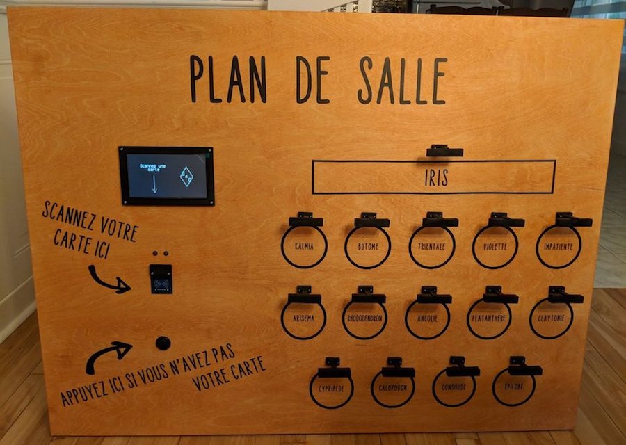
For her big event, she along with help from her now-husband and friends constructed a seating arrangement on a 3’ x 4’ wood canvas, equipped with a 7” TFT display and an RFID reader. An Arduino Mega serves as the brains of the device, taking advantage of its expanded IO capabilities to control an LED assembly over each table on the chart.
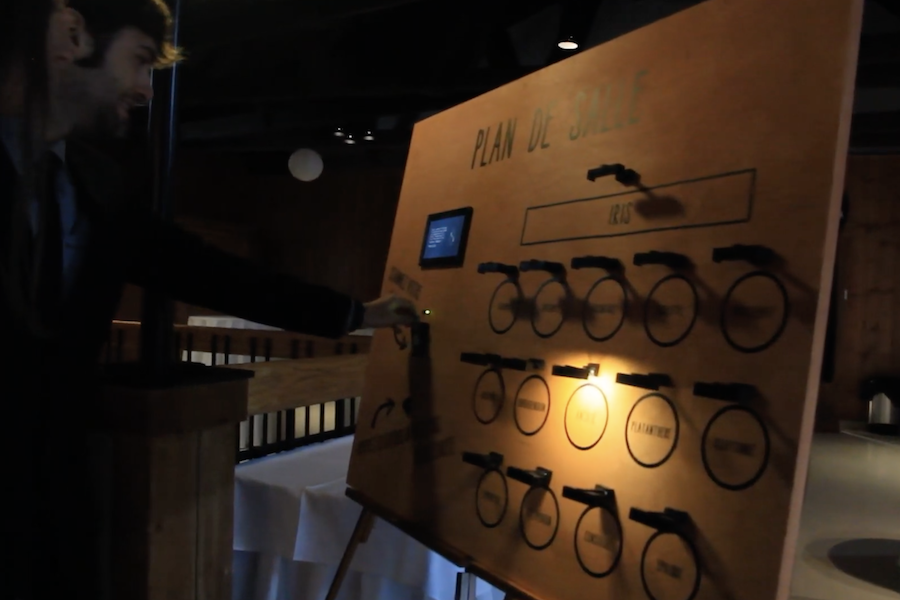
Wedding guests simply had to present the card they received with the invitation, then their proper table was lit. As seen in the video below, this eliminated seating confusion, and provided a bit of extra entertainment for those involved.
I wanted to make something special for my wedding tables chart, and I thought this was a good way of making it personal, as it reflects my love (addiction) for electronic projects.
So the plan was to make a big wood panel with the plan of the room on it, including, of course, the tables and their names (they are plant names, in French). The guests received a card with an RFID sticker on it along with their invitation. On the back of the card was written (in French) something like “This card is of great importance, keep it safe and carry it on you at the wedding.” I didn’t want them to know what it was for until the wedding.
The chart has several elements a TFT display, an RFID reader, a green LED and a red LED, a push button and one strip of 3 LEDs for each table. When the RFID tags are scanned, the green LED turns on if it is recognized, and a personalized message is displayed on the screen, including the name of the table where the guest is seated. In addition, the LED strip associated with the table is turned on, shedding light on the table on the room’s plan. If the card is misread or unrecognized, the red LED is turned on with an “access denied” message on the screen. The button is for those who did not succeed in not losing or forgetting the card. It displays a message on the screen, asking them to go to the bar and say something like “I am not reliable,” in exchange of which they get a backup chart to find their seat.
I changed a few things along the way: I wanted to paint the wood panel but changed my mind because I was scared I’d make a mess and have to start over with a new panel. Since I have a circuit machine I decided to make the writings and drawings with vinyl.
I also had a 20×04 character LCD screen in the beginning, but I upgraded to a 7″ TFT screen because it’s bigger and not as limiting in terms of message length.
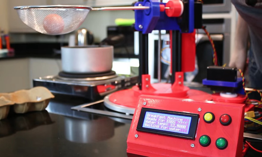
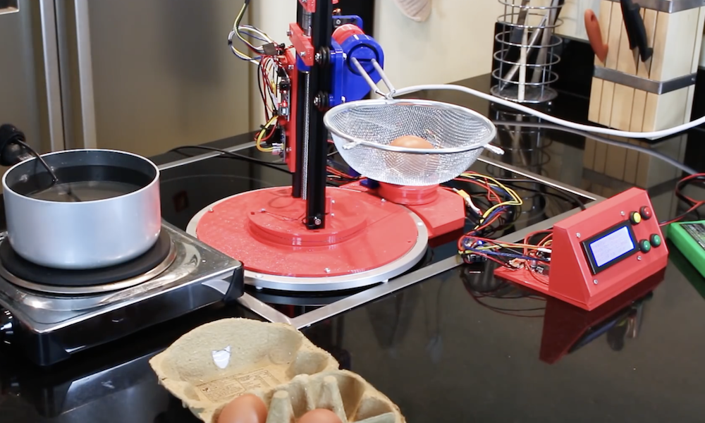
Normally, boiling an egg involves heating water in a saucepan, then dropping an egg inside to be properly heated. James Bruton, however, now has a bit of help in the form of his breakfast-making robot.
The device uses two servos, along with a motor/encoder/screw assembly to rotate and lower the egg into place. It then takes it out after six minutes, and tips it out into a secondary container.
As of now, temperature is manually controlled, but it’s tracked with a DS18B20 temperature sensor to initiate the egg lowering procedure. An Arduino Uno takes care of the lifting screw assembly, while an Arduino Mega handles everything else.
After letting his Arduino languish in a drawer for some time, Brandon Switzer decided to take it out and start experimenting. While he could have started off small, Switzer chose to instead create his own player piano system, completing it at a cost of around $650.
While the details of the project aren’t explicitly spelled out, you can see a time-lapse of this amazing build in the video below. As you can imagine, it took a massive amount of breadboard space to get all the electronics laid out, and a similarly impressive number of solenoids to activate all of the keys.
Additionally, he had to do plenty of mechanical work, including the cringeworthy job of actually drilling into a what appears to be a functional piano!
In early August 2017 I was looking to partake in some kind of engineering project that would be fun and also help me learn new things. For a long time I had an Arduino Uno that had been sitting in a drawer, and for the first time I took it out to experiment with it and create something new.
For a long time I had been inspired by player pianos — it’s something about the way the keys move on their own that make them so wonderful. I wanted to create something like that — something that didn’t only work but also impressed the viewer — for a cheap cost.
One of my goals in creating this was to show that it’s possible to replicate amazing things for little money, and I think I proved this. While a player system from Yamaha or Pianodisc cost upwards of $10,000, I built my own system for a measly $650. Not only that, but once you buy your $10,000 player piano, you have to purchase extra apps and songs if you actually want to play something on it. Overall I’m very satisfied with the way the piano turned out, and I’m excited to use it in the future.
The field of radio control has benefited much from the onward march of technology. Where a basic 2-channel setup would once have cost hundreds of dollars, it’s now possible to get a high-end 2.4GHz 9-channel rig for well under $100, shipped to your door. However, the vast majority of these systems are closed-source and built for purpose. Sometimes, there are benefits to doing things your own way, and that’s precisely what this project does.
At its heart, it’s a simple combination. An Arduino Pro Mini talks to a NRF24L01 which handles the wireless communication. At that point, it’s up to you – throw in as few or as many controls as you like. For this build, [HowToMechatronics] has gone with a twin-stick setup, with a pair of potentiometers and twin toggle switches to round out the options.
The build comes in handy, as it’s possible to program in whatever features you may need for a given project. [HowToMechatronics] has used it to control a hexapod robot, among other projects. It’s a build that shows that with cheap and readily available parts, it’s possible to whip up a custom solution to suit your needs.
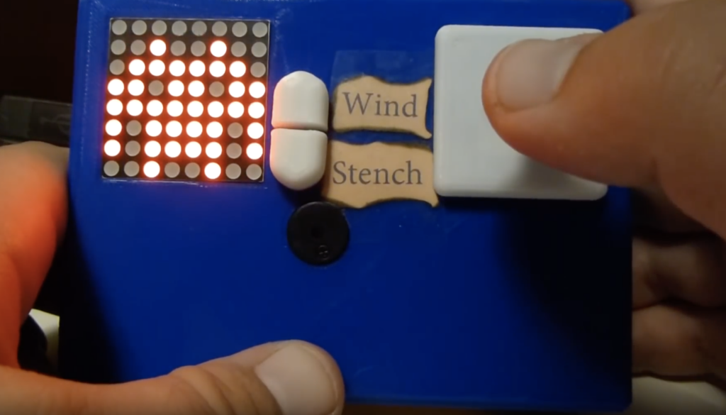
Hunt the Wumpus is a text-based survival/horror game developed in 1973. As such, it’s perhaps due for an update, and Benjamin C. Faure was able to do so using an Arduino Mega to run a graphical version on an 8×8 MAX7219 LED display.
The game consists of moving your character through the 64-LED randomly generated world, avoiding pits and bats, attempting to face the Wumpus to fire your one arrow. Navigation is aided by “wind” and “stench” lights, indicating either a pit or the foul Wumpus is nearby. The game is also enhanced with a few LED animations and a small piezo speaker.
On startup, the game will generate an 8×8 map for the player that contains bats, pits, and a Wumpus. The player must pay attention to their senses to ensure they don’t fall into a pit or run into a Wumpus. Running into a bat might not be instant death, but they can carry you over a pit or even straight to the Wumpus.
If the player wishes to win, they must pinpoint the location of the Wumpus. Then, they must take one step towards the Wumpus (so that they are facing the proper direction) and fire their only arrow. If they hit the Wumpus, they win! If they miscalculated, however, they will meet a grisly fate.
A demo can be seen below, while code for the project is available on GitHub.
Glue sticks are great for attaching electronics and other bits to projects, but as Jon Bumstead shows in his latest work, they can also make pretty cool light diffusers.
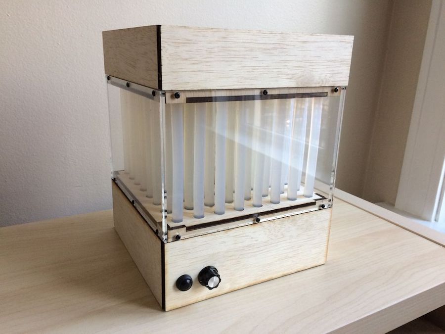
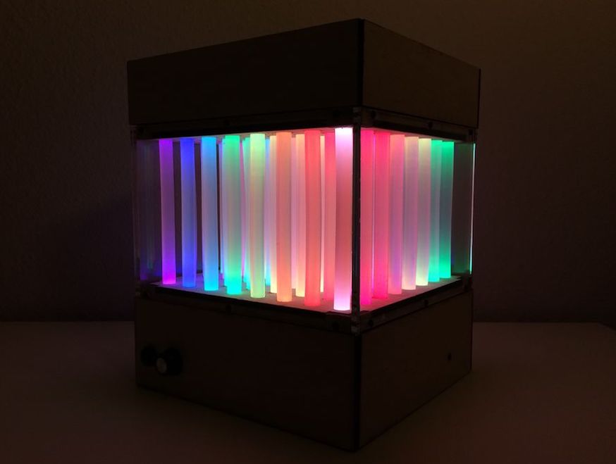
His project takes the form of a wooden box with plexiglass panels, allowing observers to see 64 vertical illuminated glue sticks inside. Hidden within the cube are 128 WS2811 LED modules, melted into the top and bottom of each stick.
Everything is built around an Arduino Nano, using only a pair of its outputs to control each LED. User interface is provided by a button and knob to adjust speed, color, and patterns.
In this project, I created a “fiber optic” LED matrix using WS2801 LED strip and glue sticks. The light displays have a different look than similar LED cubes and a few advantages. First, you can’t see the actual LEDs in the display because the glue sticks guide the light away from the LEDs. Second, the device requires much fewer LEDs to make up the volume. Because the top and bottom have different LED strips, the fiber optic cables can take on two different colors that mix in the center. There are tons of different color displays that can be achieved with the device. I also added a button and knob for controlling the speed, color, and type of light display.
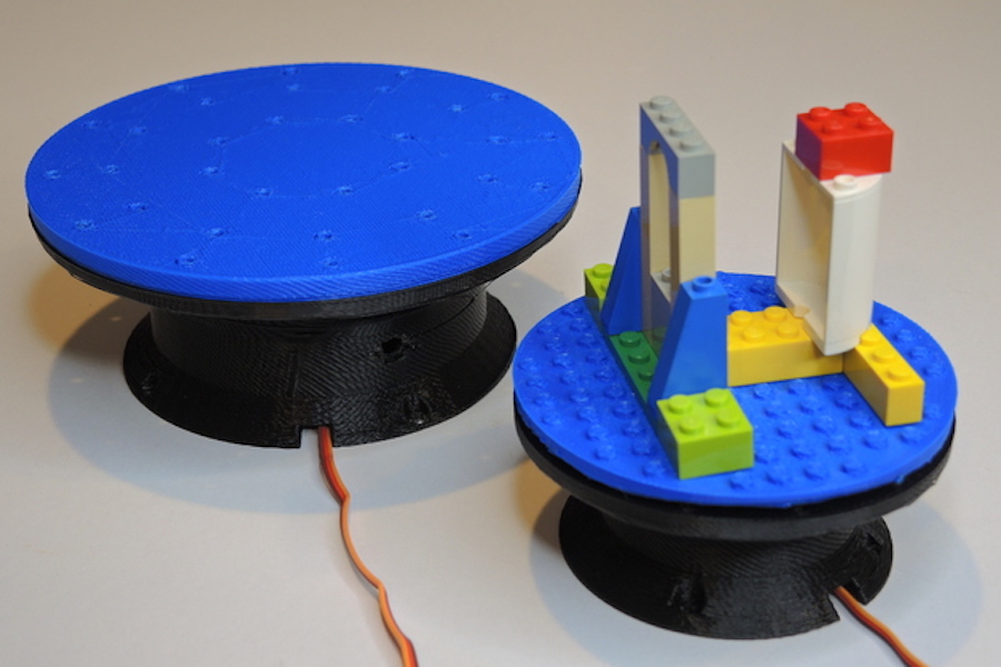
If you need a motorized turntable for filming or simply to display your latest project, here’s an easy 3D-printable option from Ali of Potent Printables.
The design takes two forms—one using a full-sized hobby servo, and a smaller version that employs a micro servo for motion, both of which are set up for continuous rotation.
Electronics for the project are fairly straightforward, with an Arduino Uno powering the tables via an Adafruit Motor Shield. While this could be expanded for different I/O or sensor use, the clever bit of this configuration is its interchangeable design. A master circle is connected to the servo horn, while the swappable plates attach to it with magnets, accommodating a flat surface, mounting holes, or even LEGO bricks.
Way back when, before diesel-electric locomotives were a thing, trains weren’t really able to go backwards too well. Also it’s sometimes necessary to turn carriages around in a small space. For that, the railway turntable was invented. If you want to implement one on a model layout, this project from DIY & Digital Railworld is for you.
The project is at an early stage – thus far, laying out how to set up an Arduino Uno using a potentiometer to control the speed of a stepper motor, which rotates the turntable. The turntable itself is a 3D printed part sourced from Thingiverse, designed to suit the specific stepper motor used.
This has the easy part sorted – rotating a piece of track through 360 degrees to orient a train properly. However, there’s significant work ahead. Power needs to be hooked up to the rails, and a system for accurately aligning the turntable with outgoing tracks needs to be devised. This is particularly relevant for N-gauge setups, where tolerances are everything.
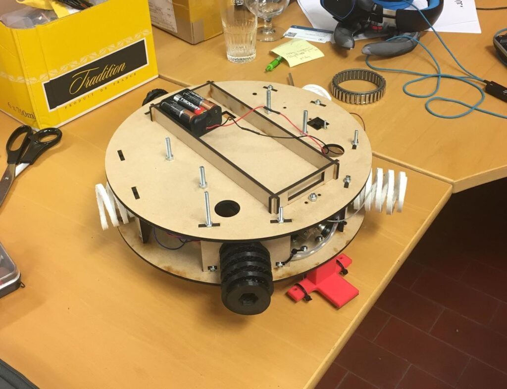
If you’ve ever been to an escape room, you’ve undoubtedly had to deal with a wide variety of puzzles that you have to solve in order to get out of the “prison” that you’ve willingly thrown yourself into. Beyond the puzzle that you’re trying to decode, the mechanisms used can be extremely clever, and coming up with a new device to use in these scenarios was a perfect challenge for this team of Belgian college students.
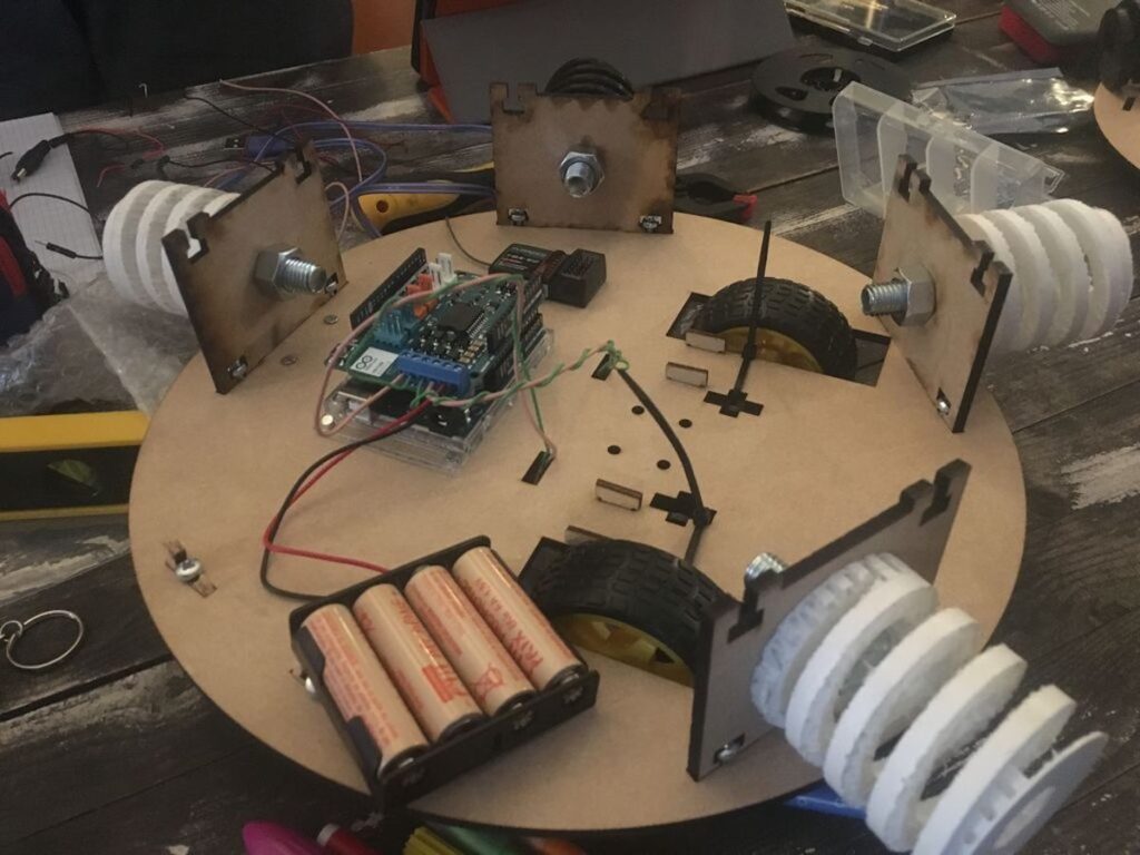
Based on the project requirements, they created a Roomba-like circular robot controlled by an Arduino Uno and motor shield that drives a pair of DC motors. The idea, while not fully implemented due to time constraints, is that it can be remotely operated only after solving a riddle and within a certain time period, then drive itself back to a designated spot once the game is over.
Here is a summary of what happens in the robot:
– The non-autonomous part: a remote controller is linked to Arduino through a receiver. Players control the remote and therefore control the Arduino which controls the motors. The Arduino is turned on before the game starts, but it enters the main function when players solve a riddle on the remote controller. An IR wireless camera is already turned on (turned on at the same time as the “whole” (controlled by the Arduino) when switch on/off turned on). Players guide the car with remote controller: they control the speed and the direction. When the timer that starts when the main function is entered is equal to 30 minutes, the control from the controller is disabled.
– The autonomous part: the control is then managed by the Arduino. After 30 minutes, the IR line tracker sensor starts following a line on the ground to finish the parcours.