Posts with «arduino uno» label

Driving a Controllerless LCD With the Humble Arduino Uno

These days, you could be forgiven for thinking driving an LCD from a microcontroller is easy. Cheap displays have proliferated, ready to go on breakout boards with controllers already baked in. Load up the right libraries and you’re up and running in a matter of minutes. However, turn your attention to trying to drive a random LCD you’ve yanked out of a piece of old equipment, and suddenly things get harder. [Ivan Kostoski] was in just such a position and decided to get down to work.

[Ivan]’s LCD was a 320×240 STN device salvaged from an old tape library. The display featured no onboard controller, and the original driver wasn’t easily repurposed. Instead, [Ivan] decided to drive it directly from an Arduino Uno.

This is easier said than done. There are stringent timing requirements that push the limits of the 8-bit platform, let alone the need for a negative voltage to drive the screen and further hardware to drive the backlight. These are all tackled in turn, with [Ivan] sharing his tips to get the most flexibility out of the display. Graphics and text modes are discussed, along with optimizations that could be possible through the varied use of available RAM and flash.

The code is available on Github. If you need inspiration for your own controllerless LCD driver. [Ben Heck] has done similar work too, using FPGA grunt to get the job done.

ESP-13 WiFi Shield Web Server

Description

This tutorial will show you how to setup a simple webserver on your ESP-13 WiFi Shield and display a table of all of the WiFi Access Points within it's range (and refreshed every 5 seconds).
The ESP-13 shield will create it's own WiFi access point, which means that you can take this project anywhere you want to. You do not have to be connected to your home/work WiFi network to see the webpage. The limitation however, is that your device must be within WiFi range of the ESP-13 WiFi shield in order to see the results of the WiFi scan.

Let me show you how to put this project together:
COMING SOON....

ScottC 16 Sep 18:13

Getting Started with the Keyes ESP-13 WiFi Shield

Description

This tutorial will help you get started with the KEYES ESP-13 WiFi Shield.

The ESP-13 WiFi Shield is compatible with an Arduino UNO and has the same form-factor. Essentially this shield will give your Arduino project WiFi capabilities. While it interfaces nicely with the Arduino, it can operate without it. However, if I were planning on using the shield independantly, then I probably would opt for an ESP module rather than a shield.

I bought my shield from Jaycar (CAT.NO: XC4614), however you can get it much cheaper from other online retailers at about a quarter of the price. The instructions on the Jaycar website are not that good, and at first I thought I had bought myself a useless product. It just didn't seem to work regardless of what I tried. There were some tutorials online that gave me hope, only to find that my shield was not quite the same and therefore I did not get the same results. But after countless hours of trial and error and patching various bits of knowledge together, I finally worked out how to use this shield. Everything has fallen into place. And it is easier that you would think... let me show you how.

Parts Required

  1. Arduino UNO (or compatible board)
  2. KEYES ESP-13 WiFi Shield - from Jaycar (Cat. No: XC4614)
  3. USB cable - to connect Arduino to Computer
  4. 4 wires: 4 x Male to Male connectors


Libraries and IDE

Arduino IDE

While there are many Arduino IDE alternatives out there, I would recommend that you use the official Arduino IDE for this project. I used the official Arduino IDE app (v1.8.5) for Windows 10.
Make sure to get the most up-to-date version for your operating system here.


Upload BareMinimum Sketch

Upload a BareMinimum Sketch to the Arduino UNO (or compatible board) before making any connections to the ESP-13. We want to upload the BareMinimum sketch because we don't want the Arduino UNO interfering with our setup in anyway. Here is how to do that:

  1. Start your Arduino IDE
  2. Connect the Arduino UNO to the Computer using a USB cable
  3. Select: File > New (or Ctrl + N)
  4. Select: File > Examples > 01.Basics > BareMinimum
  5. Select: Tools > Board > Arduino/Genuino UNO
  6. Select: Tools > Port > COM4 (Your Arduino may be on a different COM port)
  7. Select: Sketch > Upload (or Ctrl + U) - or click on right arrow symbol
  8. After the sketch has uploded. Disconnect the USB cable from the computer/Arduino.


IDE Configuration for ESP-13

Now for the fun part. The ESP-13 WiFi Shield is itself a microcontroller, however, the Arduino IDE is not by default, configured to communicate with or program the ESP-13 WiFi Shield. We are about to change that:

  1. Select File > Preferences from the Arduino IDE menu (or Ctrl+Comma)
  2. Insert the following text into the Additional Boards Manager URLs field:
    If there is a URL in that space already, then insert a comma, and append the URL to the end:

    http://arduino.esp8266.com/stable/package_esp8266com_index.json


  3. Once the URL is added, press OK.
    This will allow us to install the ESP8266 package in the next step.


Installing the ESP8266 board

  1. Select: Tools > Board: "xxxx" > Boards Manager
  2. Search for ESP8266 using the Search bar
  3. Select the "esp8266 by ESP8266 Community" board from the list.
  4. Select the latest or most up-to-date version from the drop-down box (eg. 2.4.2)
  5. Press the Install button.
  6. Make sure that the esp8266 board is installed. Then press the "Close" button
  7. Choose the ESPDuino(ESP-13 Module) from the ESP8266 Modules list:
    Tools > Board: "xxxx" > ESPDuino(ESP-13 Module)


ESP-13 Flash Settings

You will then want to check that you have the following settings in the Tools menu of the Arduino IDE:

  • Board: "ESPDuino (ESP-13 Module)"
  • Flash Size: "4M (1M SPIFFS)"
  • Debug port: "Disabled"
  • Debug Level: "None"
  • IwIP Variant: "v2 Lower Memory"
  • Reset Method: "ESPduino-V2"
  • VTables: "Flash"
  • CPU Frequency: "80MHz"
  • Upload Speed: "115200"
  • Erase Flash: Only Sketch
  • Port: - (we will select that later)

The Arduino IDE is now able to communicate with, and program the ESP-13 WiFi shield.
Now let us have a look at how to use the default AI-Thinker AT-firmware that comes pre-loaded on the shield.


Preparing the WiFi Shield for Communication

The Keyes ESP-13 WiFi shield comes pre-loaded with AI-Thinker firmware. I thought I just had to place the WiFi shield on top of the Arduino UNO, and I should be able to send through some AT commands via the Serial monitor. Yes - it is a shield, and yes, we will use it as a shield later on, but if you want to use the Serial monitor while the shield is sitting on-top of the Arduino UNO, you will need to make use of the SoftwareSerial library. You can go down this path, but it is cumbersome. There is a better way. We will still need the Arduino UNO, but we need to connect it to the ESP-13 Shield in the following manner:

Wire Connections

  1. Make sure that the Arduino UNO is OFF (i.e. not connected to power or USB port)
  2. Place the ESP-13 WiFi shield NEXT TO the Arduino UNO
  3. Connect a Red wire between 5V on Arduino UNO, and 5V (Arduino side) of the ESP-13 shield
  4. Connect a Black wire between GND on Arduino, and G (Arduino side) of the ESP-13 shield
  5. Connect a Green wire between D0(RX) on Arduino, and TX (UART - Arduino side) of ESP-13
  6. Connect a Yellow wire between D1(TX) on Arduino, and RX (UART - Arduino side) of ESP-13
  7. Make sure that both of the switches on the ESP-13 WiFi Shield are in the "ON" position.

Serial Monitor Setup

  1. Plug the USB cable into the computer, and the other end into the Arduino
  2. You should see a Red LED ignite on the ESP-13 Shield.
  3. In your Arduino IDE, make sure the correct COM port is selected:
    Tools > Port > COM4 (Arduino/Genuino UNO) - your port may be different.
  4. The IDE recognises that an Arduino is using that COM port, even though ESP-13 Board selected
  5. Open the Serial Monitor: Tools > Serial Monitor (or Ctrl + Shift + M)
  6. Select: Both NL & CR from the drop-down box at the bottom right side of the Serial Monitor.
  7. Select: 115200 baud from the other drop-down box in the Serial Monitor window.
  8. Press the RESET (RST) button on the bottom left of the ESP-13 WiFi Shield.
  9. You may see some garbled information come through, but you should see "Ai-Thinker Technology Co.,Ltd" and "ready" messages in the debug window.
  10. You can now send through your AT-commands to the ESP-13 WiFi shield.


Using default AI-Thinker AT-firmware

Now is a good time to test the AI-Thinker AT-firmware. It is possible to program the Arduino to send a sequence of AT commands to the ESP-13 WiFi Shield, but for demonstration purposes, I will show you how to send the commands manually via the Serial monitor.

  1. If you see "ready" within the Serial Monitor window, the ESP-13 is ready to receive AT commands.
  2. Type: AT into the box at the top and press the Send button (or Enter)
  3. You should now see the AT command in the debug window, and a response "OK"

If you received the OK message, then your communication with the ESP-13 was successful.
A good list of AT commands and explanations can be found here.
Another list of AT commands can be found here.

The commands allow you to test, query and configure the ESP-13 shield. Essentially a command-line interface. Try out the following commands to get a feel for these functions/queries. The commands are in bold, and I placed some of the responses that I got in the line below.

  1. AT
    Response: OK

  2. AT+RST
    This resets the ESP-13 board. It provides some info about the board.

  3. AT+GMR
    AT version: 0.40.0.0 (Aug 8 2015)
    SDK version: 1.3.0
    Ai-Thinker Technology Co.,Ltd.
    Build:1.3.0.2 Sep 11 2015

  4. AT+CIFSR
    +CIFSR:APIP, "192.168.4.1"

  5. AT+CWMODE?
    +CWMODE:2 [1=STA, 2=AP, 3=BOTH]

  6. AT+CWLAP
    ERROR

  7. AT+CWMODE=3

  8. AT+CWLAP
    +CWLAP:(3,"MYACCESSPOINT", -53, "xx:xx:xx:xx:xx:xx",6,-12)

So there you go. Now you have everything need to configure your ESP-13 WiFi shield. Once you are tired of playing around with AT commands, I will show you how to re-program and upload sketches to the ESP-13 WiFi Shield, and use it the way it was designed to be used (i.e. as a shield). To upload sketches to the Shield, you will need one extra wire. But I think that deserves to be another tutorial. Stay tuned.

Summary

In this tutorial, I showed you how to configure your Arduino IDE for the ESP-13 shield. I also explained how to wire the ESP-13 WiFi shield so that you can communicate with it using the Serial monitor. I hope this tutorial helped you in some way. If it did, please let me know in the comments below. I will be following up with another tutorial, which will show you how to upload sketches to the ESP-13 WiFi Shield, and free it from your computer.


Social Media

You can find me on various social networks:


Visit my ArduinoBasics Google + page.
Follow me on Twitter by looking for ScottC @ArduinoBasics.
I can also be found on Pinterest and Instagram.
Have a look at my videos on my YouTube channel.


Getting Started with the Keyes ESP-13 WiFi Shield

Description

This tutorial will help you get started with the KEYES ESP-13 WiFi Shield.
The ESP-13 WiFi Shield is compatible with an Arduino UNO and has the same form-factor. Essentially this shield will give your Arduino project WiFi capabilities. While it interfaces nicely with the Arduino, it can operate without it. However, if I were planning on using the shield independantly, then I probably would opt for an ESP module rather than a shield.
I bought my shield from Jaycar (CAT.NO: XC4614), however you can get it much cheaper from other online retailers at about a quarter of the price. The instructions on the Jaycar website are not that good, and at first I thought I had bought myself a useless product. It just didn't seem to work regardless of what I tried. There were some tutorials online that gave me hope, only to find that my shield was not quite the same and therefore I did not get the same results. But after countless hours of trial and error and patching various bits of knowledge together, I finally worked out how to use this shield. Everything has fallen into place. And it is easier that you would think... let me show you how.


Coming soon......................

Feed Barbie with the J’ai faim! mechatronic game

According to this project’s write-up, while some struggle to get enough nourishment, those in more developed countries often aspire to consume too little food. As an apparent commentary on this situation, Niklas Roy and Kati Hyyppä have created a mechatronic game called J’ai faim!, French for “I’m hungry!”

In this Arduino-controlled game, participants rotate a Barbie head to point her comically over-sized tongue over a piece of sushi lit up by an LED. When in position, the player fires her solenoid-actuated tongue using the joystick, and if the correct sushi is eaten the score progresses from “starving” to “well fed.” 

You can see the game—reminiscent of a very strange version of whack-a-mole—in the video below.

Notable Board Books are an Arduino-powered way to enjoy music

Annelle Rigsby found that her mother, who suffers from Alzheimer’s, is delighted to hear familiar songs. While Annelle can’t always be there to help her enjoy music, she and her husband Mike came up with what they call the Notable Board Book that automatically plays tunes.

The book itself is well laid-out, with song text and familiar photos printed on the pages. Electronics for the book are in a prototype state using an Arduino Uno and an Adafruit Sound Board to store and replay the audio bits.

Page detection is handled by an array of photocells, and it is meant to turn on automatically when picked up via a series of tilt switches. When a switch is triggered, a relay can then hold the book on until the song that is playing is done, or for a predetermined amount of time.

Arduino Just Introduced an FPGA Board, Announces Debugging and Better Software

Today ahead of the Bay Area Maker Faire, Arduino has announced a bevy of new boards that bring modern features and modern chips to the Arduino ecosystem.

Most ambitious of these new offerings is a board that combines a fast ARM microcontroller, WiFi, Bluetooth, and an FPGA. All this is wrapped in a package that provides Mini HDMI out and pins for a PCIe-Express slot. They’re calling it the Arduino MKR Vidor 4000.

Bringing an FPGA to the Arduino ecosystem is on the list of the most interesting advances in DIY electronics in recent memory, and there’s a lot to unpack here. FPGA development boards aren’t new. You can find crates of them hidden in the storage closet of any University’s electronics lab. If you want to buy an FPGA dev board, the Terasic DE10 is a good starter bundle, the iCEstick has an Open Source toolchain, and this one has pink soldermask. With the release of the MKR Vidor, the goal for Arduino isn’t just to release a board with an FPGA; the goal is to release a tool that allows anyone to use an FPGA.

The key to democratizing FPGA development is Arduino’s work with the Arduino Create ecosystem. Arduino Create is the company’s online IDE that gives everyone the ability to share projects and upload code with Over-the-Air updates. The MKR Vidor will launch with integration to the Arduino Create ecosystem that includes a visual editor to work with the pre-compiled IP for the FPGA. That’s not to say you can’t just plug your own VHDL into this board and get it working; that’s still possible. But Arduino would like to create a system where anyone can move blocks of IP around with a tool that’s easy for beginners.

A Facelift for the Uno WiFi

First up is the brand new Arduino Uno WiFi. While there have been other boards bearing the name ‘Arduino Uno WiFi’ over the years, a lot has changed in the world of tiny radio modules and 8-bit microcontrollers over the past few years. The new Arduino Uno WiFi is powered by a new 8-bit AVR, the ATMega4809. The ATMega4809 is a new part announced just a few months ago, and is just about what you would expect from the next-generation 8-bit Arduino; it runs at 20MHz, has 48 kB of Flash, 6 kB of SRAM, and it comes in a 48-pin package. The ATMega4809 is taking a few lattices of silicon out of Microchip’s playbook and adds Custom Configurable Logic. The CCL in the new ATMega is a peripheral that is kinda, sorta like a CPLD on chip. If you’ve ever had something that could be more easily done with logic gates than software, the CCL is the tool for the job.

But a new 8-bit microcontroller doesn’t make a WiFi-enabled Arduino. The wireless power behind the new Arduino comes from a custom ESP-32 based module from u-blox. There’s also a tiny crypto chip (Microchip’s ATECC508A) so the Uno WiFi will work with AWS. The Arduino Uno WiFi will be available this June.

But this isn’t the only announcement from the Arduino org today. They’ve been hard at work on some killer features for a while now, and now they’re finally ready for release. What’s the big news? Debuggers. Real debuggers for the Arduino that are easy to use. There are also new boards aimed at Arduino’s IoT strategy.

The Future of Arduino

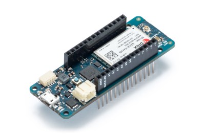
As you would expect in the world of embedded development, the future is IoT. Last week, Arduino announced the release of two new boards, the MKR WiFi 1010 and the MKR NB 1500. The MKR WiFi 1010 features a SAMD21 Cortex-M0+ microcontroller and a u-blox module (again featuring an ESP-32) giving the board WiFi. The MKR NB 1500 is designed for cellular networks and features the same SAMD21 Cortex-M0+ microcontroller found in the MKR WiFi 1010, but also adds a u-blox cellular module that will connect to LTE networks using Narrowband IoT, but the module does also support Cat M1 networks.

But IoT isn’t the only thing Arduino has been working on. On the leadup to the World Maker Faire this weekend, I had the opportunity to speak with Fabio Violante, CEO of Arduino, and Massimo Banzi, Co-founder of Arduino, and what I heard was remarkable. There’s going to be an update to the Arduino IDE soon, and real debugging is coming to the Arduino ecosystem. This is a significant development in Arduino’s software efforts, and when Fabio was appointed CEO last July, this was the first thing he wanted to do.

Also on deck for upcoming bits of hardware is a slow upgrade from ARM Cortex-M0 parts to Cortex-M4 parts. While this change isn’t exactly overdue, it is a direct result of the ever-increasing power of available microcontrollers. The reason for this change is the growing need for more compute power on embedded platforms, and simply the fact that more powerful chips are cheaper now.

Massimo, Fabio, and the rest of the Arduino team will be showing off their latest wares at Maker Faire Bay Area this weekend, and we will be posting updates. The FPGA Arduino — the MKR Vidor 4000 — will be on display running a computer vision demo, and there will, of course, be fancy new boards on hand. We’ll be posting updates so keep your eye on Hackaday!

Hack a Day 18 May 16:03

Tracktorino Shields You From Poor Interfaces

On-screen controls in a digital audio workstation expand the power of a DJ or musician, but they are not intuitive for everyone. The tactility of buttons, knobs, sliders and real-world controls feels nothing like using a mouse, trackpad, or even a touchscreen. Unfortunately, devices meant to put control into a DJs hands can be unavailable due to location or cost. [Gustavo Silveira] took charge of the situation so he could help other DJs and musicians take control of their workstations with a customized MIDI interface for Traktor DJ software.

MIDI is a widely used serial protocol which has evolved from a DIN connector to USB, and now it is also wireless. This means that the Traktorino is not locked to Traktor despite the namesake. On the Hackaday.io page, there’s even a list of other workstations it will work with, but since many workstations, all the good ones anyway, accept MIDI hardware like this, the real list is a lot longer.

The custom circuit board is actually a shield. Using an Arduino UNO, the current poster child of the Arduino world, opens up the accessibility for many people who don’t know specialized software. A vector drawing for a lasercut enclosure is also included. This means that even the labeling on the buttons are not locked into English language.

Here’s another project which combined laser cutting and MIDI to make some very clever buttons or turn your DIN MIDI connector into USB.

Turtlebyte

Primary image

What does it do?

Autonomous robot pet

3/6/18- Just finished the front legs! Woohoo! I did several test runs on one of them, the most recent being documented in the video. But I screwed up the movement range in the test Arduino sketches, since the servos can no longer rotate fully. I hope I didn’t strain the servo too bad...

————————————————————

Cost to build

Embedded video

Finished project

Number

Time to build

Type

legs

URL to more information

Weight

read more

Vintage Sewing Machine to Computerized Embroidery Machine

It is February of 2018. Do you remember what you were doing in December of 2012? If you’re [juppiter], you were starting your CNC Embroidery Machine which would not be completed for more than half of a decade. Results speak for themselves, but this may be the last time we see a first-generation Raspberry Pi without calling it retro.

The heart of the build is a vintage Borletti sewing machine, and if you like machinery porn, you’re going to enjoy the video after the break. The brains of the machine are an Arduino UNO filled with GRBL goodness and the Pi which is running CherryPy. For muscles, there are three Postep25 stepper drivers and corresponding NEMA 17 stepper motors.

The first two axes are for an X-Y table responsible for moving the fabric through the machine. The third axis is the flywheel. The rigidity of the fabric frame comes from its brass construction which may have been soldered at the kitchen table and supervised by a big orange cat. A rigid frame is the first ingredient in reliable results, but belt tension can’t be understated. His belt tensioning trick may not be new to you, but it was new to some of us. Italian translation may be necessary.

The skills brought together for this build were vast. There was structural soldering, part machining, a microcontroller, and motion control. The first time we heard from [juppiter] was December 2012, and it was the result of a Portable CNC Mill which likely had some influence on this creation. Between then, he also shared his quarter-gobbling arcade cabinet with us.