Posts with «arduino shield» label

Brushless Motor Controller Shield for Arduino

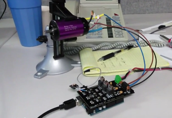
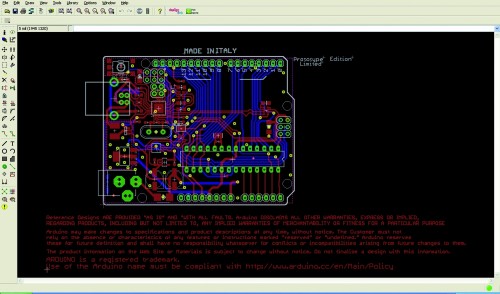
Brushless motors are ubiquitous in RC applications and robotics, but are usually driven with low-cost motor controllers that have to be controlled with RC-style PWM signals and don’t allow for much customization. While there are a couple of open-source brushless drivers already available, [neuromancer2701] created his own brushless motor controller on an Arduino shield.

[neuromancer2701]‘s shield is a sensorless design, which means it uses the back-EMF of the motor for feedback rather than hall effect sensors mounted on the motor. It may seem strange to leave those sensors unused but this allows for less expensive sensorless motors to work with the system. It also uses discrete FETs instead of integrated driver ICs, similar to other designs we have covered. Although he is still working on the back-EMF sensing in his firmware, the shield successfully drives a motor in open-loop mode.

The motor controller is commanded over the Arduino’s serial interface, and will support a serial interface to ROS (Robot Operating System) in the future. This shield could be a good alternative to hobby RC controllers for robots that need a customizable open-source motor controller. The PCB design and source code are available on GitHub.


Filed under: Arduino Hacks

Arduino DMX shield for Christmas projects

.


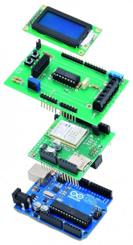
This shield allows to connect an Arduino with DMX equipment. It implements the RS485 interface to adapt the electrical levels needed for DMX connection.

This shield has been designed with flexibility in mind and allows the user to choose between several Arduino pins for digital input and output of DMX data, it supports a microSD slot and also has the serial connection to support a serial LCD display.

This design allows basic operation of DMX through simple pre programmed messages stored in the Arduino Sketch or, with the proper libraries and programming, it could well become a standalone system with playback capabilities of sequences stored on the microSD. When needed, this solution is also a suitable interface for a PC sending through a serial port the DMX commands.

DMX basics

This interfacing and communication standard has been developed to allow easier management of complex lighting systems. On stages and discos, many spots, pars, moving heads and other equipment need to be managed and controlled, but bringing power from a centralized panel rises many issues for safety and cabling complexity.

With DMX, each device has an integrated or external controller. A control system sends a specific message to each controller with a byte that the controller itself interprets according to its address and capabilities. Power supply becomes “local” and the communication is with a daisy chained cable that carries low voltage signals.

DMX data is sent in parallel to every controller connected and the address given to each controller allows each device to grab and interpret only the relevant information.

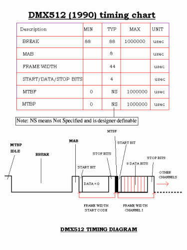
The transmission scheme has been designed for efficiency as DMX may drive up to 512 devices at the same time, with 40 complete transmission sets per second. To achieve this, with 8 bits, 1 start and 1 stop bit, speed has to be 250 kbps. The serial data starts with a header and then bytes are sent in sequence, starting from the first one.

If we have to send a new command to the controller with address 10, we need to send also the data relevant to the controllers from 1 to 9. The addressing system is based on position of the byte and each controller counts the incoming bytes, discarding the ones preceding and following its own byte.

It is also important to remember that each command received is always relevant, therefore to alter the state of a single controller, it is necessary to send valid commands to all the controllers that have a lower address. The sequence, however, may end when the address of the relevant controller has been reached (no need to send the sequence with data exceeding the relevant controller address).

The values from 0 to 255 initially represented the level of the light (0 = off, 255 = full brightness), but the adoption of DMX by other devices turned the meaning of the byte into other commands, eg. position, program selection, specific preset, activate feature and so on. Each manufacturer specifies the mapping between values and functions and sometimes a single byte is not enough to manage all the capabilities, therefore the device occupies an interval of addresses on the DMX bus and reads more than one byte, in sequence.


Shield schematics

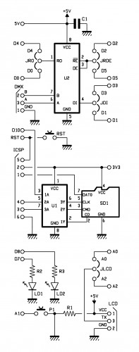
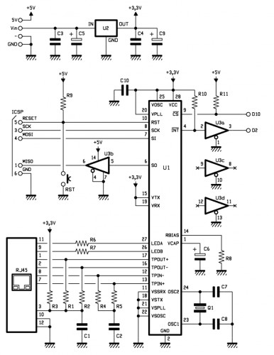
This shield uses a MAX485 by Maxim to convert the signal levels from the Arduino digital pin to the RS485 differential simplex two wire plus ground connection. The MAX485 contains a receiver and a transmitter, with enabling signals. The /RE (pin 2) and OE (pin 3) – that enable reception and transmission – are with inverted levels, so that it is possible to use a single line and the two pins connected together to manage transmission direction. Pin 1 is Receive Output, pin 4 is Data Input, pin 6 and 7 are the differential outputs.

It is possible to choose between different Arduino D pins for each of the three signals needed: RO may be mapped onto D0 or D4, DI onto D1 or D3 and /RE+OE onto D2 or D5.

The other chip on the shield is an 74HC4050D that contains six buffers to match TTL levels from Arduino ICSP with the 3,3V required by the microSD. This is required just by microSD input lines because Arduino input correctly reads the 3,3V level supplied by microSD as a logic “1”.

The last bits of the schematics include a couple of LEDs connected to D7 and D8, a pushbutton on A1 and the serial connection for the LCD on A0/A2 (jumper selectable).

Configuration

Before you proceed with this shield, you should decide the various jumpers positions; if no other shield is used with Arduino, you are free to choose any of the two positions available; when used with other shields, use the jumpers to avoid any conflict. Please note that ICSP is used with Ethernet shields as well, therefore the microSD slot might create conflicts if used with an Ethernet equipped solution.

DMX library 

DOWNLOAD DMX LIBRARY (Arduino1.0.1)

This shield needs a specific library named DmxSimple.h available for download at http://code.google.com/p/tinkerit/wiki/DmxSimple ; with it you will find some examples. We also have two other sketches to let you experiment with this shield.

/* Welcome to DmxSimple. This library allows you to control DMX stage and
** architectural lighting and visual effects easily from Arduino. DmxSimple
** is compatible with the Tinker.it! DMX shield and all known DIY Arduino
** DMX control circuits.
**
** DmxSimple is available from: http://code.google.com/p/tinkerit/
** Help and support: http://groups.google.com/group/dmxsimple       */

/* To use DmxSimple, you will need the following line. Arduino will
** auto-insert it if you select Sketch > Import Library > DmxSimple. 

Modified by Boris Landoni
open-electronics.org

*/

#include 

const int jrde =  2;
const int jdi  =  3;
const int jro  =  4;
const int lr   =  7;
const int ly   =  8;

void setup() {

  pinMode(jrde, OUTPUT);
  pinMode(jdi,  OUTPUT);
  pinMode(jro,  INPUT);
  pinMode(lr, OUTPUT);
  pinMode(ly, OUTPUT);

  digitalWrite(jrde, HIGH);

  /* The most common pin for DMX output is pin 3, which DmxSimple
  ** uses by default. If you need to change that, do it here. */
  DmxSimple.usePin(jdi);

  /* DMX devices typically need to receive a complete set of channels
  ** even if you only need to adjust the first channel. You can
  ** easily change the number of channels sent here. If you don't
  ** do this, DmxSimple will set the maximum channel number to the
  ** highest channel you DmxSimple.write() to. */
  DmxSimple.maxChannel(5);
}

void loop() {
  int brightness;
  /* Simple loop to ramp up brightness */  
  for (brightness = 0; brightness <= 255; brightness++) {
    digitalWrite(lr, HIGH);
    /* Update DMX channel 1 to new brightness */
    //DmxSimple.write(1, brightness);
    DmxSimple.write(2, brightness);
    //DmxSimple.write(3, brightness);
    DmxSimple.write(4, 189);

    /* Small delay to slow down the ramping */
    delay(10);
    digitalWrite(lr, LOW);
  }

}


Vixen


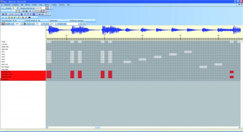
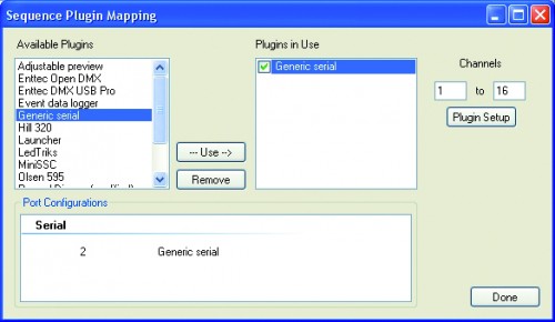
We also suggest to use Vixen (www.vixenlights.com) to create sequences on a PC, synced with music, that are sent to Arduino over the serial port. The communication between Arduino and Vixen is managed by our sketch DMX_LightSequencing.

/*
The purpose of this code is to allow the Arduino to use the 
generic serial output of vixen lights to control 5 channels of LEDs. 
Author: Matthew Strange
Created: 14 October 2010
Modifier: Ben Towner
Modified: 19-OCT-2010
Changes: Addition of 20 Digital On/Off Channels - Setup for Arduino Mega 2560
Modified by Boris Landoni
open-electronics.org

*/

#include 

const int jrde =  2;
const int jdi  =  3;
const int jro  =  4;
const int lr   =  7;
const int ly   =  8;

#define DELAY    10

int i = 0;     // Loop counter
int incomingByte[25];   // array to store the 25 values from the serial port
int address=1;
int ch=16;
int k;

//setup the pins/ inputs & outputs
void setup()
{
  Serial.begin(9600);        // set up Serial at 9600 bps

  pinMode(jrde, OUTPUT);
  pinMode(jdi,  OUTPUT);
  pinMode(jro,  INPUT);
  pinMode(lr, OUTPUT);
  pinMode(ly, OUTPUT);

  digitalWrite(jrde, HIGH);

  /* The most common pin for DMX output is pin 3, which DmxSimple
  ** uses by default. If you need to change that, do it here. */
  DmxSimple.usePin(jdi);

  /* DMX devices typically need to receive a complete set of channels
  ** even if you only need to adjust the first channel. You can
  ** easily change the number of channels sent here. If you don't
  ** do this, DmxSimple will set the maximum channel number to the
  ** highest channel you DmxSimple.write() to. */
  DmxSimple.maxChannel(ch);

  for (k=0; k= ch) {
    // read the oldest byte in the serial buffer:
      for (k=0; k

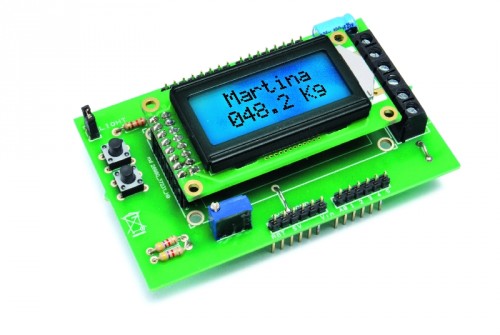
Wi-Fi Body Scale with Arduino

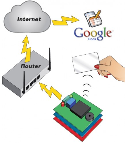
In this post we present the design of a scale that connects to the Internet and automatically sends weight info on a Google Document.

The project is composed of


Hardware

Taking a look at the diagram, we can distinguish three sections:

one for handling digital inputs (two buttons and scale’s switch),
the LCD manager
the analog signal acquisition from load cells


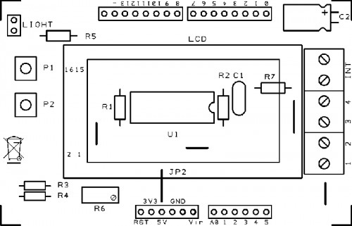
You may notice that P1 and P2 buttons are respectively managed by Arduino’s A3 and A4 inputs (configured as digital), while the INT switch reads the A5 signal (digital as well).

The LCD display used in our project belongs to the family of those based on HD44780 chipset, equipped with seven-pin control (RW, D4, D5, D6, D7, RS and Enable). As you can see from the diagram, RW is permanently connected to ground so it’s only operating in writing mode.

D4, D5, D6 and D7 pins are respectively managed by 3, 5, 6 and 7 digital pins of the Arduino Uno; RS is managed by pin 8 and the Enable pin from pin A0 (this configuration will also be specified in the software).

Besides the power supply (a VCC connected to 5V) and the ground (GND), the display requires a level of voltage between 0 and 5 volts to adjust the contrast in the input pin VO (adjustment made through R6 potentiometer).

Finally the display has 2 pin (A and K respectively anode and cathode) for switching on the backlight: feeding the pin with a voltage of 5V, the backlight is turned on, otherwise it is off.

The switching on and off is handled via a push-button switch that connects or disconnects the ground from the cathode.

Finally let’s analyze the part that manages the analog signal from the load cells: this is done by INA125 integrated component, a high precision amplifier developed specifically for measuring tools like scales.


The IC is fitted with two pins (6 and 7) representing the input of the differential amplification stage. These pins are connected to the two ends of the Wheatstone bridge (which in our project correspond to two of the load cell pins).

As you can figure out, the differential signal coming from the bridge has an absolute value of just a few millivolts: our project requires an amplification of about 500 times, obtained with a 120 ohm resistor.

The amplified output is provided at pins 10 and 11 of INA125; these pins are connected to A1 analog of the Arduino board, which therefore will be used for reading the value ADC.

R1: 39 ohm
R2: 1 kohm
R3: 4,7 kohm
R4: 4,7 kohm
R5: 330 ohm
R6: Trimmer 10 kohm
R7: 4,7 kohm

C1: 100 nF 63 VL
C2: 100 µF 25 VL

U1: INA125

P1: Microswitch
P2: Microswitch

LCD: Display LCD 8×2


Hacking  the Velleman scale

Our system is designed to be matched to the high-capacity scale produced by Velleman. But you can using any scale usign 4 load cells. The original Velleman electronics and display must be phased out and replaced with our project.

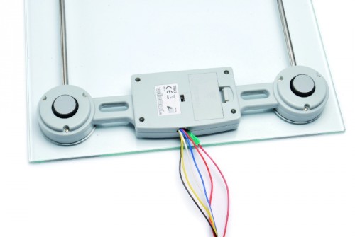
The scale structure is made up of 4 load cells (arranged on the 4 corners), which are configured between them so as to create a single Wheatstone bridge.

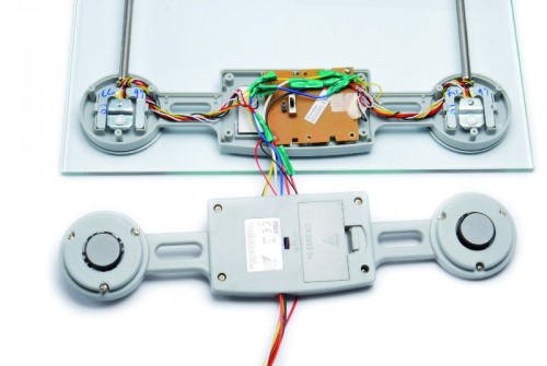
To make the connection to our board you must disassemble the lower section of the scale in order to access the electronics.

Referring to Fig A, which shows the structure of the scale viewed from below, with a quick visual analysis is easy to figure out that some blue and red wires are connected to each other while the yellow wires are connected to the switches positioned on the front of the two cells that identify the presence of a person.


To hack the scale follow these steps:


  • unsolder or cut all the red and blue wires, push in short those that were already shorted previously,

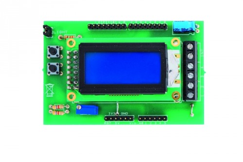
  • unsolder or cut the yellow wires coming from the cells numbered 1 and 3, put them in parallel (possibly by welding), extend them and take them to the two terminals on the new INT printed board (Fig.B)

  • unsolder or cut the white wire that is referred to as G3 (Wheatstone bridge mass) on the original printed circuit, extend take it to terminal 1 on the new printed circuit;

  • unsolder or cut the white wire that is referred to as G2 (Wheatstone bridge positive) on the original printed circuit, extend take it to terminal 3 on the new printed circuit;

  • unsolder or cut the white wire that is referred to as G1 and G4 on the original printed circuit, extend take it to terminal 4 and 2 on the new printed circuit (differential signal on the Wheatstone bridge)


The Sketch

As for the LCD, Arduino provides a convenient library (<LiquidCrystal.h>) already supporting different kinds of LCD (both 8 and 16 chars for 2 lines) based on the parallel interface chipset HD44780.

After the inclusion of the library, you must initialize the connection to the display, through LiquidCrystal LCDDisplay (8, A0, 3, 5, 6, 7), in this command, the parameters passed to the function and indicate Arduino’s hardware pins used to connect RS, Enable, D4, D5, D6 and D7 pins of the display.

Depending on the Arduino setup could be necessary to execute LCDDisplay.begin (width, height) in which the parameters indicate the physical dimensions of the display: LCDDisplay.begin (8, 2) in this case.

The library makes available instructions:

  • LCDDisplay.setCursor (x, y) to position the cursor in a certain position
  • LCDDisplay.print (String) to print strings


Management of Arduino’s EEPROM is done by the <EEPROM.h> library  that, once included, provides the functions:


  • EEPROM.write (add, date) to write a byte in a particular cell and

  • EEPROM.read (add) that the instead reads a byte from one cell (the add parameter specifies the address of the EEPROM cell).


Wi-Fi network and internet connection are managed thanks to the <WiServer.h> library; you just need to define some variables to configure the network (like IP’s and Network masks).


The adapter to connect and publish data on Google Documents shall operate as a Web Client: this configuration is done in the setup instruction WiServer.init (NULL) in which the NULL parameter specifies client mode.


You must create a function that will receive and handle the response from the server, this is done by the googlePublish.setReturnFunc  (Gestione_Risposte_Web) instruction  in our example. This function must be defined later in the code: in our example is void Gestione_Risposte_Web (char * data, int len) and receives as parameters both a pointer to a string containing the response and the length (in bytes) of the response.


Sending information requires to make a POST request to Google’s servers: WiServer library makes available a POSTrequest just to do this.


You must define the IP address of the server to which you want to connect (Google in our case) and define a structure of the POSTrequest (in our case, the variable is called googlePublish) containing the IP address of the server, the TCP / IP port the server name (spreadsheets.google.com), URL of POST execution and finally a function (SearchQuery in our case) that builds POST request body.


/******************************************************
 BilanciaWiFi
 Autori: Ingg. Tommaso Giusto e Ing. Alessandro Giusto
 Email:  tommro@libero.it
******************************************************/

// Inclusione Libreria per Display LCD 8x2
#include <LiquidCrystal.h>
// Inclusione Libreria per EEPROM scheda
#include <EEPROM.h>
// Inclusione Libreria per Server Web WiFi
#include <WiServer.h>
// Inclusione Libreria per SD Card
//#include <SD.h>

// Definizione pin INPUT/OUTPUT
const int PinVPeso = A1;         // Ingresso analogico uscita peso
const int PinPulsanteP1 = A3;    // Ingresso pulsante P1 su A3
const int PinPulsanteP2 = A4;    // Ingresso pulsante P2 su A4
const int PinInterruttore = A5;  // Ingresso interruttore su A5

// Definizione/Inizializzazione PIN Display LCD
// LCD RS pin D8
// LCD Enable on pin A0
// LCD D4, D5, D6, D7 on pins D3, D5, D6, D7
// LCD R/W pin a massa
// LCD V0 pin trimmer tra +5V e massa
LiquidCrystal LCDDisplay (8, A0, 3, 5, 6, 7);

/******************************************************
 Definizione struttura EEPROM
******************************************************/

/*****************************************************/
// Byte 0x000        Nome
// ...               Utente
// Byte 0x01F        000 (0x00 Carattere fine stringa)
// ...               
// ...               
// ...               
// Byte 0x120        Nome
// ...               Utente
// Byte 0x13F        009 (0x00 Carattere fine stringa)
/*****************************************************/
#define StartNomiUtentiEEPROMADD          0x0000
#define EndNomiUtentiEEPROMADD            0x013F
#define DimensioneNomeUtenteEEPROMADD     32
#define NumMaxNomiUtenti                  10

/*****************************************************/
// Byte 0x140        Parte Alta Peso Utente 000
// Byte 0x141        Parte Bassa Peso Utente 000
// ...               
// ...               
// ...               
// Byte 0x152        Parte Alta Peso Utente 009
// Byte 0x153        Parte Bassa Peso Utente 009
/*****************************************************/
#define StartPesiUtentiEEPROMADD          0x0140
#define EndPesiUtentiEEPROMADD            0x0153
#define DimensionePesoUtenteEEPROMADD     2

#define PesoMIN                           100
#define PesoMAX                           2000
#define AnalogDifferenzaPesoMAX           15

#define CalibrazioneSensoreMIN            0
#define CalibrazioneSensoreMAX            80

/******************************************************
 Definizione variabili globali
******************************************************/

// Definizione Parametri Rete Wireless
#define WIRELESS_MODE_INFRA	1  // Infrastrutturata (basata su Access Point)
#define WIRELESS_MODE_ADHOC	2  // Ad-hoc (senza Access Point)

// Parametri di rete
unsigned char local_ip[] = {192, 168, 0, 89};      // Indirizzo IP
unsigned char gateway_ip[] = {192, 168, 0, 254};	    // Indirizzo gateway IP
unsigned char subnet_mask[] = {255, 255, 255, 0};   // Subnet Mask
const prog_char ssid[] PROGMEM = {"FlashMob"};	    // SSID access point

// Selezione tipo di cifratura rete Wireless
unsigned char security_type = 0;  // 0 -> nessuna cifratura
                                  // 1 -> cifratura WEP
                                  // 2 -> cifratura WPA
                                  // 3 -> cifratura WPA2

// Password cifratura per WPA/WPA2 (max. 64 cratteri)
const prog_char security_passphrase[] PROGMEM = {"12345678"};

// Password cifratura per WEP 128-bit keys
prog_uchar wep_keys[] PROGMEM = {0x01, 0x02, 0x03, 0x04, 0x05, 0x06, 0x07, 0x08, 0x00, 0x00, 0x00, 0x00, 0x00,
				 0x00, 0x00, 0x00, 0x00, 0x00, 0x00, 0x00, 0x00, 0x00, 0x00, 0x00, 0x00, 0x00,
				 0x00, 0x00, 0x00, 0x00, 0x00, 0x00, 0x00, 0x00, 0x00, 0x00, 0x00, 0x00, 0x00,
				 0x00, 0x00, 0x00, 0x00, 0x00, 0x00, 0x00, 0x00, 0x00, 0x00, 0x00, 0x00, 0x00};

// Selezione tipo di rete Wireless infrastrutturata
unsigned char wireless_mode = WIRELESS_MODE_INFRA;

// Variabili per lunghezza SSID e password di cifratura
unsigned char ssid_len;
unsigned char security_passphrase_len;

// Definizione Parametri Pubblicazione Google
// Indirizzo IP per server www.google.it
uint8 google_ip[] = {209, 85, 229, 101};

// Richiesta POST verso GOOGLE
POSTrequest googlePublish (google_ip, 80, "spreadsheets.google.com", "", searchQuery);

// Stringa per eseguire pubblicazione
char newURL[] = {"/formResponse?formkey=dDFPcWhxNlZxMEpnUnhNdE5fT1lDcWc6MQ&ifq&entry.0.single=++++++++++++++++++++++++++++++++&entry.1.single=999,9&submit=Submit"};

// This function generates the body of our POST request
void searchQuery() {
}

// Indica presenza SD Card
//boolean presenzaSDCard;

// Inizializzazione Scheda
void setup() {
  // Inizializzo dimensioni LCD (8x2)
  LCDDisplay.begin (8, 2);

  // Inizializzo pin usati come INPUT/OUTPUT
  pinMode (PinInterruttore, INPUT);  
  pinMode (PinPulsanteP1, INPUT);
  pinMode (PinPulsanteP2, INPUT);

  // Se all'accensione rilevati tutti e 2 i pulsanti premuti
  if ((PulsantePremuto (PinPulsanteP1) == 1) &&
      (PulsantePremuto (PinPulsanteP2) == 1)) {
    // Segnalo inizializzazione in corso
    LCDDisplay.setCursor (0, 0);
    LCDDisplay.print ("Init EEP");
    LCDDisplay.setCursor (0, 1);
    LCDDisplay.print ("in corso");

    // Inizializzo EEPROM scheda
    InizializzaEEPROM();
    // Attesa
    delay (500);
  }
  // Inizializzo porta seriale
  Serial.begin (9600);  
  Serial.println ("Bilancia WiFi");
  Serial.println ("By Ingg. Tommaso e Alessandro Giusto");
  // Invio stato utenti
  InviaProgrammazioneUtenti();

  // Segnalo Avvio Web
  LCDDisplay.setCursor (0, 0);
  LCDDisplay.print ("  Init  ");
  LCDDisplay.setCursor (0, 1);
  LCDDisplay.print ("  web   ");  

  // Inizializzo WiServer
  WiServer.init (NULL);
  WiServer.enableVerboseMode (false);

  // Inizializzazione richiesta POST (parametro indica funzione a cui verra' passata la risposta)
  googlePublish.setReturnFunc (Gestione_Risposte_Web);    

/*
  // Inizializzo SD Card
  pinMode(10, OUTPUT);  
  presenzaSDCard = SD.begin (4);
  // Se inizializzazione SD fallita  
  if (presenzaSDCard == false)
    Serial.println ("Init SD FAULT!");
  // Se inizializzazione SD riuscita
  else
    Serial.println ("Init SD OK!");
*/
}

// Programma Principale
void loop() {
  // Ciclo infinito di esecuzione
  for (;;) {
    // Gestione Peso
    GestionePeso();

    // Per circa 1 sec
    for (byte tmp = 0; tmp < 250; tmp++) {
      // Gestione programmazione seriale
      GestioneSeriale();
      // Gestione WiServer
      GestioneWiServer();
      // Attesa
      delay (4);
    }    // Chiusura ciclo for per circa 1 sec
  }    // Chiusura ciclo infinito di esecuzione
}

/******************************************************
 Definizione funzioni
******************************************************/

// Funzione Gestione Peso
void GestionePeso() {
  // Indice utente selezionato
  //    0,..,(NumMaxNomiUtenti-1) -> selezionato utente 1,..,NumMaxNomiUtenti
  //    0xFF -> nessun utente selezionato
  static int IndiceUtenteSelezionato = 0xFF;
  // Indica l'indice carattere visualizzato  
  static int IndiceCarattere = 0;
  String NomeUtenteSelezionato;
  int PesoUtenteSelezionato;
  int LunghezzaNomeUtenteSelezionato;
  int ValoreSensorePeso1, ValoreSensorePeso2;
  int ValoreSensorePesoTMP1, ValoreSensorePesoTMP2, ValoreSensorePesoTMP3, ValoreSensorePesoTMP4;
  static int CalibrazioneSensore;
  int CalibrazioneSensoreTMP;
  int PesoCalcolato;
  int tmp;

  // Se non premuto interruttore (utente non salito)
  if (PulsantePremuto (PinInterruttore) == 0) {
    // Leggo valore sensore per calibrazione
    CalibrazioneSensoreTMP = analogRead (PinVPeso);
    // Se valore sensore per calibrazione valido
    if ((CalibrazioneSensoreTMP >= (int) (CalibrazioneSensoreMIN)) &&
      (CalibrazioneSensoreTMP <= (int) (CalibrazioneSensoreMAX)))
      // Aggiorno valore sensore per calibrazione
      CalibrazioneSensore = CalibrazioneSensoreTMP;
  }    // Chiusura if non premuto interruttore (utente non salito)

  // Se premuto tasto 1
  if (PulsantePremuto (PinPulsanteP1) == 1) {
    // Azzero indice carattere visualizzato
    IndiceCarattere = 0;

    // Verifico tutte le posizioni utente
    for (tmp = 0; tmp < NumMaxNomiUtenti; tmp++) {
      // Seleziono utente selezionato
      switch (IndiceUtenteSelezionato) {
        // Se selezionato ultimo utente/nessun utente selezionato
        case (NumMaxNomiUtenti - 1): case 0xFF:
          // Seleziono primo utente
          IndiceUtenteSelezionato = 0;
          break;    // Chiusura case selezionato ultimo utente/nessun utente selezionato

        // Se selezionato altro utente
        default:
          // Seleziono prossimo utente
          IndiceUtenteSelezionato++;
          break;    // Chiusura case nessun utente selezionato
      }    // Chiusura switch seleziono utente selezionato

      // Se trovato utente con nome non nullo
      if (LeggiNomeUtente (IndiceUtenteSelezionato).length() != 0x00)
        // Blocco ciclo for verifico tutte le posizioni utente
        break;
    }    // Chiusura ciclo for verifico tutte le posizioni utente

    // Se non trovato utente con nome non nullo
    if (tmp == NumMaxNomiUtenti)
      // Seleziono nessun utente
      IndiceUtenteSelezionato = 0xFF;
  }    // Chiusura if premuto tasto 1

  // Se utente selezionato
  if (IndiceUtenteSelezionato != 0xFF) {
    // Leggo nome/peso utente
    NomeUtenteSelezionato = LeggiNomeUtente (IndiceUtenteSelezionato);
    PesoUtenteSelezionato = LeggiPesoUtente (IndiceUtenteSelezionato);
    // Calcolo lunghezza nome utente    
    LunghezzaNomeUtenteSelezionato = NomeUtenteSelezionato.length();
    // Seleziono lunghezza nome utente
    switch (LunghezzaNomeUtenteSelezionato) {
      case 0:
        // Indico nessun utente selezionato
        IndiceUtenteSelezionato = 0xFF;
        break;
      case 1: case 2: case 3: case 4: case 5: case 6: case 7:
        LCDDisplay.clear();
        LCDDisplay.setCursor ((8 - LunghezzaNomeUtenteSelezionato) / 2, 0);
        LCDDisplay.print (NomeUtenteSelezionato);
        break;
      case 8:
        LCDDisplay.setCursor (0, 0);
        LCDDisplay.print (NomeUtenteSelezionato);
        break;
      default:
        if ((IndiceCarattere + 8) > LunghezzaNomeUtenteSelezionato)
          IndiceCarattere = 0;

        LCDDisplay.setCursor (0, 0);
        LCDDisplay.print (&NomeUtenteSelezionato[IndiceCarattere]);

        // Messaggio scorrevole
        IndiceCarattere++;
        if ((IndiceCarattere + 8) > LunghezzaNomeUtenteSelezionato)
          IndiceCarattere = 0;
        break;
    }    // Chiusura switch seleziono lunghezza nome utente
    LCDDisplay.setCursor (0, 1);
    LCDDisplay.print (PesoUtenteSelezionato / 1000);
    LCDDisplay.print ((PesoUtenteSelezionato % 1000) / 100);
    LCDDisplay.print ((PesoUtenteSelezionato % 100) / 10);
    LCDDisplay.print (".");
    LCDDisplay.print (PesoUtenteSelezionato % 10);    
    LCDDisplay.print (" Kg");

    // Se premuto interruttore (utente salito)
    if (PulsantePremuto (PinInterruttore) == 1) {
      LCDDisplay.setCursor (0, 1);
      LCDDisplay.print ("..... Kg");

      // Leggo valore analogico peso
      for (;;) {
        // Attesa
        delay (500);
        // Eseguo prima lettura peso
        ValoreSensorePesoTMP1 = analogRead (PinVPeso);
        delay (125);
        ValoreSensorePesoTMP2 = analogRead (PinVPeso);
        delay (125);
        ValoreSensorePesoTMP3 = analogRead (PinVPeso);
        delay (125);
        ValoreSensorePesoTMP4 = analogRead (PinVPeso);
        delay (125);
        ValoreSensorePeso1 = ((ValoreSensorePesoTMP1 + ValoreSensorePesoTMP2 + ValoreSensorePesoTMP3 + ValoreSensorePesoTMP4) / 4);

        // Attesa
        delay (500);
        // Eseguo seconda lettura peso
        ValoreSensorePesoTMP1 = analogRead (PinVPeso);
        delay (125);
        ValoreSensorePesoTMP2 = analogRead (PinVPeso);
        delay (125);
        ValoreSensorePesoTMP3 = analogRead (PinVPeso);
        delay (125);
        ValoreSensorePesoTMP4 = analogRead (PinVPeso);
        delay (125);
        ValoreSensorePeso2 = ((ValoreSensorePesoTMP1 + ValoreSensorePesoTMP2 + ValoreSensorePesoTMP3 + ValoreSensorePesoTMP4) / 4);

        // Se peso stabilizzato
        if ((ValoreSensorePeso1 <= ValoreSensorePeso2) && ((ValoreSensorePeso2 - ValoreSensorePeso1) < (int) (AnalogDifferenzaPesoMAX)) ||
            (ValoreSensorePeso1 > ValoreSensorePeso2) && ((ValoreSensorePeso1 - ValoreSensorePeso2) < (int) (AnalogDifferenzaPesoMAX)))
          // Blocco ciclo for leggo valore analogico peso
          break;
      }    // Chiusura ciclo for leggo valore analogico peso

      // Calcolo peso utente
      PesoCalcolato = (int) (ValoreSensorePeso2 - CalibrazioneSensore);
      PesoCalcolato = (PesoCalcolato + (((int) (PesoCalcolato * (int) (10))) / (int) (62)));

//    68.1 KG
//    642   con calibrazione: 62 -> Veff = 580

      // Se peso valido
      if ((PesoCalcolato >= (int) (PesoMIN)) && (PesoCalcolato <= (int) (PesoMAX))) {
        // Memorizzo peso utente
        ScriviPesoUtente (IndiceUtenteSelezionato, PesoCalcolato);

        // Visualizzo peso calcolato
        LCDDisplay.setCursor (0, 1);
        LCDDisplay.print (PesoCalcolato / 1000);
        LCDDisplay.print ((PesoCalcolato % 1000) / 100);
        LCDDisplay.print ((PesoCalcolato % 100) / 10);
        LCDDisplay.print (".");
        LCDDisplay.print (PesoCalcolato % 10);    
        LCDDisplay.print (" Kg");

        // Richiedo pubblicazione        
        LCDDisplay.setCursor (0, 0);
        LCDDisplay.print ("Pubblic?");

        // Per massimo 5 secondi attendo pressione tasto 2
        for (tmp = 0; tmp < 10; tmp++) {
          // Se premuto tasto 2
          if (PulsantePremuto (PinPulsanteP2) == 1) {
            // Indico pubblicazione in corso     
            LCDDisplay.setCursor (0, 0);
            LCDDisplay.print ("Pubblic.");
            LCDDisplay.setCursor (0, 1);
            LCDDisplay.print ("  wait  ");

            // Eseguo pubblicazione
            for (tmp = 0; tmp < NomeUtenteSelezionato.length(); tmp++) {
              newURL[76 + tmp] = NomeUtenteSelezionato.charAt(tmp);
              if (newURL[76 + tmp] == ' ')
                newURL[76 + tmp] = '+';
            }
            newURL[124] = ((PesoCalcolato / 1000) + 0x30);
            newURL[125] = (((PesoCalcolato % 1000) / 100) + 0x30);      
            newURL[126] = (((PesoCalcolato % 100) / 10) + 0x30);      
            newURL[128] = ((PesoCalcolato % 10) + 0x30);      
            googlePublish.setURL(newURL);
            googlePublish.submit();    
            delay (500);
            // Blocco ciclo for
            break;
          }
          delay (500);          
        }    // Chiusura ciclo for per massimo 5 secondi attendo pressione tasto 2
/*
        // Se SD rilevata
        if (presenzaSDCard == true) {
          // Verifico/Creo directory BilanciaWiFi
          if (!(SD.exists ("BilanciaWiFi")))
            SD.mkdir ("BilanciaWiFi");

          // Memorizzo il peso su file
          File filePeso;
          // Apro il file in scrittura
          char nomeFilePeso[50] = {"BilanciaWiFi/"};
          for (tmp = 0; tmp < NomeUtenteSelezionato.length(); tmp++) {
            charTmp[0] = NomeUtenteSelezionato.charAt(tmp);
            strcat (nomeFilePeso, charTmp);
          }
          strcat (nomeFilePeso, ".txt");          
          filePeso = SD.open (nomeFilePeso, FILE_WRITE);

          // Se apertura file OK
          if (filePeso) {
            // Memorizzo il peso
            filePeso.print ((PesoCalcolato / 1000) + 0x30);
            filePeso.print (((PesoCalcolato % 1000) / 100) + 0x30);
            filePeso.print (((PesoCalcolato % 100) / 10) + 0x30);
            filePeso.print (".");
            filePeso.print ((PesoCalcolato % 10) + 0x30);
            filePeso.print (" Kg");
            // Chiudo il file:
            filePeso.close();
          }
        }
*/

        LCDDisplay.setCursor (0, 0);
        LCDDisplay.print ("  Step  ");
        LCDDisplay.setCursor (0, 1);
        LCDDisplay.print ("  off   ");

        // Attendo utente scende dalla bilancia
        for (;;) {
          // Se non premuto interruttore (utente non salito)
          if (PulsantePremuto (PinInterruttore) == 0)
            break;
        }
      }    // Chiusura if peso valido
    }    // Chiusura if premuto interruttore (utente salito)
  }    // Chiusura if utente selezionato

  // Se nessun utente selezionato
  else {
    LCDDisplay.setCursor (0, 0);
    LCDDisplay.print (" Chose  ");
    LCDDisplay.setCursor (0, 1);
    LCDDisplay.print (" user   ");
  }    // Chiusura if nessun utente selezionato
}

// Funzione Gestione Seriale
void GestioneSeriale() {
  String comandoRicevutoString = "";
  int numeroUtenteRicevuto;
  String nomeUtenteRicevuto = "";

  // Se ricevuti dati dalla porta seriale
  if (Serial.available()) {
    // Attendo tutti i dati
    delay (250);

    // Ricevo i dati
    while (Serial.available())
      comandoRicevutoString += (char) (Serial.read());

    // Invio comando ricevuto    
    Serial.println (comandoRicevutoString);

    // Se ricevuti almeno 15 caratteri
    if (comandoRicevutoString.length() >= 15) {
      // Se ricevuto comando programmazione nome utente (NOME_UTENTE_xx=)USER_NAME_01=Boris
      if ((comandoRicevutoString.substring (0, 12).equals("P_USER_NAME_")) &&
          (isdigit(comandoRicevutoString.charAt (12))) &&
          (isdigit(comandoRicevutoString.charAt (13)))) {
        // Estraggo numero utente ricevuto
        numeroUtenteRicevuto = (((comandoRicevutoString.charAt (12) - 0x30) * 10) +
                                (comandoRicevutoString.charAt (13) - 0x30));
        // Se ricevuto numero utente corretto
        if ((numeroUtenteRicevuto >= 1) && (numeroUtenteRicevuto <= NumMaxNomiUtenti)) {
          // Estraggo nome utente
          nomeUtenteRicevuto = comandoRicevutoString.substring (15);
          // Se nome troppo lungo
          if (nomeUtenteRicevuto.length() > DimensioneNomeUtenteEEPROMADD)
            // Tronco il nome
            nomeUtenteRicevuto = nomeUtenteRicevuto.substring (0, DimensioneNomeUtenteEEPROMADD);

          // Memorizzo il nome
          ScriviNomeUtente (numeroUtenteRicevuto - 1, nomeUtenteRicevuto);
          // Azzero il relativo peso
          AzzeraPesoUtente (numeroUtenteRicevuto - 1);
          // Indico OK
          Serial.println ("OK");
          // Invio su  porta seriale lo stato utenti
          InviaProgrammazioneUtenti();
          // Termino funzione
          return;
        }
      }
    }  

    // Indico errore
    Serial.println ("FAULT");
    // Termino funzione
    return;
  }
}

// Invia su  porta seriale lo stato utenti
void InviaProgrammazioneUtenti() {
  for (int numeroUtente = 0; numeroUtente < NumMaxNomiUtenti; numeroUtente++) {
    Serial.print ("Us. ");
    Serial.print ((numeroUtente + 1) / 10);
    Serial.print ((numeroUtente + 1) % 10);
    Serial.print (": ");
    Serial.println (LeggiNomeUtente (numeroUtente));
  }
}

// Funzione Gestione WiServer
void GestioneWiServer() {
  // Gestione WiServer
  WiServer.server_task();
}

// Gestione diverse risposte provenienti dal WEB
void Gestione_Risposte_Web (char* data, int len) {

  // Print the data returned by the server
  // Note that the data is not null-terminated, may be broken up into smaller packets, and 
  // includes the HTTP header. 
  while (len-- > 0) {
    Serial.print(*(data++));
  } 

}

// Scrive il nome di un utente
// INPUT:   Posizione utente (0,..,9)
//          Nome utente in formato stringa
// OUTPUT:  -
// Note:    -
void ScriviNomeUtente (int NomePosition, String NomeUtente) {
  // Azzero nome utente selezionato
  AzzeraNomeUtente (NomePosition);

  // Scrivo i caratteri nome utente selezionato
  for (int tmp = 0; tmp < NomeUtente.length(); tmp++)
    EEPROM.write (StartNomiUtentiEEPROMADD + tmp +
                  (NomePosition * DimensioneNomeUtenteEEPROMADD), NomeUtente.charAt(tmp));
}

// Legge il nome di un utente
// INPUT:   Posizione utente (0,..,9)
// OUTPUT:  Nome utente in formato stringa
// Note:    -
String LeggiNomeUtente (int NomePosition) {
  String NomeUtente = "";
  char NomeUtenteChar;

  // Leggo i caratteri nome utente selezionato
  for (int tmp = 0; tmp < DimensioneNomeUtenteEEPROMADD; tmp++) {
    // Leggo singolo carattere
    NomeUtenteChar = EEPROM.read (StartNomiUtentiEEPROMADD + tmp +
                                  (NomePosition * DimensioneNomeUtenteEEPROMADD));

    // Se trovato carattere fine nome
    if (NomeUtenteChar == 0x00)
      // Blocco ciclo for leggo i caratteri nome utente selezionato
      break;

    // Accodo carattere letto
    NomeUtente = NomeUtente + NomeUtenteChar;
  }

  // Ritorno il nome
  return (NomeUtente);
}

// Azzera il nome di un utente
// INPUT:   Posizione utente (0,..,9)
// OUTPUT:  -
// Note:    -
void AzzeraNomeUtente (int NomePosition) {
  // Azzero caratteri nome utente selezionato
  for (int tmp = 0; tmp < DimensioneNomeUtenteEEPROMADD; tmp++)
    EEPROM.write (StartNomiUtentiEEPROMADD + tmp +
                  (NomePosition * DimensioneNomeUtenteEEPROMADD), 0); 
}

// Scrive il peso di un utente
// INPUT:   Posizione utente (0,..,9)
//          Peso utente
// OUTPUT:  -
// Note:    -
void ScriviPesoUtente (int PesoPosition, int PesoUtente) {
  // Memorizzo peso nome utente
  EEPROM.write (StartPesiUtentiEEPROMADD + 
                (PesoPosition * DimensionePesoUtenteEEPROMADD), (byte) (PesoUtente >> 8));
  EEPROM.write (StartPesiUtentiEEPROMADD + 1 +
                (PesoPosition * DimensionePesoUtenteEEPROMADD), (byte) (PesoUtente & 0x00FF));
}

// Legge il peso di un utente
// INPUT:   Posizione utente (0,..,9)
// OUTPUT:  Peso utente
// Note:    -
int LeggiPesoUtente (int PesoPosition) {
  // Ritorno il peso
  return (((int) (EEPROM.read (StartPesiUtentiEEPROMADD +
                               (PesoPosition * DimensionePesoUtenteEEPROMADD))) << 8) +
           (int) (EEPROM.read (StartPesiUtentiEEPROMADD + 1 +
                               (PesoPosition * DimensionePesoUtenteEEPROMADD))));
}

// Azzera il peso di un utente
// INPUT:   Posizione utente (0,..,9)
// OUTPUT:  -
// Note:    -
void AzzeraPesoUtente (int PesoPosition) {
  // Azzero peso nome utente
  ScriviPesoUtente (PesoPosition, 0);
}

// Inizializza EEPROM scheda
// INPUT:   -
// OUTPUT:  -
// Note:    -
void InizializzaEEPROM() {
  // Azzero i nomi/pesi di tutti gli utenti
  for (int tmp = 0; tmp < NumMaxNomiUtenti; tmp++) {
    AzzeraNomeUtente (tmp);
    AzzeraPesoUtente (tmp);
  }    
}

// Verifica lo stato di un pulsante
// INPUT:   Pin pulsante
// OUTPUT:  Stato pulsante    0 -> pulsante non premuto
//                            1 -> pulsante premuto
// Note:    -
int PulsantePremuto (int PinPulsante) {
  if (digitalRead (PinPulsante) == LOW)
    return (1);
  else
    return (0);
}


Install the WiShield libraries


To work properly, the Wifi shield requires specific libraries that must be installed in the Arduino IDE used to compile the sources so you’ll need to put these libraries in the Arduino libraries path.


The library supports multiple operating modes (APP_WEBSERVER, APP_WEBCLIENT, APP_SOCKAPP, APP_UDPAPP and APP_WISERVER).

The default value is APP_WEBSERVER, which runs on most Arduino systems but has several limitations. The main limitation is that it can’t function both as a client and server simultaneously.


It is therefore recommended the APP_WISERVER (in the library named “WiServer.h“) which allows the Arduino shield equipped with Wi-Fi to be configured and operated either as a Web Server as a Web Client.


In the first case, you can serve connection requests from external web clients and send HTML pages in response, in the second it will be possible to connect to a web server and send GET or POST requests.


To configure the WiShield library as APP_WISERVER you must open the apps-conf.h file, comment the “#define“ APP_WEBSERVER row and uncomment the “#define” of APP_WISERVER row.


Something like:


/ / # define APP_WEBSERVER

/ / # define APP_WEBCLIENT

/ / # define APP_SOCKAPP

/ / # define APP_UDPAPP

# defineAPP_WISERVER


Configuring publishing

Performing data publication on Google Documents requires three distinct steps:


  1. Configuring Wi-Fi network access;
  2. Creating a Google Docs form module: each module is characterized by an identifying 34 characters string – FormKey) and each field is characterized by an identification number (called Entry).
  3. Inserting the FormKey / Entry in the Arduino software.


Configuring network parameters

First you must configure and update the IP address, Subnet Mask, Gateway IP and Network SSID, then select the encryption mode and change password information for your network. Save all, compile and run the upload Software tab.

Creating the Google  module doc

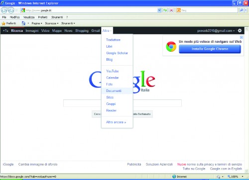
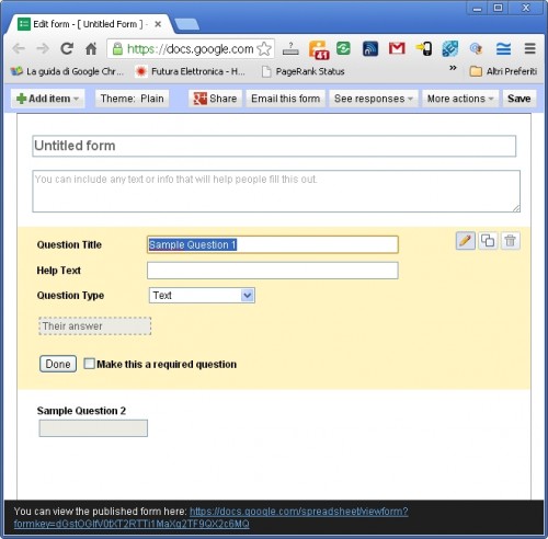
Create a form on Google Docs, modify the form with two fields (username and weight, both of type string) and save the job. (the result is something like the one shown in Figure). In our case, we left the default file name and called the two fields “User Name” and “User weight”

take note of this key string because then it will be inserted in the Arduino software: as you can see from the picture, the link shows the form key assigned to the module (in this example, the link is: https://docs.google.com/spreadsheet/viewform?formkey=dDFPcWhxNlZxMEpnUnhNdE5fT1lDcWc6MQ which implies that the form assigned key is “dDFPcWhxNlZxMEpnUnhNdE5fT1lDcWc6MQ”);


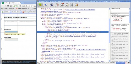
Clicking on the link will open a new page that shows the data entry form: within this form text fields are marked with “entry.0.single“, “entry.1.single“, etc … (basically with an integer id)

 To see which number has been assigned to our fields you need to display the HTML source of the form (the result is something like the one shown in this Figure).

You can easily find the ID numbers assigned to different fields (in our example “entry.0.single” is the “Name” and “entry.1.single” is the “weight“).

Take note of this information because it will be included in the source Arduino as well.

Formkey / entry

Once you have created the form, the Arduino source will be configured so that it is compatible with the form you created.

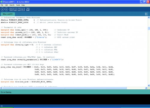
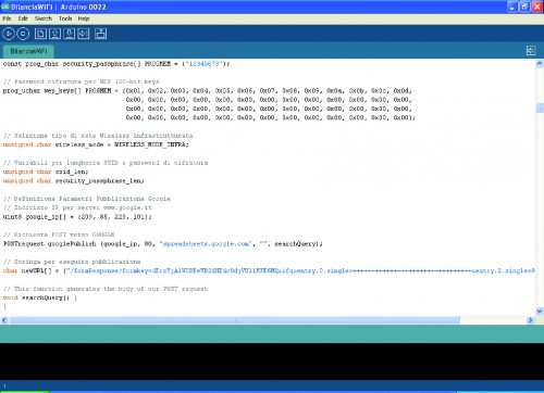
A variable is defined in Arduino source named newURL[]: the variable is initialized with a standard format then modified to perform publication (refer to Figure 11 to identify it in the code).


Replace the default values with those obtained at the time of the creation of the form, compile and download it to the Arduino board.


How to program user names

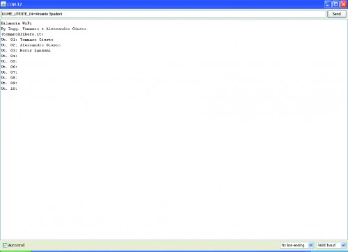
The configuration of user names can be made via serial port and Serial Monitor. To program it, connect to the board (via USB cable) and open the Arduino Serial Monitor. As a first step the card sends a summary of the current configuration.


To program a new user name you must send a string in the format “P_USER_NAME_xx = User Name” with xx between 01 and 10 ID (put an empty string to delete the selected user.) If all the posted information is correct, this is confirmed by the message “Ok” otherwise “Fault”.


Using the scale


The scale software is able to distinguish up to 10 users (each identified by its name) and, for each one, it stores the last measured weight.


If you want to clear the memory (which we recommend at first use) is sufficient to hold down either of the two buttons (the display indicates the operation with “EEP init in progress”).

Later, you can configure names following the procedure described in the “Programming user names” section.


As the next step the Web management interface will start and the system will enter its normal operation. The user selection is done by pressing button P1.


Going over the scale starts the weighing procedure (lasting several seconds): weight is displayed and stored and the scale asks for publishing on the web: by pressing P2 the operation is performed.

Using Arduino shields with the Raspi

With hundreds of Arduino shields available for any imaginable application, it’s a shame they can’t be used with the Raspberry Pi. Breaking out the Raspi GPIO pins to Arduino-compatible headers would allow makers and tinkerers to reuse their shields with a far more capable computing platform.

The folks over at Cooking Hacks realized a Raspi to Arduino shield bridge would be an awesome device, so they made their own, complete with a software library that allows you to port your Arduino code directly to the Raspberry Pi.

There are a few limitations with the Raspberry Pi’s GPIO headers; the Raspi doesn’t have analog inputs, so the Cooking Hacks team added an 8-channel digital to analog converter. Along with analog inputs and the headers required to pop a shield on the board, there’s also a socket for an XBee module.

The software library contains most of the general Arduino functions such as digitalWrite() and digitalRead(). There Serial, Wire, and SPI libraries are also implemented, allowing any device that communicates through UART, I2C, or SPI to talk directly to the Raspberry Pi.

While the Raspi Arduino bridge doesn’t allow for PWM in the same capacity as an Arduino, you’re always welcome to whip up a servo or LED shield for this neat little adapter.


Filed under: arduino hacks, Raspberry Pi

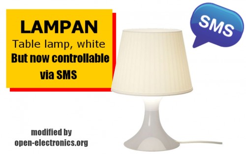
IKEA SMS lamp with GSM shield

-->-->-->-->


We create a lamp controlled by SMS using a GSM shield, a RGB shield and a Arduino UNO.
Due to the simplicity of these boards, simply plug one over the other and connect a strip led to have a lighting effect.
Then sending normal text messages from any phone, you can turn on and choose the color to set.

The scketch check the text of the received message, if the SMS contains a character, it follows on the corresponding color.
It ‘also provided a fader functions can be called with the character F

This is the list commands:
R to set RED
G to set GREEN
B to set BLUE
Y to set YELLOW
O to set ORANGE
P to set PURPLE
W to set WHITE
F to set the fader function

This is just an example of the possible applications of the GSM / GPRS shield.
You can for example control the home lighting with a simple text message, or receive an SMS in case of alarm.
In addition, the SIM900 has the capacity to also decode DTMF tones, so you can call this in the sim GSM shield and switch loads directly from the telephone keypad.

The complete library it contains many other functions through which you can make calls, connect to the Internet, send and receive SMS.

This is the simple firmware in Arduino.


//GSM Shield for Arduino
//www.open-electronics.org
//this code is based on the example of Arduino Labs

#include "SIM900.h"
#include "sms.h"
#include "SoftwareSerial.h"
#include "sms.h"
SMSGSM sms;
int red = 10;    // RED LED connected to PWM pin 3
int green = 5;    // GREEN LED connected to PWM pin 5
int blue = 6;    // BLUE LED connected to PWM pin 6
int r=50; int g=100; int b=150;
int rup; int gup; int bup;

boolean started=false;
char smsbuffer[160];
char n[20];
int fader=1;
int inc=10;

void setup() 
{
  //Serial connection.
  Serial.begin(9600);
  Serial.println("GSM Shield testing.");
  //Start configuration of shield with baudrate.
  if (gsm.begin(2400)){
    Serial.println("\nstatus=READY");
    started=true;  
  }
  else Serial.println("\nstatus=IDLE");
  if(started){
    delsms();
  }

};

void loop() 
{
  int pos=0;
  //Serial.println("Loop");
  if(started){
    pos=sms.IsSMSPresent(SMS_ALL);
    if(pos){
      Serial.println("IsSMSPresent at pos ");
      Serial.println(pos); 
      sms.GetSMS(pos,n,smsbuffer,100);
        Serial.println(n);
        Serial.println(smsbuffer);
        if(!strcmp(smsbuffer,"R")){
          Serial.println("RED");
          r=255;
          g=0;
          b=0;
        }      
        if(!strcmp(smsbuffer,"G")){
          Serial.println("GREEN");
          r=0;
          g=255;
          b=0;
        }    
        if(!strcmp(smsbuffer,"B")){
          Serial.println("BLUE");
          r=0;
          g=0;
          b=255;
        }  
        if(!strcmp(smsbuffer,"P")){
          Serial.println("PURPLE");
          r=255;
          g=0;
          b=255;
        }  
        if(!strcmp(smsbuffer,"Y")){
          Serial.println("YELLOW");
          r=255;
          g=255;
          b=0;
        }  
        if(!strcmp(smsbuffer,"O")){
          Serial.println("ORANGE");
          r=255;
          g=165;
          b=0;
        }  
        if(!strcmp(smsbuffer,"W")){
          Serial.println("WHITE");
          r=255;
          g=255;
          b=255;
        }  
        if(!strcmp(smsbuffer,"F")){
          Serial.println("FADER");
          fader=1;
          r=50; g=100; b=150;
        }
        else
        {
          fader=0;
        }  
        rgb(r, g, b);
        delsms();

    }
    if(fader){
      funcfader();
    }

  }
};

void delsms(){
  Serial.println("delsms");
  for (int i=0; i<10; i++){  //do it max 10 times
      int pos=sms.IsSMSPresent(SMS_ALL);
      if (pos!=0){
        Serial.print("\nFind SMS at the pos ");
        Serial.println(pos); 
        if (sms.DeleteSMS(pos)==1){    
          Serial.print("\nDeleted SMS at the pos ");
          Serial.println(pos);      
        }
        else
        {
          Serial.print("\nCant del SMS at the pos ");
          Serial.println(pos);         
        }
      }
    }

}

void funcfader(){
    if (rup==1){r+=1;}
    else{r-=1;}
    if (r>=255){rup=0;}
    if (r<=0){rup=1;}

    if (gup==1){g+=1;}
    else{g-=1;}
    if (g>=255){gup=0;}
    if (g<=0){gup=1;}

    if (bup==1){b+=1;}
    else{b-=1;}
    if (b>=255){bup=0;}
    if (b<=0){bup=1;}  
    rgb(r, g, b);
}

void rgb(int r, int g, int b)
{
  if (r>255) r=255;
  if (g>255) g=255;
  if (b>255) b=255;
  if (r<0) r=0;
  if (g<0) g=0;
  if (b<0) b=0;

  analogWrite(red, r); 
  analogWrite(green, g); 
  analogWrite(blue, b);   
}
-->-->-->-->-->-->
-->-->

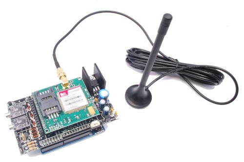
GSM GPS shield for Arduino

-->-->-->-->

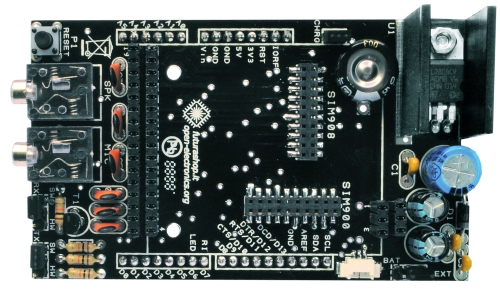
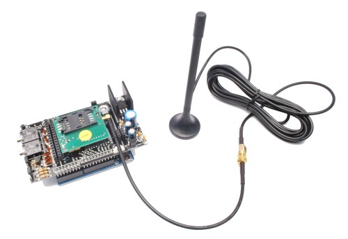
Shield for Arduino designed and based on the module GSM/GPRS SIM900 or the GSM/GPRS & GPS module SIM908, to make calls, voice and data connections via GPRS.


HARDWARE INNOVATIONS


This new version (old Arduino GSM shield) has several new hardware features, that allow maximum customization and provide many configurations.

We begin with the supply circuit a simple LM7805. To work, it is necessary to provide an input voltage between 7.5V and 12V. As shown in the circuit diagram, the input voltage, after being stabilized at 5 V, is reduced to 4.3 V by using a diode and provide power to modules that need a voltage between the 3.2 and 4.8 V. During the operations such as the use of GPRS, the module absorbs a current of about 1 A, therefore it is necessary that the power source is able to provide this current intensity.

An important technical feature is the serial adapter for the communication between the GSM module and Arduino. To reduce the tension has been used a simple voltage divider, while for raising the voltage from the GSM module to Arduino we chose a MOSFET BS170.

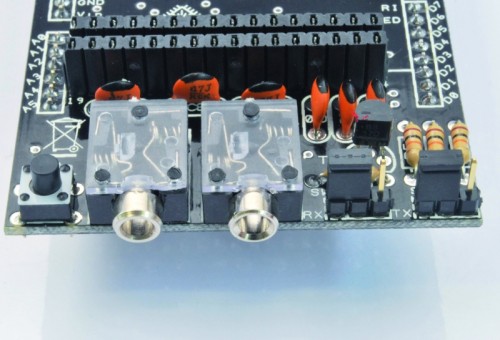
The news that is immediately evident is the presence of two jacks for audio. With a microphone and a headset with a 3.5 mm jack (just the standard headphones for computers), you can make a voice call

To preserve compatibility with the Arduino Mega, we changed the selection method for the serial communication. The two different serial communication modes (hardware or software) are selectable by jumper, leaving the user the choice between the two configurations ( for serial software in this new version we adopted pins 2 and 3) or possibly use the pin to your choice with a simple wire connection. With this solution you can use the Arduino Mega using two of the four serial that it has, or possibly carry out the communication through a serial software via two pins of your choice.

Always to preserve maximum flexibility and customization, there are some pins on the back of PCB, which allow to make the connections from the Arduino digital ports and the control signals data flow (CTS, RTS) or alerts for incoming calls or unread SMS (RI). In this new version, you can then disable these connections to save inputs or outputs pins.

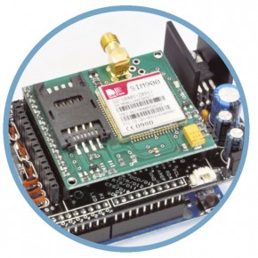
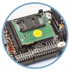
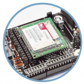
Comparing the new card with the previous one, you can see the presence of two connectors on the top.These additional connections allow the use of the shield also with the new small breakout for SIM900 and SIM908. The new module Simcom SIM908, is characterized by the presence of a GPS with 42 channels.

The scenery offered by this new module SIMCOM, in addition to GSM GPRS shield, it is quite remarkable: the creation of a GPS tracking device that can communicate the location via the Internet (or SMS) is now available to everyone, avoiding all the problems due to assembly and low-level programming.

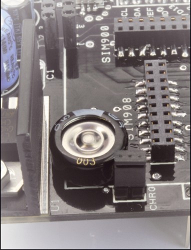
A further feature of this new version, concerns the presence of a supercap for circuit dedicated to the RTC (Real Time Clock). Inside the SIM900, as well as the SIM908, there is a circuit that is responsible for updating the clock even without power.


GSM GPS SHIELD SCHEMATICS


R1: 10 kohm
R2: 10 kohm
R3: 10 kohm
R4: 10 kohm

C1: 100 nF
C2: 470 µF 25 VL
C3: 100 nF
C4: 220 µF 16 VL
C5: 47 pF
C6: 47 pF
C7: 47 pF
C8: 47 pF
C9: 47 pF
C10: 47 pF
C11: 220 µF 16 VL
C12: 100 nF

CRCT:  0,1F

U1: 7805

T1: BS170

D1: 1N4007

P1: Microswitch

MIC: jack 3,5 mm
SPK: jack 3,5 mm


SOFTWARE INNOVATIONS

The software library related to the GSM GPRS shield has been updated.  The library is open-source and uses the hosting service Google Project, located at http://code.google.com/p/gsm-shield-arduino/ . The library is constantly updated and improved with the addition of new features, so please check that you always have the latest release.

The main enhancement is the TPC/IP communication support through GPRS.

With a simple function, you can connect Arduino to internet using the APN (Access Point Name) you choose. After that we will automatically get an IP address by the provider.

To establish communication you must define which device performs the function of the server (still waiting for some connection), such as that client (requires a connection to the server according to the information you want to achieve) and that leads to exchange data .

In the library there are two functions that allow us to set the device to listen on a particular port for connections (server), or to establish a connection based on the server address and port chosen (client) .

Once connected, you can send the data, which can be command strings or just the data you want to monitor, for this action there is a high-level function, which simplifies the management.


LIBRARY FUNCTIONS GSM GPRS

First, you must have the folder libraries, in the root directory of the Arduino, the folder GSM_GPRS containing all the functions you can use.

Now if you want to change the serial port, through the jumper, you have to modify the file GSM.cpp.

To save memory, we decided to divide the functions into different classes contained in different files, to allow you to include or not the code parts needed, thus going to save memory RAM, leaving it free for the rest of the program. For the basic operation is always necessary to include files SIM900.h and SoftwareSerial.h, while depending on the needs you may include call.h (for call handling), sms.h (for sending, receiving and saving SMS) and inetGSM.h (containing functions related to HTTP, and GPRS).

SIM900.h

You should always include this file. It contains the basic functions for starting and configuring the GSM module.  Simply call the functions using “GSM.” As a prefix.

int gsm.begin(int baudrate) Turn the power on and sets the baud rate for communication. gsm.TurnOn(9600);
void SimpleRead() Reads a byte from the serial buffer. gsm.SimpleRead();
void SimpleWrite(char* cmd) Writes the string (or an integer) on the serial port. gsm.SimpleRead(“AT+CSQ”);
char SendATCmdWaitResp (char const* AT_cmd_string, uint16_t start_comm_tmout, uint16_t max_interchar_tmout, char const* response_string,byte no_of_attempts) Sends an AT command passed as a parameter, controlling the time of timeout for the receipt of a response and between one character and another. After receiving the response, compares it with that expected, if different resends the command for the set number of times.The possible outputs are shown below, with the relative enumeration. AT_RESP_ERR_NO_RESP or -1: No response received.AT_RESP_ERR_DIF_RESP or 0: Response different from that expected.AT_RESP_OK or 1: The response contains the expected string. If (gsm.SendATCmdWaitResp (“AT”,500,50,”OK”,3)== AT_RESP_OK)
Serial.println(“OK”);


call.h

In case you want to make a call, or simply refuse to answer an incoming call, you must use this class. To use these functions simply instantiate the object in the sketch. The functions listed in the table below refers to an object created with the following command at the beginning of the sketch: CallGSM call;

void Call(char* number_string) Makes a call to the number contained in the string call.Call(“+393471234567”)
void PickUp(void) During an incoming call, it responds and activates the audio communication. call.PickUp();
void HangUp(void) During an active call, hang up and disables audio communication. call.HangUp();
byte CallStatus(void); Returns the state about the phone calls.The possible output byte are listed under the following names:CALL_NONE or 0: No call.CALL_INCOM_VOICE or 1: An incoming call.CALL_ACTIVE_VOICE or 2: Active Call. If (call.CallStatus()== CALL_ACTIVE_VOICE)
Serial.println(“CALL ACTIVE”);
byte CallStatusWithAuth (char* phone_number,                             byte first_authorized_pos, byte last_authorized_pos); Unlike the previous distinguish if the active call, or incoming belongs to a number stored on the SIM in a position between the start and end, passed as parameters.  The possible output byte are listed under the following names:CALL_NONE or 0: No call.CALL_INCOM_VOICE_AUTH or 3: Incoming call from a number authenticated. CALL_INCOM_VOICE_NOT_AUTH or 4: Incoming call from a number not authenticated. If (call.CallStatusWithAuth() == CALL_INCOM_VOICE_AUTH)
Serial.println (“INCOMING CALL FROM A AUTH NUMBER”);


SMS.h

For managing text messages must use this special class. As before, it is necessary to recall it within the sketch and then instantiate an object. For example, in the following functions refers to an object created at the beginning of the sketch, with the command SMSGSM sms;

char SendSMS(char *number_str, char *message_str) Using the following command is sent an SMS to the number contained in the first string passed as a parameter with the text in the second. sms.SendSMS (“+393471234567” , ”Hello Arduino”);
char SendSMS(byte sim_phonebook_position, char *message_str) Send an SMS as before, where instead of the string is passed to the recipient’s contact position stored on the SIM. sms.SendSMS(1,”Hello Arduino”);
char GetSMS(byte position, char *phone_number, char *SMS_text, byte max_SMS_len) Reads the SMS stored on the SIM in the position passed as a parameter, saving the sender’s number in the first string passed in the second and the content of specified length. char number[13];
char text[200];
sms.GetSMS(1,number,text,200);


inetGSM.h

In this class are included functions to connect and manage communications via HTTP protocol. In the following examples was an object created with the command InetGSM inet;

int httpGET(const char* server, int port, const char* path, char* result, int resultlength) Send a GET request to the specified server on the specified port, requiring a certain path and saving the response to a string of the specified length. Returns the number of bytes read. char text[200];
inet.httpGET (“www.open-electronics.org”, 80,”/”,text,200);
int httpPOST(const char* server, int port, const char* path, const char* parameters, char* result, int resultlength) Send a POST request to the specified server on the specified port, requiring a certain path, passing the parameters set and saving the response string of the specified length. Returns the number of bytes read. char text[200];
inet.httpGET (“www.open-electronics.org”, 80,”/”,text,200);
int attachGPRS(char* domain, char* dom1, char* dom2) Initiates the connection using the GPRS APN passed as the first parameter.  The second and third arguments are two strings that contain the username and password. If no authentication is required, just pass the last two strings empty. inet.attachGPRS (“internet.wind”,””,””);
int deattachGPRS(void) Disconnects the module from the GPRS network. inet.deattachGPRS();
int connectTCP(const char* server, int port) Establishes a connection as a client to the server passed as a parameter on the port defined by the second parameter. inet.connectTCP (“www.open-electronics.org”, 80);
int disconnectTCP(void) Closes the communication with the server. inet.disconnectTCP();
int connectTCPServer(int port) Puts the module listens on the specified port waiting for a connection from a client. inet.connectTCPServer(80);
boolean connectedClient(void) Returns true if a client is connected to the module, otherwise false. inet.connectedClient();


EXAMPLE FOR CALLS AND SMS WITH THE GSM GPRS SHIELD 

Let us now, step by step, our first sketch to use the shield using the Arduino IDE version 1.00. We will write a program that when it receives a call from a preset number (stored in a specific location on the SIM), rejects the call and sends an SMS in response to the caller with the value read from an input.

First you have to extract the files from the compressed folder within the Library folder libraries contained within the installation folder of Arduino.

To first load the libraries using the following commands

#include “SIM900.h”

#include <SoftwareSerial.h>

Then load, uncomment properly, the files related to classes containing functions that we want to use for the management of phone calls and SMS.

#include “sms.h”

#include “call.h”

We will perform the initialization procedure in the setup. Set the pin to read the value which will then be sent via SMS, configure the serial communication and initialize the module with the function gsm.begin, and set the baud rate (usually for proper communication of data through GPRS is advisable not rise above 4800 baud).

At this point we enter the heart of the program, which will periodically check the status of incoming calls. To do this within the cycle loop will use the function call.CallStatusWithAuth saving the byte returned. In the case of incoming or in progress call, the sender (or recipient) number is stored in the string number.

Compared with the value stored CALL_INCOM_VOICE_AUTH, which describes an incoming call by a number in that set, we reject the call using the GSM.Hangup and after waiting 2 seconds, read the input value and send the message.The value read is an integer and must be first converted into a string using the function itoa.

Let us remember to insert a delay, inside the loop function, to ensure that the module is interrogated at intervals of not less than a second. Commands sent in rapid sequence could corrupt the stability of the module.

If we do not receive the result of proper initialization, you will need to check the power supply. Remember that it is recommended to use an external power source because the only power supplied by the USB port is not enought.

If the power is found to be correct, you should check that the file GSM.cpp, in the library are declared properly pin for the serial. Basically the new version uses pins 2 and 3, while the old version used pins 4 and 5.

#define _GSM_TXPIN_ 2

#define _GSM_RXPIN_ 3

The full program is as follows:

#include "SIM900.h"
#include <SoftwareSerial.h>
//carichiamo i file necessari allo sketch
#include "sms.h"
#include "call.h"

CallGSM call;            
SMSGSM sms;              

char number[20];
byte stat=0;
int value=0;
int pin=1;
char value_str[5];

void setup()
{
  pinMode(pin,INPUT);
  Serial.begin(9600);
  Serial.println("GSM GPRS Shield");
  //init the module
  if (gsm.begin(2400))
    Serial.println("\nstatus=READY");
  else Serial.println("\nstatus=IDLE");
};

void loop()
{
  stat=call.CallStatusWithAuth(number,1,3);
  if(stat==CALL_INCOM_VOICE_AUTH){
    call.HangUp();
    delay(2000);
    value=digitalRead(1);
    itoa(value,value_str,10);
    sms.SendSMS(number,value_str);
  }
  delay(1000);
};


EXAMPLE FOR INTERNET

We analyze one of the examples contained within the library to connect Arduino to the internet with GPRS connection.

We will make a program capable of receiving HTML content from a web page and save the first 50 characters.

Because we use only the functions relating to the Internet and HTTP, we load in addition to the standard library file, the file inetGSM.h

Instantiate an object management functions

InetGSM inet;

and as before we execute the initialization routine. Then we establish a GPRS connection. In this step you need to run the command “AT+CIFSR” that requires the provider the IP address assigned to the GSM module. This step is important. Some providers garantee the connection only if previously it’s made this request. Through the function gsm.WhileSimpleRead contained in the GSM class, we read the entire contents of the buffer. Once emptied the buffer, the sketch will go to the following functions.

At this point we are connected, we have to establish a TCP connection with the server, send a GET request to a web page and store the contents of the response in a previously declared array. All this is done by the function HttpGet in class inetGSM. In addition to the server and port (80 in the case of HTTP protocol), we have to indicate the path which contains the requested page.For example if you want to download the Wikipedia page on the Arduino to be reached at the following address it.wikipedia.org/wiki/Arduino_(hardware), the path will be /wiki/Arduino_ (hardware) while the server is it.wikipedia.org.

numdata=inet.httpGET(“it.wikipedia.org “, 80, “/wiki/Arduino_(hardware) “, msg, 50);

Obviously if we wish to save a greater number of characters of the answer, it is sufficient to initialize a string of larger dimensions, taking care not to saturate the RAM is made available by Arduino, otherwise we risk getting abnormal behavior, such as stalls or restarts.

#include "SIM900.h"
#include <SoftwareSerial.h>
#include "inetGSM.h"

InetGSM inet;              

char msg[50];
int numdata;
char inSerial[50];
int i=0;
boolean started=false;

void setup()
{
  Serial.begin(9600);
  Serial.println("GSM Shield testing.");
  if (gsm.begin(2400)){
    Serial.println("\nstatus=READY");
    started=true; 
  }
  else Serial.println("\nstatus=IDLE");

  if(started){
    if (inet.attachGPRS("internet.wind","", ""))
      Serial.println("status=ATTACHED");
    else Serial.println("status=ERROR");
    delay(1000);

    gsm.SimpleWriteln("AT+CIFSR");
    delay(5000);
    gsm.WhileSimpleRead();
    numdata=inet.httpGET("www.google.com", 80, "/", msg, 50);
    Serial.println("\nNumero di byte ricevuti:");
    Serial.println(numdata); 
    Serial.println("\nData recived:");
    Serial.println(msg);
  }
};
void loop()
{
};


The shield has various connectors to accept more GSM/GPRS modules manufactured by SIMCOM and mounted on breakout board. In addition to the popular SIM900, our new shield for Arduino supports the recent SIM908, which is an evolution and aims to capture the market of GSM/GPRS quad-band providing a variety of additional features that make it unique, especially in the field of low-cost products. The SIM908 implements a GPS with 42 channels, characterized by an excellent accuracy and by a very reduced time required to perform the first fix (1 second in mode “hot start” and 30 seconds with the mode “cold start”).
This module can be used powered by a lithium battery, and can charge it, greatly simplifying this process that would require dedicated hardware.

The SIM908 has two serial, used one for the GSM and the other for the GPS. More exactly, the first serial interface is provided with a UART which belongs to the lines TXD, RXD, DTR, which go outside through the contacts, respectively, 12, 14, 10 of connector; for the GPS, instead, the serial is GPSTXD (contact 4) and GPSRXD (pin 5). The first serial port is actually intended for total control of SIM908, then it can also configure the GPS receiver and ask him to provide data on the location, the number of satellites hooked, etc. From the second serial port (GPSTXD / GPSRXD) instead, go out continuously strings in standard NMEA GPS system.


THE GSM SHIELD LIBRARY

Providing also use the SIM908, the library for the management of this module has been modified to provide a quick access to all the new features made available, the new library is derived from that used for the SIM900 module, and is available on the Internet at http://code.google.com/p/gsm-shield-arduino/ .

Note that you can use the new library for managing mobile SIM900, provided you do not call functions dedicated to SIM908. While it is completely compatible using the sketch for the version without GPS with this new one.

Let’s consider some new features introduced: first of all has been added the function ForceON(); used to check the status of the module and to force the power on. The SIM908 supports the charge of lithium batteries, the module can be started to perform the charger without the management of the GSM network. If we want to avoid this mode and make sure it’s really turned on then you need to call the function mentioned above.

gsm.forceON();

Intended for the use of GPS (and battery), we made a class which you can instantiate an object with GPSGSM gps, after including its # include files “gps.h“, in order to invoke their functions by prefixing “GSM.” to the desired function.

This subdivision into different files is designed to minimize RAM usage: in fact, for example, all the variables used by the class on the GPS will not be allocated in memory will not be included if the relevant files using #include “gps.h”.This allows you to choose which variables to use.

As already mentioned, also for the management of the battery there ara functions which enable the measurement of the voltage and battery temperature; for practical reasons, occupying little memory, these have been included in the class of GPS. For use them, after including the file #include “gps.h” you must instantiate the object related with GPSGSM gps. In the next sections will show the control functions of the GPS and battery.


HOW TO USE THE SIM908 GPS 

Before using GPS, you need to make a small set-up: first let’s make a bridge on jumper J1 on the SIM908 Breakout (cod. FT971).

The bridge on J1 enables power to the GPS antenna.

This serves to bring power to the active GPS antenna. Next, load the sketch example (in the examples directory) called GSM_GPRS_GPS_Library_AT (or even GSM_GPRSLibrary_AT) and once launched and completed initialization send the following commands:


AT

AT+CGPSPWR=1

AT+CGSPRST=0


We wait a minute, at which point the GPS should be working, to verify

continue sending the command:


AT+CGPSINF=0


If you can see the coordinates, it means that everything is working and we can proceed with the standard use by the implemented functions.


char attachGPS() Follow the steps to activate the GPS: turn on the power and set the mode to “hot start”. gps.attachGPS()
char deattachGPS() power off, disabling the power supply to save energy. gps.deattachGPS()
char getStat() Check the GPS status, the possible outputs are:0: GPS not started.1: Fix not performed (can be caused by a signal of poor quality).2: Fix 2D run.3: Fix 3D executed. char stat;
stat=gps.getStat();
if(stat==3)
Serial.println(“FIXED”);
char getPar(char* str_long, char* str_lat, char* str_alt, char* str_time, char* speed); Save in variables, respectively, longitude, latitude, altitude, time and speed. char lon[10];
char lat[10];
char alt[10];
char time[15];
char vel[10];
gps.getPar(lon,lat,alt,time,vel);


Now we proceed with a simple example that allows us to understand how to get the coordinates from the GPS module SIM908 mounted on the shield, the firmware is described here:


#include "SIM900.h"

#include <SoftwareSerial.h>

#include "gps.h"              

GPSGSM gps;                   

char lon[10];   
char lat[10];   
char alt[10];   
char time[15];  
char vel[10];   
char stat;      
boolean started=false;

void setup()
{
  //Serial connection.
 Serial.begin(9600);

  Serial.println("GSM GPRS GPS Shield");

  if (gsm.begin(2400)){

    Serial.println("\nstatus=READY");
    gsm.forceON();              
    started=true; 
  }
  else Serial.println("\nstatus=IDLE");

  if(started){
    if (gps.attachGPS())
      Serial.println("status=GPSON");
    else Serial.println("status=ERROR");

    delay(20000);              

    stat=gps.getStat();        

              if(stat==1)
                            Serial.println("NOT FIXED");
              else if(stat==0)
                            Serial.println("GPS OFF");
              else if(stat==2)
                            Serial.println("2D FIXED");
              else if(stat==3)
                            Serial.println("3D FIXED");
              delay(5000);

              gps.getPar(lon,lat,alt,time,vel);
              Serial.println(lon);
              Serial.println(lat);
              Serial.println(alt);
              Serial.println(time);
              Serial.println(vel);
  }
};

void loop()

{

};


THE BATTERY

In order to use the lithium battery as the power source for our FT971 module that houses the SIM908 (note: the SIM900 is not able to manage the barrery charge) is sufficient to close the bridge on this shield called with CHRG and set on VEXT the second bridge near the battery connector.

Through the two library functions is possible to obtain the percentage of remaining charge, the battery voltage and the voltage read by the temperature sensor. In the case of applications poorly ventilated, with prolonged periods of work and in climatic conditions not exactly optimal, it is advisable to monitor this value to make sure that the battery works within the limits for a correct operation. The temperature can be calculated according to the relationship voltage/temperature sensor.

It is also possible to set the module so that automatically determine if the battery is working outside the permissible range, with consequent shutdown of the same.

To activate this mode, you need to send the command:


AT+CMTE=1


To disable it you have to send the command:


AT+CMTE=0


While to know which mode is configured must issue the command:


AT+CMTE?


To know the exact syntax of the functions and their return refer to Table:


char getBattInf(char* str_perc, char* str_vol); Save the remaining battery in percentage terms, and battery voltage. char str_perc[5];
char str_vol[6];
gps.getBattInf(str_perc,str_vol);
Serial.print(“BATTERY: ”);
Serial.print(str_perc);
Serial.println(“%”);
char getBattTVol(char* str_vol); Saves the voltage value of the temperature sensor. char str_Tvol[6];
gps.getBattTVol(str_Tvol);
Serial.println(str_Tvol);

Also in this case we see how to implement these functions in a sketch, referring to this sketch, which contains the corresponding code.


#include "SIM900.h"

#include <SoftwareSerial.h>

#include "inetGSM.h"

#include "gps.h"           

GPSGSM gps;                

char perc[5];              
char volt[6];              
char tvolt[6];             

long prevmillis=millis();              
int interval=10000;               

void setup()
{

  Serial.begin(9600);
  Serial.println("GSM GPRS GPS Shield.");
  if (gsm.begin(4800)){
    Serial.println("\nstatus=READY");
    gsm.forceON();  }

  else Serial.println("\nstatus=IDLE");

};

void loop()

{

  if(millis()-prevmillis>interval){     

    gps.getBattInf(perc,volt);          
    gps.getBattTVol(tvolt);             

    Serial.print("Battery charge: ");
    Serial.print(perc);
    Serial.println("%");

    Serial.print("Battery voltage: ");
    Serial.print(volt);
    Serial.println(" mV");

    Serial.print("Temperature sensor voltage: ");
    Serial.print(tvolt);
    Serial.println(" mV");  

    Serial.println("");

    prevmillis=millis();
  }
}


DEBUG MODE GSM & GPS SHIELD

During the use of the shield, sometimes you fail to get the desired results without understanding why, for help, libraries can be configured to provide output some debug messages during the execution of functions called. Inside the file GSM.h there is the following line:


//#define DEBUG_ON


Uncomment it, you are going to enable this mode, commenting, no diagnostic message will be shown on the serial output.


HOW TO USE THE GSM & GPS SHIELD WITH ARDUINO MEGA

For problems with the RAM, or simply for projects that require a larger number of input/output, we can use with the GSM/GPRS & GPS shield the Arduino Mega.  Thanks to four serial port, we can use one of these instead of the serial software to communicate with the shield.

With the latest release, the library can be used completely with Arduino Mega. You must open the file GSM.h and select the tab used appropriately commenting lines of code.

Using the shield with Arduino Mega we comment as follows:


//#define UNO

#define MEGA

If we want to use Arduino UNO:

#define UNO

//#define MEGA


Similarly, also the file HWSerial.h, must be configured. As before, we see the first example for Arduino Mega:


#define MEGA


Using the file HWSerial.h is not necessary to define the possible use with Arduino Uno, as implemented in the class it is only used by the hardware serial.

The library uses the serial Serial0 (TX 1 RX 0) for external communication and the serial Serial1 (RX 18 TX 19) to communicate with SIM900 and SIM908. Nothing prevents you replace every occurrence of Serial1 with Serial2 or one that you prefer.

Please note that to use the serial hardware you need to create the connection between the shield and Arduino Mega using a bridge: the TX pin of the shield must be connected to TX1 18 and the RX pin with the RX1 19.


THE STORE


-->-->-->-->-->-->
-->-->

Robot shield for Arduino

-->-->-->-->


The idea behind this post is to bring together some robot designs and trasform them in a new device with new hardware and standard software (arduino of course) and so easier to use.  These robots have three things in common: a mechanical structure, the hardware and the software. While the mechanical part is necessarily different, we wanted to understand if there was a hardware board that could be common, with a unique development system. The choice, quite obviously, has the Arduino board, which with its development environment is perfect to create similar projects. The first consideration that came to our mind is like the Arduino board can manage a large number of servos, eight in the case of the robot SPIDER. Arduino can be powered through the plug with a voltage between 6 to 12 volts, his voltage regulator provides the 5 V stabilized, necessary for the operation of our shield. We could  power our robot with rechargeable batteries. A standard servo requires a supply voltage of 4.8 to 6 volts, easily obtainable with four batteries in series, at full charge, provide 1.5 x 4 = 6 volts but towards the complete discharge provide just 1.0 x 4 = 4 volts. We are not in optimal conditions for the servos.  Throughout this reasons we decided to create a special shield, already prepared for all these functions, it is easy to install and use.
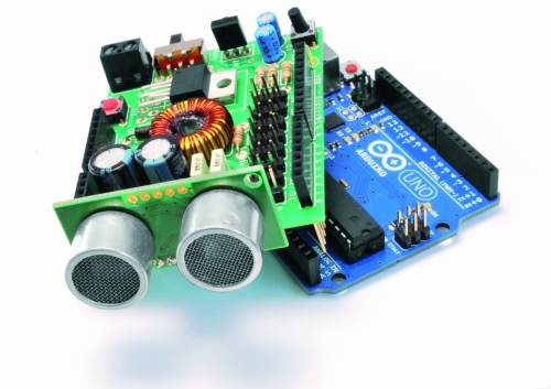
We see now the considerations that led us to the design of this shield:

        must have a high voltage range

        will provide a stabilized output for the servos

        will provide power to the Arduino

        must be equipped with an obstacle sensor

        must have a receiver for remote control

        must read the battery


We can assume to power our robot with a single battery pack with a voltage between 6 and 12 volts, so for example two cells or 6-8 LiPo NiMh or NiCd cells. The servos works at 5Volt, so we should get this stabilized voltage starting from input voltage of 6-12 volts. The optimal solution is the use of a switching step-down regulator which ensures efficiency exceeding 80% in every situation.

Just the integrated LM2576-5 contains all the elements to build a switching power supply, just add an inductor, a diode and a capacitor. It can deliver a maximum current of 3A and accepts input voltages between 4 and 40volt.


Analysing the wiring diagram you can see the connector BAT which will connect the battery pack to the switch and the voltage regulator LM2576, the resistance R5 and the led LD1 are used only to detect the presence of the voltage. The stabilized voltage output from the LM2576 will be used to power all the servos, while the Arduino is powered directly from the battery pack, taking the tension just after the switch (Vin).

For reading the battery voltage will use an analog input of Arduino (A0). The two resistors R1 and R2 reduce the voltage to a value between 0 and 20 volts to a value of 0-5Volt. We chose these specific values of resistance because, by reading the analog voltage with Arduino, it is sufficient to divide the data acquired by 50 to obtain the value of the voltage in volts.
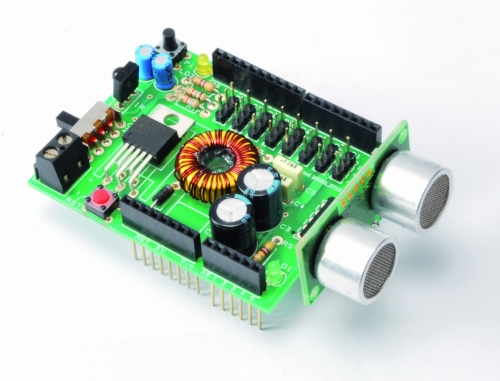
As obstacle sensor we chose the ultrasonic sensor model SRF05 that, thanks to its shape, recalls two eyes and improves the aesthetic appearance of our robot. To operate, we use a digital line connected to PIN11.

As remote control we opt for a economical infrared system; is sufficient to install an IR receiver compatible with the normal commercial remote controls, such as the integrated PNA4602. It will be sufficient a normal remote control of those used for TVs or VCRs to send commands to our robot in a simple and economic way. The shield provides the Arduino reset button, a button for general use and a LED connected to pin 13 of Arduino.


BOM

R1: 56 kohm
R2: 18 kohm
R3: 470 ohm
R4: 100 ohm
R5: 470 ohm

C1: 10 µF 63 VL
C2: 470 µF 25 VL
C3: 1000 µF 16 VL
C4: 100 nF
C5: 100 nF
C6: 10 µF 63 VL

LD1: LED 3 mm red
LD2: LED 3 mm green

U1: LM2576-5

SW1: switch

P1: Microswitch
RST: Microswitch

IR: IR38DM

L1: 100 µH 2A

D1: 1N5819

SRF05: SRF05


The Robot are three, corresponding to the robots Filippo, Bipe and Spider.
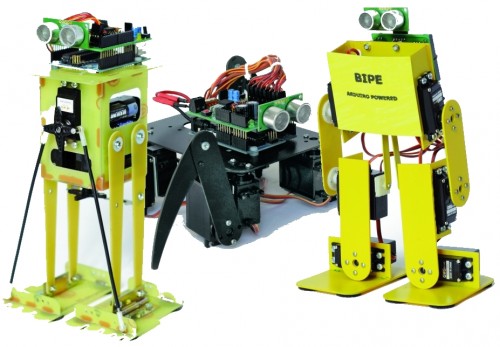
 

Filippo robot

Filippo is a biped robot whose movements are assigned to only two servos, but with this robot you can experiment with robotics without spending large sums. It is able to walk and turn around, then you can direct it in any direction, enabling those who are beginning to become familiar with the servos and how they can interact with mechanical parts. Its assembly is facilitated because all the pieces fit over each other and it is sufficient sorder to fix them permanently, as an alternative you can use the epoxy glue.
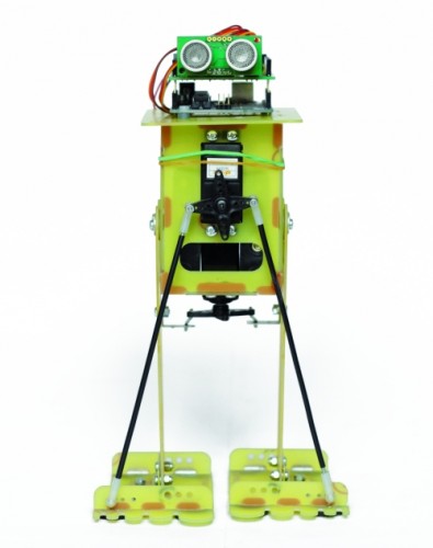
 

After the mechanical assembly, fix the Arduino board, with its shield, on top, the sensor SRF05 must look in front of the robot. The servos have to be wired as indicated in Table.


Connecting servos with Filippo robot

Servo

Arduino Pin Connector shiled Role
Servo 0 2 S1 Tilt (front servo)
Servo 1 3 S2 Step (servo in the bottom)


For the power use 6 or 8 NiCd or NiMh rechargeable batteries size AA, they should be entered in two separate holder and connected in series.  The battery holder are positioned one on the right and one on the left of the two servos, for their wiring must use two clips for batteries connected in series to 9 V.
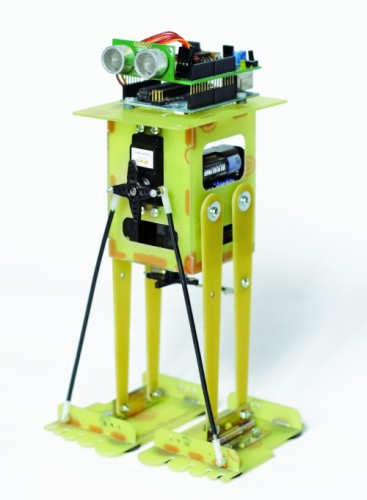
We recommend you to program the Arduino before connecting the servos to prevent any previous program provides the wrong signals to the servos that might go crazy.


Program Arduino with the sketch

// FILIPPO ARDUINO
// by Segatello Mirco per ElettronicaIN 
// compilato con Arduino21

#include <Servo.h> 
#include <IRremote.h> 
#include <EEPROM.h>

#define RECV_PIN 10   // pin per sensore IR
#define PING_PIN 11   // pin per sensore RADAR
#define       P1 12   // pin per pulsante

#define STNB_CODE1 0x81D    // Stop Philips TV remote (AZIONE STOP)
#define STNB_CODE2 0x1D     // Codice alternativo
#define WALK_CODE1 0x81C    // Play Philips TV remote (AZIONE CAMMINA)
#define WALK_CODE2 0x1C     // Codice alternativo
#define SPEEDUP_CODE1 0x820 // Prg+ Philips TV remote (AZIONE PIù VELOCE)
#define SPEEDUP_CODE2 0x20  // Codice alternativo
#define SPEEDDW_CODE1 0x821 // Prg- Philips TV remote (AZIONE PIù LENTA))
#define SPEEDDW_CODE2 0x21  // Codice alternativo
#define LEFT_CODE1    0x2C  // Left Philips remote (RUOTA SX)
#define LEFT_CODE2    0x82C  // Codice alternativo
#define RIGHT_CODE1    0x2B  // Right Philips remote (ROUTA DX)
#define RIGHT_CODE2    0x82B  // Codice alternativo

#define MODE_OFF       0    // Servi OFF
#define MODE_STANDBY   1    // Servi armati in posizione di riposo
#define MODE_INWALK    2    // Assume la posizione di partenza
#define MODE_WALK      3    // Cammina in avanti
#define MODE_INSTANDBY 4    // Assume la posizione di standby
#define MODE_LEFT      5    // Si gira verso sinistra
#define MODE_RIGHT     6    // Si gira a destra
#define MODE_REVWALK   7    // Cammina all'indietro

IRrecv irrecv(RECV_PIN);
decode_results results;

int RobotMode = MODE_OFF;   
int TimeOneStep = 2000;     // Velocità di esecuzione
int AmpPasso = 30;          // Ampiezza del passo (da 5 a 40)
int IncPasso = 15;          // Inlinazione durante la camminata (da 5 a 20)
int AmpRuota = 30;          // Ampiezza delle gambe durante la rotazione (da 5 a 40)
int IncRuota = 18;          // Inclinazione durante la rotazione (da 5 a 20)

Servo servo0, servo1;       // oggetti servo

int leg_ntr[8] = {90, 90};  //posizione neutrale dei servi
int leg_old[8] = {90, 90};  //posizione precedente dei servi
int leg[8];                 //posizione attuale dei servi
int i;

void setup() 
{ 
  Serial.begin(9600);       // Start seriale
  Serial.println("FILIPPO Aduino V1.0");
  irrecv.enableIRIn();      // Start ricevitore IR  
  irrecv.blink13(true);     // Lampeggio LED in ricezione IR attivo
  pinMode(P1, INPUT);       // Pulsante 
  digitalWrite(P1, HIGH);   // Abilita pull-up
  levelBat();               // Verifica stato batteria  
  Serial.println("Livello batteria OK.");  
  Serial.println("Recupero dati posizione neutro servi...");
  readNeutral();
  Serial.println("Inizializzo Servi...");  
  initServo();              // Inizializza servi
  Serial.println("Invia 'obs' per testare il sensore di ostacoli");
  Serial.println("Invia 'lev' per testare il livello della batteria"); 
  inStandby();              // Robot in attesa di comando  
} 

void loop() 
{ 
  if (irrecv.decode(&results)) IRcommand();
  if (RobotMode==MODE_WALK)   walk();
  if (RobotMode==MODE_LEFT)   leftWalk();  
  if (RobotMode==MODE_RIGHT)   rightWalk();

  if (digitalRead(P1)==0) P1Press(); 

  if (RobotMode==MODE_STANDBY) 
  {
    if (Serial.available() > 2 )  ReceiveData();  
  }  
  else 
  {  
    // verifica livello batteria e presenza ostacoli
    levelBat();    
    int obstacle = readDistance();    
    if (obstacle < 20){
      Serial.println("Rilevato ostacolo!");   
      inStandby();  }
  }  
} 

void readNeutral()
{
  // Recupera dalla EEPROM la posizione neutrale dei servi
  byte value;
  Serial.print("Neutro dei Servi: ");      
  for (byte adress=0; adress<2; adress++) 
  {
     value = EEPROM.read(adress);
     if ((80<value) && (value<100))
     {
          leg_ntr[adress] = value;
          Serial.print(value, DEC);
          Serial.print("  ");
     }     
     else     
     {
       leg_ntr[adress] = 90;
     }  
   }
   Serial.println();
}  

void ReceiveData() 
{
    // Arrivati dati dalla USB
    byte startbyte, data_hight, data_low, data;    
    Serial.print("Receive data USB     "); 
    startbyte = Serial.read();
    data_hight = Serial.read();    
    data_low= Serial.read();
    // richiesta livello batteria
    if ( (startbyte=='l') && (data_hight=='e') && (data_low=='v'))
    {
      levelBat();     
      Serial.flush();  // svuota il buffer in ricezione  
      exit;
    }
    // richiesta distanza ostacolo
    if ( (startbyte=='o') && (data_hight=='b') && (data_low=='s'))
    {
      int obstacle = readDistance();
      Serial.print("Ostacolo a ");
      Serial.print(obstacle, DEC);    
      Serial.println(" cm");
      if (obstacle<20)  inStandby();  
      Serial.flush();  // svuota il buffer in ricezione 
      exit;
    }    
    // impostazione neutro servo
    if ((data_hight >= '0') && (data_hight <= '9') && (data_low >= '0') && (data_low <= '9')) {      
      data = (data_hight-48)*10+(data_low-48);
      if ((80 <= data) && (data <= 100)) {
         if (startbyte=='a') {
           leg_ntr[0] = data;
           EEPROM.write(0, data);
           printValue('a', data);
         }  
         if (startbyte=='b') {
           leg_ntr[1] = data;
           EEPROM.write(1, data);
           printValue('b', data);           
         }
      inStandby();         // aggiorna posizione neutro dei servi
      }
    }
    Serial.flush();  // svuota il buffer in ricezione   
}  

void printValue(byte servo, byte dt)
{
  Serial.print ("Set Servo: ");
  Serial.print (servo);
  Serial.print (" to ");
  Serial.println(dt,DEC);        
}  

void IRcommand()
{
    // E' arrivato un comando via IR
    Serial.print("IR code= ");
    Serial.println(results.value, HEX);  // ECO su serial monitor per sapere il codice arrivato

    if (results.value == WALK_CODE1 || results.value == WALK_CODE2)  inWalk();
    else if (results.value == LEFT_CODE1 || results.value == LEFT_CODE2)  inLeft();     
    else if (results.value == RIGHT_CODE1 || results.value == RIGHT_CODE2)  inRight();       
    else if (results.value == STNB_CODE1 || results.value == STNB_CODE2)  inStandby();   

    else if (results.value == SPEEDUP_CODE1 || results.value == SPEEDUP_CODE2) {
      if (TimeOneStep > 1000) TimeOneStep -= 500; }
    else if (results.value == SPEEDDW_CODE1 || results.value == SPEEDDW_CODE2) {
      if (TimeOneStep < 4000) TimeOneStep += 500; }
    Serial.print("TimeOneStep= ");      
    Serial.println(TimeOneStep);
    irrecv.resume(); // Resume decoding   
}  

void P1Press()
{
  // E' stato premuto il pulsante   
  while (digitalRead(P1)==0) delay(100);  
  if (RobotMode==MODE_WALK)  inStandby();            
  else if (RobotMode==MODE_STANDBY) inWalk(); 
}  

void levelBat()
{
  // controllo livello batteria  
  int VbatRAW = analogRead(A0);
  float Vbat = float(VbatRAW)/50;
  Serial.print("Vbat= ");
  Serial.println(Vbat, DEC);     
  if (Vbat<6.0)   {
    Serial.println("Livello batteria basso!");    
    inOff();    
  }  
}

void initServo()  
{
  // posizione iniziale dei servi
  servo0.attach(2);  // connette servo 
  delay(200);
  servo1.attach(3);  // connette servo 
  delay(200);    
  Serial.println("Servi inizializzati.");  
}

void inOff()
{
  // Spegne tutti i servi
  leg[0] = leg_ntr[0];
  leg[1] = leg_ntr[1]; 
  setServo();  
  servo0.detach();  // sconnette servo 
  servo1.detach();  // sconnette servo 
  RobotMode = MODE_OFF;     
  // Da questo modalità si deve spegnere il robot e ricaricare le batterie
}  

void inStandby()
{
  // Posiziono tutti i servi in posizione neutrale
  leg[0] = leg_ntr[0];
  leg[1] = leg_ntr[1];      
  setServo();  
  RobotMode = MODE_STANDBY;  
  Serial.println("Sono in Standby...");  
}  

void inWalk()
{
  // Si porta in posizione di passo partendo da fermo  
  leg[0] = leg_ntr[0]+IncPasso;//inclinazione
  leg[1] = leg_ntr[1];
  setServo();  

  RobotMode = MODE_WALK;
  Serial.println("Walk Mode...");   
}

void walk()
{
  // Coordinate per eseguire un passo  
  leg[0] = leg_ntr[0]+IncPasso;//piede SX in avanti
  leg[1] = leg_ntr[1]+AmpPasso;
  setServo();  

  leg[0] = leg_ntr[0]-IncPasso;//inclinazione
  leg[1] = leg_ntr[1]+AmpPasso;       
  setServo();   

  leg[0] = leg_ntr[0]-IncPasso;//passo DX
  leg[1] = leg_ntr[1]-AmpPasso;  
  setServo();

  leg[0] = leg_ntr[0]+IncPasso;//inclinazione
  leg[1] = leg_ntr[1]-AmpPasso;       
  setServo();         
}

void inLeft()
{
  // Si porta in posizione per ruotare  
  leg[0] = leg_ntr[0]+IncRuota;//inclinazione
  leg[1] = leg_ntr[1];
  setServo();         

  RobotMode = MODE_LEFT;
  Serial.println("Left Mode...");   
}

void leftWalk()
{
      //passo 1      
  leg[0] = leg_ntr[0]+IncRuota;//fa un passo
  leg[1] = leg_ntr[1]-AmpRuota;      
  setServo();        

      //passo 2      
  leg[0] = leg_ntr[0];//piedi paralleli
  leg[1] = leg_ntr[1]-AmpRuota;      
  setServo();   

      //passo 3      
  leg[0] = leg_ntr[0];//sforbiciata
  leg[1] = leg_ntr[1]+AmpRuota;     
  setServo(); 

      //passo 4      
  leg[0] = leg_ntr[0]-IncRuota;//inclinazione
  leg[1] = leg_ntr[1]+AmpRuota;     
  setServo();    

      //passo 5      
  leg[0] = leg_ntr[0]-IncRuota;//passo
  leg[1] = leg_ntr[1]-AmpRuota;     
  setServo();         

       //passo 6      
  leg[0] = leg_ntr[0];//piedi paralleli
  leg[1] = leg_ntr[1]-AmpRuota;     
  setServo();       

      //passo 7      
  leg[0] = leg_ntr[0];//sforbiciata
  leg[1] = leg_ntr[1]+AmpRuota;     
  setServo();      

      //passo 8      
  leg[0] = leg_ntr[0]+IncRuota;//sforbiciata
  leg[1] = leg_ntr[1]+AmpRuota;     
  setServo();     
}

void inRight()
{  
  // Si porta in posizione per ruotare  
      //passo 0  inclinazione
  leg[0] = leg_ntr[0]+IncRuota;
  leg[1] = leg_ntr[1];
  setServo();         

  RobotMode = MODE_RIGHT;
  Serial.println("Right Mode...");   
}

void rightWalk()
{
      //passo 1  passo    
  leg[0] = leg_ntr[0]+IncRuota;
  leg[1] = leg_ntr[1]+AmpRuota;      
  setServo();        

      //passo 2 piedi paralleli     
  leg[0] = leg_ntr[0];
  leg[1] = leg_ntr[1]+AmpRuota;      
  setServo();   

      //passo 3  sforbiciata    
  leg[0] = leg_ntr[0];
  leg[1] = leg_ntr[1]-AmpRuota;     
  setServo();

      //passo 4 inclinazione     
  leg[0] = leg_ntr[0]-IncRuota;
  leg[1] = leg_ntr[1]-AmpRuota;     
  setServo();    

      //passo 5  passo    
  leg[0] = leg_ntr[0]-IncRuota;
  leg[1] = leg_ntr[1]+AmpRuota;     
  setServo();         

       //passo 6 piedi paralleli     
  leg[0] = leg_ntr[0];
  leg[1] = leg_ntr[1]+AmpRuota;     
  setServo();       

      //passo 7 sforbiciata
  leg[0] = leg_ntr[0];
  leg[1] = leg_ntr[1]-AmpRuota;     
  setServo();         

      //passo 8 inclinazione     
  leg[0] = leg_ntr[0]+IncRuota;
  leg[1] = leg_ntr[1]-AmpRuota;     
  setServo();   
} 

void setServo() 
{  
   // Posiziona i servi alle coordinate specificate da leg[]  
   for (i=0; i<18; i++) {
       servo0.write(leg_old[0] + i*(leg[0]-leg_old[0])/18);  
       servo1.write(leg_old[1] + i*(leg[1]-leg_old[1])/18);        
       delay(TimeOneStep/4/18);
    }   
    leg_old[0]=leg[0];
    leg_old[1]=leg[1];       
}

long readDistance()
{
  // Procedura per leggere la presenza di ostacoli
  // Viene generato un PING di 2usec ed atteso l'ECO di risposta
  long duration, cm;
  pinMode(PING_PIN, OUTPUT);
  digitalWrite(PING_PIN, LOW);
  delayMicroseconds(2);
  digitalWrite(PING_PIN, HIGH);
  delayMicroseconds(5);
  digitalWrite(PING_PIN, LOW);

  // Lo stesso pin che genera il trigger è usato per la lettura
  // del segnale di ritorno
  pinMode(PING_PIN, INPUT);
  duration = pulseIn(PING_PIN, HIGH);

  // ritorna distanza ostacolo in cm
  return duration / 29 / 2;
}

Send the serial command ‘obs‘ for read the sensor SRF05 and the command ‘lev‘ to check the battery level. Make sure that the voltage read corresponds to the real value of the batteries, simply make a voltage measurement with a multimeter. Now set the neutral of the servos, in fact the robot to function properly must be perfectly centered. To center the servo which acts to tilt the robot you have to send the command ‘axx‘ where xx is the position. This data can assume values between 80 and 100 with the center point 90, if you can not set the servo to remain within these values you have to physically move the servo. You can modify this value if it found a tendency to deviate from the straight line when walking. Now regulate the step servo and sets the neutral with bxx command, where xx is the position to be allocated (value between 80 and 100). You are now ready for test, you can use the remote control to activate functions or use the button on the shield but it will only start the walk.


All functions have a speed of execution that can be changed by remote control with keys prog+ and prog-, many other parameters can be modified to adapt the software to different operating requirements.

The sketch begins by including the libraries dedicated to the use of the servos, the IR control and management of EEPROM:


Code 1

#include <Servo.h>
#include <IRremote.h>
#include <EEPROM.h>


The servo library is already implemented in the IDE of Arduino.

The EEPROM library, also available, provides controls to manage the non-volatile memory, we use it to save the position of the neutral servos so as not having to set each time.

The third library IRremote is used to manage the robot by remote control and must be downloaded from http://github.com/shirriff/Arduino-IRremote, for its operation is sufficient to specify which pin is connected to the sensor receiving IR signals (D10 in our shield). To find out if they arrived from the sensor data must test the status of the variable irrecv.decode (& results), but the code is contained in the variable came results.value.

Just compare the code recived with the reference code for the remote to know which button was pressed, so we specify at the beginning of the sketch of the codes for each button.


Code 2

#define STNB_CODE1 0x81D    // Stop Philips TV remote (STOP)
#define STNB_CODE2 0x1D     // alternative code
#define WALK_CODE1 0x81C    // Play Philips TV remote (WALK)
#define WALK_CODE2 0x1C // alternative code
#define SPEEDUP_CODE1 0x820 // Prg+ Philips TV remote (+ SPEED)
#define SPEEDUP_CODE2 0x20  // alternative code
#define SPEEDDW_CODE1 0x821 // Prg- Philips TV remote (-SPEED)
#define SPEEDDW_CODE2 0x21  // alternative code
#define LEFT_CODE1    0x2C  // Left Philips remote (SX wheel)
#define LEFT_CODE2    0x82C  // alternative code
#define RIGHT_CODE1    0x2B  // Right Philips remote (DX wheel)
#define RIGHT_CODE2    0x82B  // alternative code


As you can see each button is associated with two codes (CODE1 and CODE2) this is because the codes are sent alternately every time you press the button, instead of repeating the same code if the button is pressed. So if you press the play button will send the code 0x81C and so long as the button is pressed, if you release the button and press it sends the code 0x1C, so alternately.

The sketch is intended for use with remote controls which use the encoding Philips, the most commonly used in television. If you use a different remote control the code of the buttons do not match and you have to change the codes listed above.

Now let’s see what parameters can be modified by the program to adapt the movements:


Code 3

int TimeOneStep = 2000;    
int AmpPasso = 30;         
int IncPasso = 15;         
int AmpRuota = 30;       
int IncRuota = 18;


TimeOneStep is the initial value of the time taken to perform a step, can be changed by remote control from a minimum of 1 sec to a maximum of 4 sec.

AmpPasso is the maximum amplitude in degrees of opening of the legs during walking, its value can vary from a minimum of 5 to a maximum of 40.

IncPasso is the maximum inclination of the robot during the walk, its value can vary from a minimum of 5 to a maximum of 20. This value is to ensure the robot to keep balance on one leg while performing a step.

AmpRuota is the maximum amplitude in degrees of opening of the legs during the rotation, its value can change from a minimum of 5 to a maximum of 40.

IncRuota is the maximum inclination of the robot during the rotation, its value can change from a minimum of 5 to a maximum of 20.


ROBOT BIPE

We see now to the second robot, is called BIPE.

The mechanical is made of PCB and assembly is made by soding together the various components to ensure the strength needed to support the weight of the components.

The control board based on Arduino + shield is positioned on the back of the robot while the battery pack, should be placed at the front. Let’s say that for our tests we used a battery composed of two cell 850mAh LiPo which, being small and light, are easily placed and not weigh down the structure. To properly position the sensor SRF05 you must use a small adapter with a strip made of male-female, as those used on the Arduino shield, angled 90 °.

Connecting servos with robot BIPE

Servo Arduino Pin Connector shield Function
Servo 0 2 S1 left hip
Servo 1 3 S2 left knee
Servo 2 4 S3 left foot
Servo 3 5 S4 right hip
Servo 4 6 S5 right knee
Servo 5 7 S6 right foot


For setting follow the same instructions for the robot Filippo, the sketch retains the same structure of the software used with Filippo, with the necessary modifications and add.


// BIPE ARDUINO
// by Segatello Mirco per ElettronicaIN 
// compilato con Arduino21

#include <Servo.h> 
#include <IRremote.h> 
#include <EEPROM.h>

#define RECV_PIN 10   // pin per sensore IR
#define PING_PIN 11   // pin per sensore RADAR
#define       P1 12   // pin per pulsante

#define STNB_CODE1 0x81D    // Stop Philips TV remote
#define STNB_CODE2 0x1D     // Codice alternativo
#define WALK_CODE1 0x81C    // Play Philips TV remote
#define WALK_CODE2 0x1C     // Codice alternativo
#define SPEEDUP_CODE1 0x820 // Prg+ Philips TV remote
#define SPEEDUP_CODE2 0x20  // Codice alternativo
#define SPEEDDW_CODE1 0x821 // Prg- Philips TV remote
#define SPEEDDW_CODE2 0x21  // Codice alternativo
#define LEFT_CODE1    0x2C  // Left Philips remote
#define LEFT_CODE2    0x82C  // Codice alternativo
#define RIGHT_CODE1    0x2B  // Right Philips remote
#define RIGHT_CODE2    0x82B  // Codice alternativo
#define VOLUP_CODE1   0x810 // Volume+
#define VOLUP_CODE2   0x10  // codice alternativo
#define VOLDW_CODE1   0x811 //Volume-
#define VOLDW_CODE2   0x11 //codice alternativo

#define PRG1_CODE1 0x801 // Program 1
#define PRG1_CODE2 0x1 // Program 1
#define PRG2_CODE1 0x802 // Program 2
#define PRG2_CODE2 0x2 // Program 2

#define MODE_OFF       0    // Servi OFF
#define MODE_STANDBY   1    // Servi armati in posizione di riposo
#define MODE_INWALK    2    // Assume la posizione di partenza
#define MODE_WALK      3    // Cammina in avanti
#define MODE_INSTANDBY 4    // Assume la posizione di standby
#define MODE_LEFT      5    // Si gira verso sinistra
#define MODE_RIGHT     6    // Si gira a destra
#define MODE_REVWALK   7    // Cammina all'indietro

IRrecv irrecv(RECV_PIN);
decode_results results;

int RobotMode = MODE_OFF;   
int TimeOneStep = 4000;     // Velocità di esecuzione
int AmpPasso = 10;          // Ampiezza del passo (da 5 a 20)
int AmpRuota = 12;          // Ampiezza durante la rotazione (da 5 a 20)
int IncPasso = 8;           // Inlinazione durante la camminata (da 5 a 10)

Servo servo0, servo1, servo2, servo3,
      servo4, servo5, servo6, servo7;  // oggetti servo
      // Servo 6 e 7 possono essere usati per le braccia!

int leg_ntr[8] = {90, 90, 90, 90, 90, 90, 90, 90}; //posizione neutrale dei servi
int leg_old[8] = {90, 90, 90, 90, 90, 90, 90, 90}; //posizione precedente dei servi
int leg[8];                 //posizione attuale dei servi
int i;

void setup() 
{ 
  Serial.begin(9600);       // Start seriale
  Serial.println("SIDERIN Aduino V1.0");
  irrecv.enableIRIn();      // Start ricevitore IR  
  irrecv.blink13(true);     // Lampeggio LED in ricezione IR attivo
  pinMode(P1, INPUT);       // Pulsante 
  digitalWrite(P1, HIGH);   // Abilita pull-up
  levelBat();               // Verifica stato batteria  
  Serial.println("Livello batteria OK.");  
  Serial.println("Recupero dati posizione neutro servi...");
  readNeutral();
  Serial.println("Inizializzo Servi...");  
  initServo();              // Inizializza servi
  Serial.println("Invia 'obs' per testare il sensore di ostacoli");
  Serial.println("Invia 'lev' per testare il livello della batteria"); 
  inStandby();              // Robot in attesa di comando  
} 

void loop() 
{ 
  if (irrecv.decode(&results)) IRcommand();
  if (RobotMode==MODE_WALK)   walk();
//  if (RobotMode==MODE_REVWALK) walkReverse();
  if (RobotMode==MODE_LEFT)   leftWalk();  
  if (RobotMode==MODE_RIGHT)   rightWalk();

  if (digitalRead(P1)==0) P1Press(); 

  if (RobotMode==MODE_STANDBY) 
  {
    if (Serial.available() > 2 )  ReceiveData();  
  }  
  else 
  {  
    levelBat();    
    int obstacle = readDistance();    
    if (obstacle < 20)  inStandby();  
  }  
} 

void readNeutral()
{
  // Recupera dalla EEPROM la posizione neutrale dei servi
  byte value;
  Serial.print("Neutro dei Servi: ");      
  for (byte adress=0; adress<6; adress++) 
  {
     value = EEPROM.read(adress);
     if ((80<value) && (value<100))
     {
          leg_ntr[adress] = value;
          Serial.print(value, DEC);
          Serial.print("  ");
     }     
     else     
     {
       leg_ntr[adress] = 90;
     }  
   }
   Serial.println();
}  

void ReceiveData() 
{
    // Arrivati dati dalla USB
    byte startbyte, data_hight, data_low, data;    
    Serial.print("Receive data USB     "); 
    startbyte = Serial.read();
    data_hight = Serial.read();    
    data_low= Serial.read();
    // richiesta livello batteria
    if ( (startbyte=='l') && (data_hight=='e') && (data_low=='v'))
    {
      levelBat();     
      Serial.flush();  // svuota il buffer in ricezione  
      exit;
    }
    // richiesta distanza ostacolo
    if ( (startbyte=='o') && (data_hight=='b') && (data_low=='s'))
    {
      int obstacle = readDistance();
      Serial.print("Ostacolo a ");
      Serial.print(obstacle, DEC);    
      Serial.println(" cm");
      if (obstacle<20)  inStandby();  
      Serial.flush();  // svuota il buffer in ricezione 
      exit;
    }    
    // impostazione neutro servo
    if ((data_hight >= '0') && (data_hight <= '9') && (data_low >= '0') && (data_low <= '9')) {      
      data = (data_hight-48)*10+(data_low-48);
      if ((80 <= data) && (data <= 100)) {
         if (startbyte=='a') {
           leg_ntr[0] = data;
           EEPROM.write(0, data);
           printValue('a', data);
         }  
         if (startbyte=='b') {
           leg_ntr[1] = data;
           EEPROM.write(1, data);
           printValue('b', data);           
         }
         if (startbyte=='c') {
           leg_ntr[2] = data;
           EEPROM.write(2, data);
           printValue('c', data);                  
         }  
         if (startbyte=='d') {
           leg_ntr[3] = data;
           EEPROM.write(3, data);
           printValue('d', data);                    
         }  
         if (startbyte=='e') {
           leg_ntr[4] = data;
           EEPROM.write(4, data);
           printValue('e', data);                   
         }
         if (startbyte=='f') {
           leg_ntr[5] = data;
           EEPROM.write(5, data);
           printValue('f', data);                   
         }
      inStandby();         // aggiorna posizione neutro dei servi
      }
    }
    Serial.flush();  // svuota il buffer in ricezione   
}  

void printValue(byte servo, byte dt)
{
  Serial.print ("Set Servo: ");
  Serial.print (servo);
  Serial.print (" to ");
  Serial.println(dt,DEC);        
}  

void IRcommand()
{
    // E' arrivato un comando via IR
    Serial.println(results.value, HEX);  // ECO su serial monitor per sapere il codice arrivato

    if (results.value == WALK_CODE1 || results.value == WALK_CODE2)   inWalk();     
    else if (results.value == LEFT_CODE1 || results.value == LEFT_CODE2)  inLeft();     
    else if (results.value == RIGHT_CODE1 || results.value == RIGHT_CODE2)  inRight();       
    else if (results.value == STNB_CODE1 || results.value == STNB_CODE2)  inStandby();   

    else if (results.value == PRG1_CODE1 || results.value == PRG1_CODE2) {
      if (RobotMode==MODE_STANDBY) kick(); }

    else if (results.value == PRG2_CODE1 || results.value == PRG2_CODE2)  {
       if (RobotMode==MODE_STANDBY)  bow(); }

    else if (results.value == SPEEDUP_CODE1 || results.value == SPEEDUP_CODE2) {
      if (TimeOneStep > 1000) TimeOneStep -= 200; }
    else if (results.value == SPEEDDW_CODE1 || results.value == SPEEDDW_CODE2) {
      if (TimeOneStep < 2000) TimeOneStep += 200; }
    Serial.print("TimeOneStep= ");      
    Serial.println(TimeOneStep);
    irrecv.resume(); // Resume decoding   
}  

void P1Press()
{
  // E' stato premuto il pulsante   
  while (digitalRead(P1)==0) delay(100);  
  if (RobotMode==MODE_WALK)  inStandby();            
  else if (RobotMode==MODE_STANDBY) inWalk(); 
}  

void levelBat()
{
  // controllo livello batteria  
  int VbatRAW = analogRead(A0);
  float Vbat = float(VbatRAW)/50;
  Serial.print("Vbat= ");
  Serial.println(Vbat, DEC);     
  if (Vbat<6.0)   {
    Serial.println("Livello batteria basso!");    
    inOff();    
  }  
}

void initServo()  
{
  // posizione iniziale dei servi
  servo0.attach(2);  // connette servo 
  delay(200);
  servo1.attach(3);  // connette servo 
  delay(200);  
  servo2.attach(4);  // connette servo 
  delay(200);
  servo3.attach(5);  // connette servo 
  delay(200);  
  servo4.attach(6);  // connette servo 
  delay(200);
  servo5.attach(7);  // connette servo 
  delay(200);  
  servo6.attach(8);  // connette servo 
  delay(200);
  servo7.attach(9);  // connette servo 
  delay(200);  
  Serial.println("Servi inizializzati.");  
}

void inOff()
{
  // Spegne tutti i servi
  leg[0] = leg_ntr[0];
  leg[1] = leg_ntr[1];
  leg[2] = leg_ntr[2];
  leg[3] = leg_ntr[3];
  leg[4] = leg_ntr[4];
  leg[5] = leg_ntr[5];   
  leg[6] = 90;
  leg[7] = 90;    
  setServo();  
  servo0.detach();  // sconnette servo 
  servo1.detach();  // sconnette servo 
  servo2.detach();  // sconnette servo 
  servo3.detach();  // sconnette servo 
  servo4.detach();  // sconnette servo 
  servo5.detach();  // sconnette servo 
  servo6.detach();  // sconnette servo 
  servo7.detach();  // sconnette servo   
  RobotMode = MODE_OFF;     
  // Da questo modalità si deve spegnere il robot e ricaricare le batterie
}  

void inStandby()
{
  // Posiziono tutti i servi in posizione neutrale
  leg[0] = leg_ntr[0];
  leg[1] = leg_ntr[1];
  leg[2] = leg_ntr[2];
  leg[3] = leg_ntr[3];
  leg[4] = leg_ntr[4];
  leg[5] = leg_ntr[5];
  leg[6] = 90;
  leg[7] = 90;      
  setServo();  
  RobotMode = MODE_STANDBY;  
  Serial.println("Sono in Standby...");  
}  

void inWalk()
{
  // Si porta in posizione di passo partendo da fermo  
  leg[0] = leg_ntr[0];//inclinazione
  leg[1] = leg_ntr[1];
  leg[2] = leg_ntr[2]-IncPasso;
  leg[3] = leg_ntr[3];
  leg[4] = leg_ntr[4];
  leg[5] = leg_ntr[5]-IncPasso*2;  
  setServo();    
  leg[0] = leg_ntr[0]+AmpPasso;//passo DX da fermo
  leg[1] = leg_ntr[1]+AmpPasso;
  leg[2] = leg_ntr[2]-IncPasso;
  leg[3] = leg_ntr[3]+AmpPasso;
  leg[4] = leg_ntr[4]+AmpPasso;
  leg[5] = leg_ntr[5]-IncPasso*2;      
  setServo();
  RobotMode = MODE_WALK;
  Serial.println("Walk Mode...");   
}

void setServo() 
{  
   // Posiziona i servi alle coordinate specificate da leg[]  
   for (i=0; i<18; i++) {
       servo0.write(leg_old[0] + i*(leg[0]-leg_old[0])/18);  
       servo1.write(leg_old[1] + i*(leg[1]-leg_old[1])/18);        
       servo2.write(leg_old[2] + i*(leg[2]-leg_old[2])/18);  
       servo3.write(leg_old[3] + i*(leg[3]-leg_old[3])/18);      
       servo4.write(leg_old[4] + i*(leg[4]-leg_old[4])/18);  
       servo5.write(leg_old[5] + i*(leg[5]-leg_old[5])/18);        
       servo6.write(leg_old[6] + i*(leg[6]-leg_old[6])/18);  
       servo7.write(leg_old[7] + i*(leg[7]-leg_old[7])/18);    
       delay(TimeOneStep/4/18);
    }   
    leg_old[0]=leg[0];
    leg_old[1]=leg[1]; 
    leg_old[2]=leg[2];
    leg_old[3]=leg[3];  
    leg_old[4]=leg[4];
    leg_old[5]=leg[5]; 
    leg_old[6]=leg[6];
    leg_old[7]=leg[7];       
}  

void      setServoWalk()
{
};   

void walk()
{
  // Coordinate per eseguire un passo
  leg[0] = leg_ntr[0]+AmpPasso;//inclinazione
  leg[1] = leg_ntr[1]+AmpPasso;
  leg[2] = leg_ntr[2]+IncPasso*2;
  leg[3] = leg_ntr[3]+AmpPasso;
  leg[4] = leg_ntr[4]+AmpPasso;
  leg[5] = leg_ntr[5]+IncPasso;       
  setServo();  
  if (RobotMode!=MODE_WALK) return;  

  leg[0] = leg_ntr[0]-AmpPasso;//passo SX
  leg[1] = leg_ntr[1]-AmpPasso;
  leg[2] = leg_ntr[2]+IncPasso*2;
  leg[3] = leg_ntr[3]-AmpPasso;
  leg[4] = leg_ntr[4]-AmpPasso;
  leg[5] = leg_ntr[5]+IncPasso;  
  setServo();
  if (RobotMode!=MODE_WALK) return;

  leg[0] = leg_ntr[0]-AmpPasso;//inclinazione
  leg[1] = leg_ntr[1]-AmpPasso;
  leg[2] = leg_ntr[2]-IncPasso;
  leg[3] = leg_ntr[3]-AmpPasso;
  leg[4] = leg_ntr[4]-AmpPasso;
  leg[5] = leg_ntr[5]-IncPasso*2;  
  setServo();
  if (RobotMode!=MODE_WALK) return;

  leg[0] = leg_ntr[0]+AmpPasso;//passo DX
  leg[1] = leg_ntr[1]+AmpPasso;
  leg[2] = leg_ntr[2]-IncPasso;
  leg[3] = leg_ntr[3]+AmpPasso;
  leg[4] = leg_ntr[4]+AmpPasso;
  leg[5] = leg_ntr[5]-IncPasso*2;      
  setServo();        
}

void inLeft()
{
  // Si posiziona pronto per girare a sinistra   
  leg[0] = leg_ntr[0];//inclinazione SX
  leg[1] = leg_ntr[1];
  leg[2] = leg_ntr[2]-IncPasso;
  leg[3] = leg_ntr[3];
  leg[4] = leg_ntr[4];
  leg[5] = leg_ntr[5]-IncPasso*2;    
  setServo();    

  leg[0] = leg_ntr[0];//piede DX avanti
  leg[1] = leg_ntr[1];
  leg[2] = leg_ntr[2]-IncPasso;
  leg[3] = leg_ntr[3]+AmpRuota;
  leg[4] = leg_ntr[4]+AmpRuota;
  leg[5] = leg_ntr[5]-IncPasso*2;       
  setServo(); 

  leg[0] = leg_ntr[0];//inclinazione DX
  leg[1] = leg_ntr[1];
  leg[2] = leg_ntr[2]+IncPasso*2;
  leg[3] = leg_ntr[3]+AmpRuota;
  leg[4] = leg_ntr[4]+AmpRuota;
  leg[5] = leg_ntr[5]+IncPasso;        
  setServo();

  leg[0] = leg_ntr[0]+AmpRuota;//piede SX indietro
  leg[1] = leg_ntr[1]+AmpRuota;
  leg[2] = leg_ntr[2]+IncPasso*2;
  leg[3] = leg_ntr[3]+AmpRuota;
  leg[4] = leg_ntr[4]+AmpRuota;
  leg[5] = leg_ntr[5]+IncPasso;      
  setServo();     

  leg[0] = leg_ntr[0]+AmpRuota;//piedi a terra
  leg[1] = leg_ntr[1]+AmpRuota;
  leg[2] = leg_ntr[2];
  leg[3] = leg_ntr[3]+AmpRuota;
  leg[4] = leg_ntr[4]+AmpRuota;
  leg[5] = leg_ntr[5];      
  setServo();       

  RobotMode = MODE_LEFT;
  Serial.println("Left Mode...");   
}

void leftWalk()
{
      //passo 1      
  leg[0] = leg_ntr[0]-AmpRuota;//sforbiciata
  leg[1] = leg_ntr[1]-AmpRuota;
  leg[2] = leg_ntr[2];
  leg[3] = leg_ntr[3]-AmpRuota;
  leg[4] = leg_ntr[4]-AmpRuota;
  leg[5] = leg_ntr[5];      
  setServo();       
      if (RobotMode!=MODE_LEFT) return;   

      //passo 2      
  leg[0] = leg_ntr[0]-AmpRuota;//inclinazione
  leg[1] = leg_ntr[1]-AmpRuota;
  leg[2] = leg_ntr[2]-IncPasso;
  leg[3] = leg_ntr[3]-AmpRuota;
  leg[4] = leg_ntr[4]-AmpRuota;
  leg[5] = leg_ntr[5]-IncPasso*2;      
  setServo();   
      if (RobotMode!=MODE_LEFT) return;

      //passo 3      
  leg[0] = leg_ntr[0]-AmpRuota;//sposta piede DX in avanti
  leg[1] = leg_ntr[1]-AmpRuota;
  leg[2] = leg_ntr[2]-IncPasso;
  leg[3] = leg_ntr[3]+AmpRuota;
  leg[4] = leg_ntr[4]+AmpRuota;
  leg[5] = leg_ntr[5]-IncPasso*2;      
  setServo();
      if (RobotMode!=MODE_LEFT) return; 

      //passo 4      
  leg[0] = leg_ntr[0]-AmpRuota;//inclinazione
  leg[1] = leg_ntr[1]-AmpRuota;
  leg[2] = leg_ntr[2]+IncPasso*2;
  leg[3] = leg_ntr[3]+AmpRuota;
  leg[4] = leg_ntr[4]+AmpRuota;
  leg[5] = leg_ntr[5]+IncPasso;      
  setServo();
      if (RobotMode!=MODE_LEFT) return;

      //passo 5      
  leg[0] = leg_ntr[0]+AmpRuota;//sposta SX indietro
  leg[1] = leg_ntr[1]+AmpRuota;
  leg[2] = leg_ntr[2]+IncPasso*2;
  leg[3] = leg_ntr[3]+AmpRuota;
  leg[4] = leg_ntr[4]+AmpRuota;
  leg[5] = leg_ntr[5]+IncPasso;      
  setServo();
      if (RobotMode!=MODE_LEFT) return;

      //passo 6
  leg[0] = leg_ntr[0]+AmpRuota;//piedi a terra
  leg[1] = leg_ntr[1]+AmpRuota;
  leg[2] = leg_ntr[2];
  leg[3] = leg_ntr[3]+AmpRuota;
  leg[4] = leg_ntr[4]+AmpRuota;
  leg[5] = leg_ntr[5];      
  setServo();  
     if (RobotMode!=MODE_LEFT) return;
}

void inRight()
{
  // Si posiziona pronto per girare a sinistra   
  leg[0] = leg_ntr[0];//inclinazione SX
  leg[1] = leg_ntr[1];
  leg[2] = leg_ntr[2]+IncPasso*2;
  leg[3] = leg_ntr[3];
  leg[4] = leg_ntr[4];
  leg[5] = leg_ntr[5]+IncPasso;    
  setServo();    

  leg[0] = leg_ntr[0]-AmpRuota;//piede DX avanti
  leg[1] = leg_ntr[1]-AmpRuota;
  leg[2] = leg_ntr[2]+IncPasso*2;
  leg[3] = leg_ntr[3];
  leg[4] = leg_ntr[4];
  leg[5] = leg_ntr[5]+IncPasso;       
  setServo(); 

  leg[0] = leg_ntr[0]-AmpRuota;//inclinazione DX
  leg[1] = leg_ntr[1]-AmpRuota;
  leg[2] = leg_ntr[2]-IncPasso;
  leg[3] = leg_ntr[3];
  leg[4] = leg_ntr[4];
  leg[5] = leg_ntr[5]-IncPasso*2;        
  setServo();

  leg[0] = leg_ntr[0]-AmpRuota;//piede SX indietro
  leg[1] = leg_ntr[1]-AmpRuota;
  leg[2] = leg_ntr[2]-IncPasso;
  leg[3] = leg_ntr[3]-AmpRuota;
  leg[4] = leg_ntr[4]-AmpRuota;
  leg[5] = leg_ntr[5]-IncPasso*2;      
  setServo();     

  leg[0] = leg_ntr[0]-AmpRuota;//piedi a terra
  leg[1] = leg_ntr[1]-AmpRuota;
  leg[2] = leg_ntr[2];
  leg[3] = leg_ntr[3]-AmpRuota;
  leg[4] = leg_ntr[4]-AmpRuota;
  leg[5] = leg_ntr[5];      
  setServo();       

  RobotMode = MODE_RIGHT;
  Serial.println("Right Mode...");   
}

void rightWalk()
{
      //passo 1      
  leg[0] = leg_ntr[0]+AmpRuota;//sforbiciata
  leg[1] = leg_ntr[1]+AmpRuota;
  leg[2] = leg_ntr[2];
  leg[3] = leg_ntr[3]+AmpRuota;
  leg[4] = leg_ntr[4]+AmpRuota;
  leg[5] = leg_ntr[5];      
  setServo();       
      if (RobotMode!=MODE_RIGHT) return;   

      //passo 2      
  leg[0] = leg_ntr[0]+AmpRuota;//inclinazione
  leg[1] = leg_ntr[1]+AmpRuota;
  leg[2] = leg_ntr[2]+IncPasso*2;
  leg[3] = leg_ntr[3]+AmpRuota;
  leg[4] = leg_ntr[4]+AmpRuota;
  leg[5] = leg_ntr[5]+IncPasso;      
  setServo();   
      if (RobotMode!=MODE_RIGHT) return;

      //passo 3      
  leg[0] = leg_ntr[0]+AmpRuota;//sposta piede DX in avanti
  leg[1] = leg_ntr[1]+AmpRuota;
  leg[2] = leg_ntr[2]+IncPasso*2;
  leg[3] = leg_ntr[3]-AmpRuota;
  leg[4] = leg_ntr[4]-AmpRuota;
  leg[5] = leg_ntr[5]+IncPasso;      
  setServo();
      if (RobotMode!=MODE_RIGHT) return; 

      //passo 4      
  leg[0] = leg_ntr[0]+AmpRuota;//inclinazione
  leg[1] = leg_ntr[1]+AmpRuota;
  leg[2] = leg_ntr[2]-IncPasso;
  leg[3] = leg_ntr[3]-AmpRuota;
  leg[4] = leg_ntr[4]-AmpRuota;
  leg[5] = leg_ntr[5]-IncPasso*2;      
  setServo();
      if (RobotMode!=MODE_RIGHT) return;

      //passo 5      
  leg[0] = leg_ntr[0]-AmpRuota;//sposta SX indietro
  leg[1] = leg_ntr[1]-AmpRuota;
  leg[2] = leg_ntr[2]-IncPasso;
  leg[3] = leg_ntr[3]-AmpRuota;
  leg[4] = leg_ntr[4]-AmpRuota;
  leg[5] = leg_ntr[5]-IncPasso*2;      
  setServo();
      if (RobotMode!=MODE_RIGHT) return;

      //passo 6
  leg[0] = leg_ntr[0]-AmpRuota;//piedi a terra
  leg[1] = leg_ntr[1]-AmpRuota;
  leg[2] = leg_ntr[2];
  leg[3] = leg_ntr[3]-AmpRuota;
  leg[4] = leg_ntr[4]-AmpRuota;
  leg[5] = leg_ntr[5];      
  setServo();         
      if (RobotMode!=MODE_RIGHT) return;  
} 

void bow()
{
  //inchino
  leg[0] = leg_ntr[0]-60;
  leg[1] = leg_ntr[1]-10;
  leg[2] = leg_ntr[2];
  leg[3] = leg_ntr[3]+60;
  leg[4] = leg_ntr[4]+10;
  leg[5] = leg_ntr[5];  
  setServo();    
  delay(1000);
  leg[0] = leg_ntr[0];//passo DX da fermo
  leg[1] = leg_ntr[1];
  leg[2] = leg_ntr[2];
  leg[3] = leg_ntr[3];
  leg[4] = leg_ntr[4];
  leg[5] = leg_ntr[5];      
  setServo();    
}  

void kick()
{
   //calcio 
  leg[0] = leg_ntr[0];//inclinazione
  leg[1] = leg_ntr[1];
  leg[2] = leg_ntr[2]-12;//regolare questo valore per bilanciare
  leg[3] = leg_ntr[3];
  leg[4] = leg_ntr[4];
  leg[5] = leg_ntr[5]-24;  
  setServo();    
  leg[0] = leg_ntr[0];//piede indietro
  leg[1] = leg_ntr[1];
  leg[2] = leg_ntr[2]-12;//regolare questo valore per bilanciare
  leg[3] = leg_ntr[3]-AmpPasso;
  leg[4] = leg_ntr[4]+AmpPasso;
  leg[5] = leg_ntr[5];  
  setServo();       
  //calcia 

       leg_old[3]=leg_ntr[3]+AmpPasso; 
       servo3.write(leg_old[3]);      
       leg_old[4]=leg_ntr[4]-AmpPasso;        
       servo4.write(leg_old[4]);  

  leg[0] = leg_ntr[0];//ritorna in posizione
  leg[1] = leg_ntr[1];
  leg[2] = leg_ntr[2];
  leg[3] = leg_ntr[3];
  leg[4] = leg_ntr[4];
  leg[5] = leg_ntr[5];      
  setServo();  

}  

long readDistance()
{
  // Procedura per leggere la presenza di ostacoli
  // Viene generato un PING di 2usec ed atteso l'ECO di risposta
  long duration, cm;
  pinMode(PING_PIN, OUTPUT);
  digitalWrite(PING_PIN, LOW);
  delayMicroseconds(2);
  digitalWrite(PING_PIN, HIGH);
  delayMicroseconds(5);
  digitalWrite(PING_PIN, LOW);

  // Lo stesso pin che genera il trigger è usato per la lettura
  // del segnale di ritorno
  pinMode(PING_PIN, INPUT);
  duration = pulseIn(PING_PIN, HIGH);

  // ritorna distanza ostacolo in cm
  return duration / 29 / 2;
}


For this robot is important to the calibration of the neutral of the servos that occurs as previously described.  Servo0 corresponds to the letter ‘a‘ – Servo5 corresponds to the letter ‘f‘. If the command is ok will receive confirmation of Serial Monitor, for example: “set servo: a to 90“.
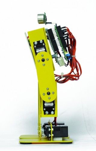


This robot have additional functions such as the bow and football features that are not implemented on Filippo.


Code 4

#define PRG1_CODE1 0x801 // Program 1
#define PRG1_CODE2 0x1 // Program 1
#define PRG2_CODE1 0x802 // Program 2
#define PRG2_CODE2 0x2 // Program 2


To the button ’1 ‘corresponds to the function of football with which the robot can hit, for example a ball, to the button ’2′ corresponds to the bow that is always of great effect.

The parameters can be set by the program are similar to those of robot Filippo:


Code 5

int TimeOneStep = 4000;  
int AmpPasso = 10;         
int AmpRuota = 12;         
int IncPasso = 8;


SPIDER ROBOT

With this robot we wanted to replicate the appearance and movements of a spider with all the limitations derived from a simplified mechanics and a limited cost.  The choice has been the use of two servos for paw for a total of four legs, which, however, ensure a final result very attractive. The largest number of servos relative to the robot BIPE should not scare because, at the end, this robot is the most simple to make and having regard to the intrinsic stability, does not present serious problems even in the operation. For this robot we have not even provided the adjustment of the neutral servos because of some inaccuracies should not be to influence the operation.The only care is to fix the battery pack in the center so the robots present the center of gravity exactly in the center. During the movement three legs always remain in contact with the ground while one moves, rising, thereby ensuring a good stability.

The mechanical is made by PCB, the same material used for printed electronic and suggest paint it black to improve the aesthetic appearance. No soldering required, and each piece is simply screwed to the servos that make up the mechanics.
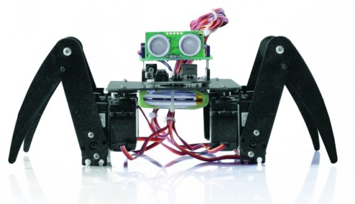
How practical advice suggest to program the Arduino board with this program and then electrically connecting the servos, doing so will all be positioned exactly in the middle.Then you connect the mechanical servos in their proper locations.

// SPIDER ARDUINO
// by Segatello Mirco for ElettronicaIN 
// Compilato con Arduino21

#include <Servo.h> 
#include <IRremote.h> 

#define RECV_PIN 10   // pin per sensore IR
#define PING_PIN 11   // pin per sensore RADAR
#define       P1 12   // pin per pulsante

#define STNB_CODE1 0x81D    // Stop Philips TV remote
#define STNB_CODE2 0x1D     // Codice alternativo
#define WALK_CODE1 0x81C    // Play Philips TV remote
#define WALK_CODE2 0x1C     // Codice alternativo
#define SPEEDUP_CODE1 0x820 // Prg+ Philips TV remote
#define SPEEDUP_CODE2 0x20  // Codice alternativo
#define SPEEDDW_CODE1 0x821 // Prg- Philips TV remote
#define SPEEDDW_CODE2 0x21  // Codice alternativo
#define LEFT_CODE1    0x2C  // Left Philips remote
#define LEFT_CODE2    0x82C  // Codice alternativo
#define RIGHT_CODE1    0x2B  // Left Philips remote
#define RIGHT_CODE2    0x82B  // Codice alternativo

#define MODE_OFF       0    // Servi OFF
#define MODE_STANDBY   1    // Servi armati in posizione di riposo
#define MODE_INWALK    2    // Assume la posizione di partenza
#define MODE_WALK      3    // Cammina in avanti
#define MODE_INSTANDBY 4    // Assume la posizione di standby
#define MODE_LEFT      5    // Si gira verso sinistra
#define MODE_RIGHT     6    // Si gira a destra
#define MODE_REVWALK   7    // Cammina all'indietro

IRrecv irrecv(RECV_PIN);
decode_results results;

int RobotMode = MODE_OFF;   
int TimeOneStep = 6000;     // Tempo in msec per eseguire un passo completo

Servo servo0, servo1, servo2, servo3,
      servo4, servo5, servo6, servo7;  // oggetti servo

int leg_old[8] = {90, 90, 90, 90, 90, 90, 90, 90}; //posizione precedente dei servi
int leg[8];                 //posizione attuale dei servi
int i;

void setup() 
{ 
  Serial.begin(9600);       // Start seriale
  Serial.println("BIPE Aduino V1.0");
  irrecv.enableIRIn();      // Start ricevitore IR  
  irrecv.blink13(true);     // Lampeggio LED in ricezione IR attivo
  pinMode(P1, INPUT);       // Pulsante 
  digitalWrite(P1, HIGH);   // Abilita pull-up
  levelBat();               // Verifica stato batteria  
  Serial.println("Livello batteria OK.");  
  Serial.println("Inizializzo Servi...");  
  initServo();              // Inizializza servi
  Serial.println("Servi inizializzati.");
  inStandby();              // Robot in attesa di comando
} 

void loop() 
{ 
  if (irrecv.decode(&results)) IRcommand();
  if (RobotMode==MODE_WALK)   walk();
  if (RobotMode==MODE_REVWALK) walkReverse();
  if (RobotMode==MODE_LEFT)   leftWalk();  
  if (RobotMode==MODE_RIGHT)   rightWalk();
  levelBat();  
  if (RobotMode==MODE_STANDBY) delay(100); 
  if (digitalRead(P1)==0) P1Press();  

  int obstacle = readDistance();
  Serial.print("Ostacolo: ");
  Serial.println(obstacle, DEC);    
  if (obstacle<20)  inStandby();    

  // Ricezione seriale per setup servi
  if (Serial.available()) SerialSet();  
} 

void SerialSet()
{
   // E' arrivato un comando dalla seriale
  byte c;
  byte srv;

  while(Serial.available())     // finchè ci sono dati 
  {
      c = Serial.read();    // legge i dati e li salva in una variabile
      if ( 97 <= c <= 102)   Serial.print(c);
 }  
}

void IRcommand()
{
    // E' arrivato un comando via IR
    Serial.println(results.value, HEX);  // ECO su serial monitor per sapere il codice arrivato

    if (results.value == WALK_CODE1 || results.value == WALK_CODE2)   inWalk();     
    else if (results.value == LEFT_CODE1 || results.value == LEFT_CODE2)  inLeft();     
    else if (results.value == RIGHT_CODE1 || results.value == RIGHT_CODE2)  inRight();       
    else if (results.value == STNB_CODE1 || results.value == STNB_CODE2)  inStandby();            
    else if (results.value == SPEEDUP_CODE1 || results.value == SPEEDUP_CODE2) {
      if (TimeOneStep > 1000) TimeOneStep -= 500; }
    else if (results.value == SPEEDDW_CODE1 || results.value == SPEEDDW_CODE2) {
      if (TimeOneStep < 6000) TimeOneStep += 500; }
    Serial.print("TimeOneStep= ");      
    Serial.println(TimeOneStep);
    irrecv.resume(); // Resume decoding   
}  

void P1Press()
{
  // E' stato premuto il pulsante   
  while (digitalRead(P1)==0) delay(100);  
  if (RobotMode==MODE_WALK)  inStandby();            
  else if (RobotMode==MODE_STANDBY) inWalk(); 
}  

void levelBat()
{
  // controlla livello batteria  
  int VbatRAW = analogRead(A0);
  float Vbat = float(VbatRAW)/50;
  Serial.print("Vbat= ");
  Serial.println(Vbat, DEC);     
  if (Vbat<6.0)   {
    Serial.println("Livello batteria basso!");    
    inOff();    
  }  
}

void initServo()  
{
  // posizione iniziale dei servi
  servo0.attach(2);  // connette servo 
  delay(300);
  servo1.attach(3);  // connette servo 
  delay(300);  
  servo2.attach(4);  // connette servo 
  delay(300);
  servo3.attach(5);  // connette servo 
  delay(300);  
  servo4.attach(6);  // connette servo 
  delay(300);
  servo5.attach(7);  // connette servo 
  delay(300);  
  servo6.attach(8);  // connette servo 
  delay(300);
  servo7.attach(9);  // connette servo 
  delay(300);     
}

void inOff()
{
  // Spegne tutti i servi
  leg[0] = 90;
  leg[1] = 90;
  leg[2] = 90;
  leg[3] = 90;
  leg[4] = 90;
  leg[5] = 90;
  leg[6] = 90;
  leg[7] = 90;      
  setServo();  
  servo0.detach();  // connette servo 
  servo1.detach();  // connette servo 
  servo2.detach();  // connette servo 
  servo3.detach();  // connette servo 
  servo4.detach();  // connette servo 
  servo5.detach();  // connette servo 
  servo6.detach();  // connette servo 
  servo7.detach();  // connette servo 
  RobotMode = MODE_OFF;     
  // Da questo modalità si deve spegnere il robot e ricaricare le batterie
}  

void inStandby()
{
  // Posiziono tutti i servi al centro
  leg[0] = 90;
  leg[1] = 90;
  leg[2] = 90;
  leg[3] = 90;
  leg[4] = 90;
  leg[5] = 90;
  leg[6] = 90;
  leg[7] = 90;      
  setServo();  
  RobotMode = MODE_STANDBY;  
  Serial.println("Sono in Standby...");  
}  

void inWalk()
{
  // Si alza pronto per partire   
  leg[0] = 99;
  leg[1] = 126;
  leg[2] = 117;
  leg[3] = 54;
  leg[4] = 99;
  leg[5] = 126;
  leg[6] = 117;
  leg[7] = 54;      
  setServo();  
  RobotMode = MODE_WALK;
  Serial.println("Walk Mode...");   
}

void setServo() 
{  
   // Posiziona i servi alle cordinate specificate da leg[]  
   for (i=0; i<18; i++) {
       servo0.write(leg_old[0] + i*(leg[0]-leg_old[0])/18);  
       servo1.write(leg_old[1] + i*(leg[1]-leg_old[1])/18);        
       servo2.write(leg_old[2] + i*(leg[2]-leg_old[2])/18);  
       servo3.write(leg_old[3] + i*(leg[3]-leg_old[3])/18);      
       servo4.write(leg_old[4] + i*(leg[4]-leg_old[4])/18);  
       servo5.write(leg_old[5] + i*(leg[5]-leg_old[5])/18);        
       servo6.write(leg_old[6] + i*(leg[6]-leg_old[6])/18);  
       servo7.write(leg_old[7] + i*(leg[7]-leg_old[7])/18);    
       delay(TimeOneStep/4/18);
    }   
    leg_old[0]=leg[0];
    leg_old[1]=leg[1]; 
    leg_old[2]=leg[2];
    leg_old[3]=leg[3];  
    leg_old[4]=leg[4];
    leg_old[5]=leg[5]; 
    leg_old[6]=leg[6];
    leg_old[7]=leg[7];       
}  

void setServoWalk() 
{     
   // Posiziona i servi durante la camminata 
   for (i=1; i<=18; i++) {
       servo0.write(leg_old[0] + i*(leg[0]-leg_old[0])/18);          
       servo2.write(leg_old[2] + i*(leg[2]-leg_old[2])/18);       
       servo4.write(leg_old[4] + i*(leg[4]-leg_old[4])/18);       
       servo6.write(leg_old[6] + i*(leg[6]-leg_old[6])/18);  

      // servi delle zampe
         if ( i <= 9 ) 
           servo1.write(leg_old[1] + i*(leg[1]-leg_old[1])/9);         
         else  
           servo1.write(leg_old[1] + (18-i)*(leg[1]-leg_old[1])/9);      

         if ( i <= 9 ) 
           servo3.write(leg_old[3] + i*(leg[3]-leg_old[3])/9);                   
         else    
           servo3.write(leg_old[3] + (18-i)*(leg[3]-leg_old[3])/9); 

         if ( i <= 9 ) 
           servo5.write(leg_old[5] + i*(leg[5]-leg_old[5])/9);         
         else  
           servo5.write(leg_old[5] + (18-i)*(leg[5]-leg_old[5])/9);    

         if ( i <= 9 ) 
           servo7.write(leg_old[7] + i*(leg[7]-leg_old[7])/9);         
         else  
           servo7.write(leg_old[7] + (18-i)*(leg[7]-leg_old[7])/9);       

       delay(TimeOneStep/4/18);
    }   
    leg_old[0]=leg[0];
    leg_old[1]=126;//leg[1]; 
    leg_old[2]=leg[2];
    leg_old[3]=54;//leg[3];  
    leg_old[4]=leg[4];
    leg_old[5]=126;//leg[5]; 
    leg_old[6]=leg[6];
    leg_old[7]=54; //leg[7];  
    if (digitalRead(P1)==0) P1Press();  
    if (irrecv.decode(&results)) IRcommand();    
}  

void walk()
{
      // Coordinate per eseguire un passo

      //passo 1      
      leg[0] = 117;
      leg[1] = 126;
      leg[2] = 63;
      leg[3] = 90;   //posizione zampa alzata
      leg[4] = 81;
      leg[5] = 126;
      leg[6] = 99;
      leg[7] = 54;  
      setServoWalk();      
      if (RobotMode!=MODE_WALK) return;

      //passo 2      
      leg[0] = 63;
      leg[1] = 90;   // posizione zampa alzata
      leg[2] = 81;
      leg[3] = 54;
      leg[4] = 63;
      leg[5] = 126;
      leg[6] = 81;
      leg[7] = 54;  
      setServoWalk();
      if (RobotMode!=MODE_WALK) return;

      //passo 3      
      leg[0] = 81;
      leg[1] = 126;
      leg[2] = 99;
      leg[3] = 54;
      leg[4] = 117;
      leg[5] = 90;    // posizione zampa alzata
      leg[6] = 63;
      leg[7] = 54;  
      setServoWalk();
      if (RobotMode!=MODE_WALK) return; 

      //passo 4      
      leg[0] = 99;
      leg[1] = 126;
      leg[2] = 117;
      leg[3] = 54;
      leg[4] = 99;
      leg[5] = 126;
      leg[6] = 117;
      leg[7] = 90;    // posizione zampa alzata
      setServoWalk();       
}

void walkReverse()
{
      //passo 1      
      leg[0] = 63;
      leg[1] = 126;
      leg[2] = 117;
      leg[3] = 90;  // si alza
      leg[4] = 99;
      leg[5] = 126;
      leg[6] = 81;
      leg[7] = 54;  
      setServoWalk();      
      if (RobotMode!=MODE_WALK) return;   

      //passo 2      
      leg[0] = 117;
      leg[1] = 126;
      leg[2] = 99;
      leg[3] = 54;
      leg[4] = 117;
      leg[5] = 90;  // si alza
      leg[6] = 99;
      leg[7] = 54;  
      setServoWalk();
      if (RobotMode!=MODE_WALK) return;

      //passo 3      
      leg[0] = 99;
      leg[1] = 126;
      leg[2] = 81;
      leg[3] = 54;
      leg[4] = 63;
      leg[5] = 126;
      leg[6] = 117;
      leg[7] = 90;  // si alza  
      setServoWalk();
      if (RobotMode!=MODE_WALK) return; 

      //passo 4      
      leg[0] = 81;
      leg[1] = 90; // si alza
      leg[2] = 63;
      leg[3] = 54;
      leg[4] = 81;
      leg[5] = 126;
      leg[6] = 63;
      leg[7] = 54;  
      setServoWalk();       
}

void inLeft()
{
  // Si alza pronto per girare a sinistra   
  leg[0] = 63;
  leg[1] = 126;
  leg[2] = 81;
  leg[3] = 54;
  leg[4] = 99;
  leg[5] = 126;
  leg[6] = 117;
  leg[7] = 54;      
  setServo();  
  RobotMode = MODE_LEFT;
  Serial.println("Left Mode...");   
}

void leftWalk()
{
      //passo 1      
      leg[0] = 81;
      leg[1] = 126;
      leg[2] = 99;
      leg[3] = 54;  
      leg[4] = 117;
      leg[5] = 126;
      leg[6] = 63;
      leg[7] = 90;//*  
      setServoWalk();      
      if (RobotMode!=MODE_LEFT) return;   

      //passo 2      
      leg[0] = 99;
      leg[1] = 126;
      leg[2] = 117;
      leg[3] = 54;
      leg[4] = 63;
      leg[5] = 90;//*
      leg[6] = 99;
      leg[7] = 54;  
      setServoWalk();
      if (RobotMode!=MODE_LEFT) return;

      //passo 3      
      leg[0] = 117;
      leg[1] = 126;
      leg[2] = 63;
      leg[3] = 90;//*
      leg[4] = 81;
      leg[5] = 126;
      leg[6] = 99;
      leg[7] = 54;   
      setServoWalk();
      if (RobotMode!=MODE_LEFT) return; 

      //passo 4      
      leg[0] = 63;
      leg[1] = 90;//*
      leg[2] = 81;
      leg[3] = 54;
      leg[4] = 99;
      leg[5] = 126;
      leg[6] = 117;
      leg[7] = 54;  
      setServoWalk();         
}

void inRight()
{
  // Si alza pronto per girare a destra   
  leg[0] = 99;
  leg[1] = 126;
  leg[2] = 117;
  leg[3] = 54;
  leg[4] = 63;
  leg[5] = 126;
  leg[6] = 81;
  leg[7] = 54;      
  setServo();  
  RobotMode = MODE_RIGHT;
  Serial.println("Right Mode...");   
}

void rightWalk()
{
      //passo 1      
      leg[0] = 81;
      leg[1] = 126;
      leg[2] = 99;
      leg[3] = 54;  
      leg[4] = 117;
      leg[5] = 90;//*
      leg[6] = 63;
      leg[7] = 54;  
      setServoWalk();      
      if (RobotMode!=MODE_RIGHT) return;   

      //passo 2      
      leg[0] = 63;
      leg[1] = 126;
      leg[2] = 81;
      leg[3] = 54;
      leg[4] = 99;
      leg[5] = 126;
      leg[6] = 117;
      leg[7] = 90;//*  
      setServoWalk();
      if (RobotMode!=MODE_RIGHT) return;

      //passo 3      
      leg[0] = 117;
      leg[1] = 90;//*
      leg[2] = 63;
      leg[3] = 54;
      leg[4] = 81;
      leg[5] = 126;
      leg[6] = 99;
      leg[7] = 54;   
      setServoWalk();
      if (RobotMode!=MODE_RIGHT) return; 

      //passo 4      
      leg[0] = 99;
      leg[1] = 126;
      leg[2] = 117;
      leg[3] = 90;//*
      leg[4] = 63;
      leg[5] = 126;
      leg[6] = 81;
      leg[7] = 54;  
      setServoWalk();           
} 

long readDistance()
{
  // Procedura per leggere la presenza di ostacoli
  // Viene generato un PING di 2usec ed atteso l'ECO di risposta
  long duration, cm;
  pinMode(PING_PIN, OUTPUT);
  digitalWrite(PING_PIN, LOW);
  delayMicroseconds(2);
  digitalWrite(PING_PIN, HIGH);
  delayMicroseconds(5);
  digitalWrite(PING_PIN, LOW);

  // Lo stesso pin che genera il trigger è usato per la lettura
  // del segnale di ritorno
  pinMode(PING_PIN, INPUT);
  duration = pulseIn(PING_PIN, HIGH);

  // ritorna distanza ostacolo in cm
  return duration / 29 / 2;
}

Make sure that the servos are aligned and that the legs are neither too open nor too closed, taking as reference the pictures posted here .
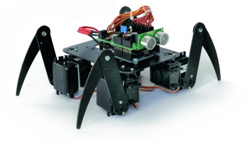


Connect the servos to the robot Spider

Servo Arduino Pin Connector shield Function
Servo 0 2 S1 Angle right foreleg
Servo 1 3 S2 Elevation of right foreleg
Servo 2 4 S3 Angle of the right hind leg
Servo 3 5 S4 Elevation of the right hind leg
Servo 4 6 S5 Angle left hind leg
Servo 5 7 S6 Elevation of the left hind paw
Servo 6 8 S7 Angle left foreleg
Servo 7 9 S8 Elevation of left foreleg


Turning on after 1 second (after the warm-up switching power supply) all the servos will be placed in the neutral point. It may happen that some servos vibrate slightly, this is due to the internal mechanism that has yet to find the center point, sometimes just a small blow to the servant to fix things.

For this robot we never anticipated that you can edit parameters, movements are many and complex and there are too many variables to set, we preferred to find a setup that could offer the best performance in every situation. For our prototype LiPo battery that powers it has been established under the structure, right through to the servos, ensuring, in addition to the centering of weight, a low center of gravity.

Let us see now the analysis of the firmware describing those functions that are common to all the robots such as the procedure that reads the distance from obstacles by means of the sensor SRF05:


Code 6

long readDistance()
{
  long duration, cm;
  pinMode(PING_PIN, OUTPUT);
  digitalWrite(PING_PIN, LOW);
  delayMicroseconds(2);
  digitalWrite(PING_PIN, HIGH);
  delayMicroseconds(5);
  digitalWrite(PING_PIN, LOW);
  pinMode(PING_PIN, INPUT);
  duration = pulseIn(PING_PIN, HIGH);
  // ritorna distanza ostacolo in cm
  return duration / 29 / 2;
}

The procedure foresees to send a pulse duration of 2usec to the sensor, which, proceeds generating a series of ultrasound to the outside. The same pin is subsequently used as input for reading, via the function PulseIn, the time taken by the sound to reach the obstacle, bounce and return to the sensor, the period during which the sensor maintains a high level of the line. The time taken by the ultrasound to go and return to the sensor is proportional to the distance of the object.


Here also the procedure for reading the voltage on the battery:


Code 7

void levelBat()
{
  int VbatRAW = analogRead(A0);
  float Vbat = float(VbatRAW)/50;
  Serial.print("Vbat= ");
  Serial.println(Vbat, DEC);    
  if (Vbat<6.0)   {
    Serial.println("Livello batteria basso!");   
    inOff();   
  } 
}


The procedure is simple, plan to read the analog channel A0 of Arduino and save the result into a variable VbatRAW. As explained above, by dividing this value by 50, is obtained by the voltage in volts of the battery. Since excessively discharge the battery can damage it, we expected an alarm to the level below which the robot is immediately stopped and all the servos are disabled.  The threshold value is defined in 6.0 V ideal for use with a battery pack consisting of two cell LiPo or six if you use NiMh or NiCd cells, eight cells used instead if you can increase this value up to 8.0 volts or, one volt per used cell.


Another common procedure is called to all the robots initServo () to initialize the servos:


Code 8

void initServo() 
{
  // posizione iniziale dei servi
  servo0.attach(2);  // connette servo
  delay(300);
........
  servo7.attach(9);  // connette servo
  delay(300);    
}


The function Servo.attach() associates each object provides the respective servo output, from this moment the servant reaches the PWM signal.


The procedure inOff () performs the opposite function by removing the pin from their association with the servos and leaving them with no control.


Code 9

void inOff()
{
  leg[0] = 90;
.....
  leg[7] = 90;     
  setServo(); 
  servo0.detach();  // connette servo
....
  servo7.detach();  // connette servo
  RobotMode = MODE_OFF;    
}


The function to put in sleep mode the robot is called Standby() and simply place all the servos in the central position. In the case of the robot Filippo and BIPE the servos are positioned in their respective neutral points whose values are contained in the vector named leg_ntr [].


Code 10

void inStandby()
{
  leg[0] = 90;
....
  leg[7] = 90;     
  setServo(); 
  RobotMode = MODE_STANDBY; 
  Serial.println("Sono in Standby..."); 
}


A very important procedure is to ensure that the servos have to place to desired coordinates:


Code 11

void setServo()
{ 
   for (i=0; i<18; i++) {
       servo0.write(leg_old[0] + i*(leg[0]-leg_old[0])/18); 
       servo1.write(leg_old[1] + i*(leg[1]-leg_old[1])/18);       
       servo2.write(leg_old[2] + i*(leg[2]-leg_old[2])/18); 
       servo3.write(leg_old[3] + i*(leg[3]-leg_old[3])/18);     
       servo4.write(leg_old[4] + i*(leg[4]-leg_old[4])/18); 
       servo5.write(leg_old[5] + i*(leg[5]-leg_old[5])/18);       
       servo6.write(leg_old[6] + i*(leg[6]-leg_old[6])/18); 
       servo7.write(leg_old[7] + i*(leg[7]-leg_old[7])/18);   
       delay(TimeOneStep/4/18);
    }  
    leg_old[0]=leg[0];
    leg_old[1]=leg[1];
    leg_old[2]=leg[2];
    leg_old[3]=leg[3]; 
    leg_old[4]=leg[4];
    leg_old[5]=leg[5];
    leg_old[6]=leg[6];
    leg_old[7]=leg[7];      
}


If we set directly the servo, it was a sudden movement and the robot would move in spurts. He prefers, instead, gradually controlling the servo to bring it to the desired position in a defined time. To do this you must define a vector leg[] that contains the coordinates to be achieved by each servo and a vector leg_old[] that contains the actual coordinates. The procedure controls the servos by sending them all coordinated by the intermediate value at the target value in a time defined by the variable TimeOneStep. This system allows us to obtain fluid movements.

Only the robot spider there is a procedure called setServoWalk() because it is necessary that some servos are moving at different speeds than the other. During the walk the three legs in contact with the floor moving slowly, the fourth foot must lift and move fast in the opposite direction to progress.


Download

 Gerber for Shield
   Gerber for Filippo
   Gerber for Bipe
   Gerber for Spider


-->-->-->-->-->-->
-->-->
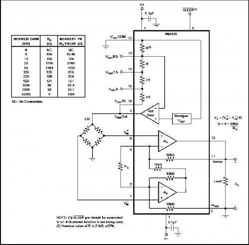
How to make an Arduino shield with Eagle CAD – Tutorial

-->-->-->-->

There are many CAD developed to assist the electronic designers during drawing of PCBs and schematics; often they are integrated in complete suite to project, simulate and realize a whole electronic system. Besides the many commercial versions, there are also free CADs available. Today we’d like to analyze one of the most diffused and known software: Eaglecad (eagle does not mean the powerful bird but it is the acronym of Easily Applicable Graphical Layout Editor) made by Cadsoft, actually at version 6.2.0. We have chosen this one because, as you know as an Arduino’s fan, the official pcbs and schematic files of the boards are developed and available free of charge to everybody in Eaglecad format; you can find also a lot of libraries and circuits made by famous DIY website (Sparkfun for first) available for free. Eaglecad is a professional software that have gained a lot of popularity due to the Arduino’s success. One of the most important difference between Eaglecad and its competitors is the availability of a version for every of the most common desktop OS: Windows, Linux, Mac. We have to specify that Eaglecad is not Free software but is a commercial one, which can be used in the free version (eaglecad light) only for evaluation purposes and by student but you can’t use the light version in any case when you earn or save money by using it. For further details about licenses and distributors have a look to the official Eaglecad website where you can find all the information you need. Remember that the light version has some limitations; anyway you can design circuit with a discrete complexity, as the one you can see at http://elmicro.com/en/kit12.html. The limitations are:

 - pcb dimensions not bigger than 100×80 mm;

 - no more than 2 layers;

 - only 1 sheet for schematic.

Now let’s have a look at the software itself starting from the GUI, which is made by three main units:

Control Panel

Schematic (you can see an Arduino’s UNO R3 board schematic screenshot)

Board (the pcb editor) which can be seen “in action” which shows the pcb of the Arduino’s R3 board


For people used to the other similar cads, the interface is very closed to them and you’ll learn to use it easily; anyway to use the most powerful functions you need some practice.

The first thing you see at the CAD start up is the Control Panel, from which you can easily get access (for example) to the libraries, projects and examples; this is the software section where you can configure the main options like user’s folders, delay for the autosave option and the most important graphical parameters, all by getting access to the “OPTIONS” menu. The available documentation is pretty complete: you can access to the help function from the “help” menu available in both “Schematic” and “Pcb”. If you need further details you have to read the complete manual and the tutorial which are both available getting access to “Start” (on Windows), Programs-> Eagle Layout Editor 6.2.0.

Let’s try to have practice with an example: we want to draw an Arduino’s shield made by 4 leds e da 4 switches, connected to 8 digital pins; it’s obvious due to the kind of circuit we are approaching to make, that this shield is only for training purposes. This pcb can be used to show the digital logic level of one or some pins, levels that could be changed by the four switches or to have a led alarm in case of an analog becomes higher or lower than some level.

For first we have to draw the schematic so we select “FILE”, “NEW”, “SCHEMATIC” in this order: the Schematic window will open up. It is mainly made by two groups of icons: one on the top with the main commands like file management and zoom and another one on the left with the “drawing” icons.


We can add the components by selecting the “AND” gate icon on the left hand side of the screen; when the cursor will be on it the word “Add” will pop up. Once selected, a list of libraries will be shown.

We can add other libraries like the Sparkfun one for example or we can also modify the ones which are provided by Eaglecad. Now select “Resistor”, “R-EU”: on the screen will appear a sub library where we can choose the kind of resistor we need (SMD,trough-hole) and its package.

For our example we’d like to use trough hole components so we’ll choose “R-EU_02_07/10″ which is a 1/4W resistor horizontally mounted. Once a component has been chosen, on the right hand side of the window, Eaglecad shows the component symbol used in the schematic and beside the pcb pads of such component and the space required on the PCB. There is another window under the two we have seen before where there are details and notes that have been inserted during creation of the selected component.

We need 4 of such components so we click on “OK”, move on the schematic drawing area and put the element where we want by clicking again. Eaglecad automatically names resistors in a progressive way.

When we have finished with these components, we have to select “ESC” on the keyboard: again the “ADD” window will open itself; now we select “LED5MM” in the “LED” sub-library which is contained into the “Led” library and we’ll draw four leds as done before.

In the same way we can select the 4 switches “10-xx” available in the library “switch-omron”; these actions lead us to the situation shown here:

For the moment we can mainly focus our attention about the correct type of the connectors so we add, as explained before, two made by 6 contacts for the power supply section and the analog connections and other two made by 8 pins for digitals; the chosen connectors are the ones in the “con-molex” library, identified by “22-23-2061″ e “22-23-2081″. Push two times ESC to exit and so far we are in the conditions show:

Now select the 4 resistors one at time, right-click and select “Value” in order to assign the desired value to each of them. Do the same with the 4 connectors, in order to change their value e.g. into A1, A2, D1, D2. A warning window with two choices will pop up: we’ll chose “Yes” and in the next window we’ll insert the required value. We’ll do the same for the next three strips.

Now below every resistors there is the resistance value and also the four connectors have been renamed as required. It is also possible to rename every singol contact of every connector. Let’s do that, in order to avoid mistakes: select “name” in the left hand column and then put the mouse cursor on every contact to replace their name, e.g. “D1″, “D2″, “A1″, “A2″.

In this way it is easy to understand for every contact which is the related connector strip. Now insert the ground symbol and connect the LED cathodes to them (Eaglecad have available many kind of ground symbols: they are in the libraries “supply1″ and “supply2″). We’ll choose “GND” available in the “supply1″ library. Looking at the digital strips we can notice that they are in the “wrong” side of the schematic. To have a more easily access to the contact connections and to have a clear and readable schematic, we can use the”mirror” command to mirror the selected parts. Before apply this command, select the symbols of both connectors with the command “group” in order to reduce the number of required actions.

Select “Mirror” and then put the mouse pointer on the working area and select by left clicking first and then by right clicking “Mirror: Group”. Now it’ s time to draw connections. We can proceed in two ways: by selecting the commands “Draw” and “Wire” in sequence or by clicking with the left mouse switch on the related icon. To connect components put the cursor on the end of the symbol you want to connect, click with the left mouse switch and move the pointer on the terminal of the other components you have to connect to and click again.

To go to the next connection push ESC on the keyboard, put the mouse pointer where you want to draw the next wire and then left click again.

So far so good. We have focused our attention on LEDs, forgetting the switches. Never mind, we can insert, modify, delete, change the inserted parts in the schematic every time we need it; now we insert the missing components adding the required connections.

As you can see it’s easy to rotate and to move any part by using the related function in the “edit” menu or by selecting the desired icon in the left hand side column.

Once all the connections are done, select “Tool”, “Erc” to solve errors, if any, which will be shown in the “Erc errors” window where Eaglecad lists some issues: leds and switches have no value and the pins of the strips are not connected.

We don’t care about the missing values because they are not important in our schematic and we know that the unconnected pins are not used in our circuit. To confirm that, select “Approve” for all the requests and then with “Tools” and “”Errors” command we make sure that there are no further issues. Finally it’s time to draw the printed circuit board: left click on the “Board” icon which is the fifth starting from the left on the tool bar which is on the top of the working window.

The system will ask us if we want to create the related file so we confirm “Yes” and then we’ll have on the screen the same picture as the one shown in figure:

Using the command “Move” which can be selected by the icon with the four arrows in the left hand column, move the components where required. It’s better to start with the connectors due to they give the dimensions to the shield. Remember that the eight and the 6 pins connectors don’t have the same “step” on the board; in case of doubt check another shield, or you can refer to the pcb of the Uno which can be easily found on the Arduino’s website. The ones who have the R3 know that the strips have been redrawn to follow the increased needs of such system so the old connectors 8+8 and 6+6 have been replaced with 10+8 for digital pins and 8+6 for analog. In our example we have chosen to use the old connectors because they are compatible with all the Arduino version between 2009 and Uno and then because our shield was born for teaching reasons so it’s better to have it compatible also with the old pcb versions which are still used by many people. To insert the four connectors we can use the grid which help us; to change its resolution get access to “View”, “Grid” or “Properties” which is available by the “i” icon; in the last case we have also information about the absolute position in the working space.

Since the versions 6 of Eagleacad it is available another function which support us during drawing: “dimension” available through “Draw->Dimension”.

Wiring routing can be done automatically (autorouting function) or manually. In this short introduction we’ll use the hand routing in order to practice with Eaglecad. By selecting the “Route” icon it is possible to draw connections; the dimension, shape and width are visible on the top icon bar where is also possible to select the pcb side. The freeware version make possible to draw pcbs with only two sides, so we’ll find only “Top” and “Bottom”. In the same way you move components it is possible to define the printed circuit board dimensions; the white lines are the cutting boarder where the CNC will cut the pcb. Finally here a possible two sides pcb of our Arduino’s shield.

Special thanks to author Vincenzo Mendola.

-->-->-->-->-->-->
-->-->
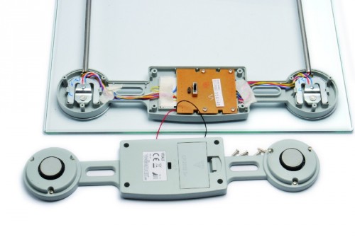
Low cost Ethernet shield with ENC28J60

Economical alternative to original Arduino ethernet shields, allows data rates up to 10 Mbps and is achieved with a traditional assembly components.

One of the most interesting shield that you can mount on the Arduino platform is certainly the ethernet shield, because enable numerous networking applications such as remote control of systems and users, web access and publication of data, and more yet, the simplicity of finding and integrating open-source libraries on Arduino IDE does the rest. The usefulness of LAN connectivity has meant that the market would respond by offering different ethernet shield, first of all the original Arduino Ethernet Shield, which was accompanied by the good shield by Seeed Studio, both of these circuits are based on the chipset WIZnet W5100, allow multiple socket connections and can work at 100 Mbps

This ethernet shield is low-cost thanks to components used: all traditional mounting (THT). This feature makes the circuit accessible to those who haven’t the equipment to assemble SMD components. The data-rate is limited to 10 Mbps.


Wiring diagram

The shield is based on a Microchip ENC28J60 chip that interfaces with Arduino and data conversion according to the ethernet protocol. It integrates the MAC controller, an 8 KB Transmit / Receive Packet Dual Port Buffer and a circular FIFO managed at the hardware level, allows the programming of data retransmission in case of collision.
The MAC controller supports both Unicast, Multicast and Broadcast packets, has a programmable 64-byte pattern within a margin allowed to the user and programmable wake-up on multiple packet formats (Magic Packet, Unicast, Multicast, Broadcast, specific packet match or any packet).


In the circuit we see that over all’ENC28J60 there are a standard RJ45 jack with integrated LEDs, filters and line transformers, and a voltage level shifter for the SPI interface to communicate with the Arduino.

MISO is the output data of the slave device and the input of Arduino, while MOSI is the opposite; SCK is the clock that marks the two-way communication on the SPI bus and RESET the reset line, which is also connected to a button that allows you to reset the Ethernet interface, if necessary, manually. The digital D10 and D2 lines of Arduino are used, respectively, for the control of CS (Chip Select, active logic zero) and the reading of INT. U3B is used to adapt the logic levels 0/3, 3 V to those of Arduino 0/5 V.

The ENC28J60 operates with a clock of 25 MHz, defined by the quartz Q1 connected between the pins 23 and 24; the capacitor connected to pin VCAP filters the output voltage (2.5 V) of the internal controller and should preferably be of the type low ESR (low series resistance parasite). The resistor connected to RBIAS is used to bias the LAN transceiver that is part of the pin TPIN + / – and TPOUT + / -.

We conclude the analysis of the circuit diagram of the shield with the power that is drawn by Arduino 5V and Vin through the strip: the first provides the 5 volts continuous stabilized points of the circuit that require them (basically the 74HC125 and the resistance of pull Line-up reset and Chip Select) and the second give power to the integrated regulator U2, which creates the 3.3 volts needed to power the microcontroller and circuits contained in the RJ45 jack.


The library for ENC28J60


The original library from which we derived can be downloaded from the site https://github.com/jcw/ethercard ; from our site you can download the library itself but with a higher number of application examples.

Here you will find a sketch example to build a Web Server, in particular, in the current web page you will see the hours: minutes: seconds elapsed from the ignition of Arduino.


// This is a demo of the RBBB running as webserver 
// with the Ether Card
// 2010-05-28 
// http://opensource.org/licenses/mit-license.php

#include

// ethernet interface mac address
static byte mymac[] = { 0x74,0x69,0x69,0x2D,0x30,0x31 };
// ethernet interface ip address
static byte myip[] = { 192,168,0,188 };
// gateway ip address
static byte gwip[] = { 192,168,0,1 };

byte Ethernet::buffer[500];
BufferFiller bfill;

void setup () {
  if (ether.begin(sizeof Ethernet::buffer, mymac) == 0)
    Serial.println( "Failed to access Ethernet controller");
  ether.staticSetup(myip);
}

static word homePage() {
  long t = millis() / 1000;
  word h = t / 3600;
  byte m = (t / 60) % 60;
  byte s = t % 60;
  bfill = ether.tcpOffset();
  bfill.emit_p(PSTR(
    "HTTP/1.0 200 OK\r\n"
    "Content-Type: text/html\r\n"
    "Pragma: no-cache\r\n"
    "\r\n"
    "<meta http-equiv='refresh' content='1'/>"
    "<title>RBBB server</title>" 
    "<h1>$D$D:$D$D:$D$D</h1>"),
      h/10, h%10, m/10, m%10, s/10, s%10);
  return bfill.position();
}

void loop () {
  word len = ether.packetReceive();
  word pos = ether.packetLoop(len);

  if (pos)  // check if valid tcp data is received
    ether.httpServerReply(homePage()); // send web page data
}


Library Ethernet shild with ENC28J60 

Store

Arduino RFID shield

This shield could be used as a stand-alone transponder key, or with Google’s servers to create a cloud-computing application.


It’s time to present you an application with RFID. We want to show you how to use the popular Arduino to produce a device capable of recognizing passive transponder (TAG). But this is not the usual RFID key, because the system can activate a relay if a recognised TAG is read, but also we took the opportunity to make an application that use cloud-computing. The basic version, which is a simple key relay consists of an Arduino (Duemilanove or UNO) and the RFID shield based on a ID-12 of Innovations: placing a transponder already learned, the relay is activated.
The extended version of our project uses an Arduino, the RFID Shield and the Ethernet Shield with which we can access the Internet and stored, using the Google Docs service, the transponder data.

The RFID shield
But before you see the applications in detail, we spend some words on the shield for Arduino that we need to capture data of passive TAG. It is a very simple circuit based on the form ID-12 , which contains a complete recognizer of passive transponders, in addition to a relay controlled by Arduino and a few other passive components. The buzzer, which allows you to set an audible alert, could be controlled by ID-12 or by Arduino.

The relay is powered by Vin Arduino (and the corresponding contact of the shield) and GND. The base of the transistor that controls RL1 is driven by the pin 9 of the Arduino. The lines 6 and 8 control the lighting of the LEDs.
In our case, the pin 7 of ID-12 is connected to ground, so the chip will only recognize ASCII coded tag and return its output in ASCII characters.

The component has a TTL level serial interface, accessible from it’s pins 9 and 8, then there is an output (pin 10) that pulses rapidly (at a frequency of 3 kHz) every time the module detects the code of a tag encoded and used to drive a buzzer or a light emitting diode.
All data are read from Arduino using the library NewsoftSerial that allows to emulate a serial port; in our case, the emulation is carried on lines 7.

How it works

Once you put power to the system, when the module ID-12 reads a tag, the pin 10 pulse at 3 kHz and the Arduino read s data; then microcontroller compares the code with those who has in memory.
If the transponder is one of those already learned the micro actives the relay and the green led. This relay will be used to control an electric lock, a gate, etc..
In bistable mode, the relay changes state each time the ID-12 reads a valid tag.
Clearly, the circuit can work well if in his memory there is at least a RFID tag.

To learn the code for a tag and then write it to EEPROM, you must press and hold button P1 for 3 seconds (max. 5), once that is done you have to pass a card and wait for the confirmation sound (given by buzzer) and light (provided by the green LED).
At any time you can remove a tag code from memory: must press the P1 button for 5 seconds or longer, until the red LED lights on. At this point you release the button and pass the tag to be deleted, if the LED turns off and on again, the card has been deleted.
To erase the entire EEPROM you must restart the Arduino, and during the reboot, hold down the button P1 for about one second; when the red LED lights up. Done this, Arduino is ready to read new tags.

R1: 330 ohm
R2: 330 ohm
R3: 4,7 kohm
R4: 10 kohm

LD1: Led 3 mm green
LD2: Led 3 mm red

BZ1: Buzzer

T1: BC547

RFID1: ID-12

RL1: Relé 12V

P1: Microswitch 90°

D1: 1N4007

Varie:
- Screw 3 poli
- Jumper (2 pz.)
- Strip male 3 via (2 pz.)
- Strip M/F 6 via (2 pz.)
- Strip M/F 8 via (2 pz.)


/* RFID shield key

 created 2011
 by Andrea Fainozzi

 This example code is in the public domain.

http://www.open-electronics.org

http://www.futurashop.it

http://blog.elettronicain.it/

 */

#include <EEPROM.h>
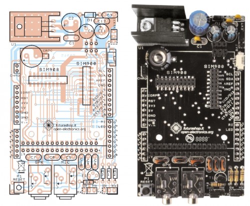
#include <NewSoftSerial.h>
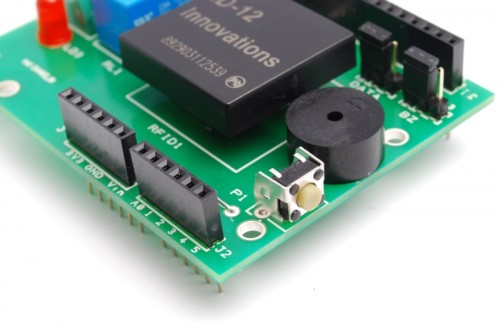
#define PULSANTE   5               //pin relativo al pulsante da premere per entrare in modalità scrittura/cancellazione

#define DATA_PIN       7           //scegliere il pin che si vuole utilizzare in base alla scelta fatta con il jumper sulla scheda (7 | 
#define RELE_PIN       9           //scegliere il pin che si vuole utilizzare in base alla scelta fatta con il jumper sulla scheda (9 | 10)
#define BUZZ_PIN       3           //scegliere il pin che si vuole utilizzare in base alla scelta fatta con il jumper sulla scheda (3 | 11)
#define GREEN_LED_PIN  8           //pin relativo al led verde
#define RED_LED_PIN    6           //pin relativo al led rosso

//scegliere cosa fare quando viene letta una scheda

#define RELE     0                 //scegliere '1' per fare in modo che alla lettura di una scheda il relè venga attivato '0' per non fare nulla
#define BUZZER   1                 //scegliere '1' per fare in modo che alla lettura di una scheda il buzzer emetta un suono '0' per non fare nulla
#define LED      1                 //scegliere '1' per fare in modo che alla lettura di una scheda corretta venga acceso il led verde e per una scheda incorretta il led rosso '0' per non fare nulla

#define DURATA_RELE 1000          //scegliere il tempo per il quale deve rimanere acceso il relè (se viene inserito '0' il relè funzionerà in modo bistabile)

boolean check;                    //variabile con la quale eseguo tutti i controlli all'interno dello sketch
int on_off=0;                     //variabile che utilizzo per controllare lo stato del led in modalità bistabile

NewSoftSerial mySerial(DATA_PIN,1);    //inizializzo il pin sul quale leggere i dati trasmessi dall'ID-12
void setup() {

  if(DURATA_RELE>60000)                                                    //controllo che il tempo impostato per la durata di attivazione del relè sia inferiore a 1 minuto
    while(1){                                                              //in caso contrario stampo su seriale un messaggio di errore in un ciclo infinito
        delay(2000);
        Serial.print("Tempo relè non valido, troppo alto");
    }

  pinMode(PULSANTE,INPUT);                                                 //imposto il pin del pulsante in modalità input per verificare quando il pulsante viene premuto
  digitalWrite(PULSANTE,HIGH);                                             //e lo setto alto, in modo tale da attivare la resistenza di pull-up

  if(RELE)                                                                 //controllo se è stato scelto di attivare o meno il relè, nel primo caso, imposto il pin assegnatogli come output
    pinMode(RELE_PIN,OUTPUT);
  if(BUZZER)                                                               //controllo se è stato scelto di attivare o meno il buzzer, nel primo caso, imposto il pin assegnatogli come output
    pinMode(BUZZ_PIN,OUTPUT);
  if(LED){                                                                 //controllo se è stato scelto di attivare o meno i led, nel primo caso, imposto i pin assegnatogli come output
    pinMode(GREEN_LED_PIN,OUTPUT);
    pinMode(RED_LED_PIN,OUTPUT);
  }
  Serial.begin(9600);                                                      //Inizializzo la porta seriale sulla frequenza di 9600 baud
  mySerial.begin(9600);                                                    //inizializzo la seriale sulla quale leggo i dati delle schede a 9600 baud

  if(digitalRead(PULSANTE)==LOW) azzera();                                 //controllo che il il pulsante sia premuto in fase di accensione del dispositivo, in caso affermativo azzero tutta la memoria EEPROM
}

void loop () {

  byte val;                                                          //variabile che utilizzo per leggere i valori dalla tessera appena passata
  byte code[6];                                                      //vettore nel quale salvo il codice letto completo
  byte checksum;                                                     //variabile sulla quale calcolo e salvo il checksum
  byte bytesread;                                                    //variabile che viene utilizzata per per contare quanti byte sono stati letti
  byte tempbyte;                                                     //variabile che mi serve per memorizzare temporaneamente mezzo byte letto

  unsigned long int tempo=0;                                         //variabile che utilizzo per salvare il tempo attuale, per contare i millisecondi passati
  boolean scrivere=false;                                            //variabile che utilizzo per controllare se la tessera appena letta è da salvare o da controllare
  boolean controllo=false;                                           //variabile che utilizzo per controllare se la tessera appena letta è da cancellare oppure no

  if(digitalRead(PULSANTE)==LOW){                                    //controllo se il pulsante è premuto
     tempo=millis();                                                 //se lo è salvo gli attuali millisecondi passati dall'avvio del dispositivo
     while((digitalRead(PULSANTE)==LOW)&&(tempo+3000>millis()));     //quindi mando in esecuzione un ciclo che non fa nulla
     if(millis()>tempo+2999){                                        //controllo dopo la fine del ciclo se esso è stato in esecuzione per 3 secondi, confrontando il tempo iniziale + 3000 con il tempo attuale
       if(LED)
         digitalWrite(GREEN_LED_PIN,HIGH);                           //se così è, accendo il led verde
         Serial.println("Modalità registrazione");                   //e stampo sulla seriale che sono entrato in modalità registrazione
       if(BUZZER){
         analogWrite(BUZZ_PIN,50);
         delay(50);                                                  //e faccio fare un suono di avviso al buzzer
         digitalWrite(BUZZ_PIN,LOW);
       }
         scrivere=true;                                              //e pongo a vero la variabile scrivere
     }
     if(digitalRead(PULSANTE)==LOW){                                 //se dopo ciò il pulsante è ancora premuto
       while((digitalRead(PULSANTE)==LOW)&&(tempo+5000>millis()));   //mando in esecuzione un altro ciclo nullo
       if(millis()>tempo+4999){                                      //se esso è stato in esecuzione per 2 secondi significa che sono entrato in modalita eliminazione
         Serial.println("Modalità eliminazione");                    //quindi lo scrivo sulla seriale
        if(LED){
         digitalWrite(RED_LED_PIN,HIGH);                             //accendo il led rosso
         digitalWrite(GREEN_LED_PIN,LOW);                            //spengo quello verde, precedentemente acceso
        }
        if(BUZZER){
         analogWrite(BUZZ_PIN,50);
         delay(50);                                                  //faccio fare un suono di avviso al buzzer
         digitalWrite(BUZZ_PIN,LOW);
        }
         while(digitalRead(PULSANTE)==LOW);                          //mando in esecuzione un ciclo finchè il pulsante non viene rilasciato
         controllo=true;                                             //e pongo a vero la variabile controllo
       }
     }
  }

//-------------------------------------------------------------------------------------inizio do-while------------------------------------------------------------------------------------------

  do{                                                                //inizio un ciclo che finirà solo quando verrà premuto nuovamente il pulsante

   val = 0;
   checksum = 0;                                                     //azzero le variabili precedentemente dichiarate
   bytesread = 0;
   tempbyte = 0;

  if(mySerial.available() > 0) {                                     //controllo se sulla mia seriale è presente qualche dato
    if((val = mySerial.read()) == 2) {                               //se così è leggo da essa il valore
      bytesread = 0;                                                 //e se è uguale a 2 (carattere di controllo) pongo a 0 la variabile bytesread
      while (bytesread < 12) {                                       //mando in esecuzione un ciclo per 12 volte, in modo da poter leggere tutti i 12 caratteri della tessera (5 byte del codice + 1 del cehcksum
      if( mySerial.available() > 0) {                                //controllo se i dati sono disponibili ad essere letti
          val = mySerial.read();                                     //quindi assegno a 'val' il valore dell'i-esimo carattere
          if((val == 0x0D)||(val == 0x0A)||(val == 0x03)||(val == 0x02)) {     //se leggo un carattere 'header' o un carattere di stop
            break;                                                             // fermo la lettura
          }

          if ((val >= '0') && (val <= '9')) {
            val -= '0';
          }                                                                    //traduco in esadecimale il carattere appena letto
          else if ((val >= 'A') && (val <= 'F')) {
            val = 10 + val - 'A';
          }

          //ogni 2 caratteri letti, aggiungo il byte così creato al vettore 'code'

          if (bytesread & 1 == 1) {                                            //se ho letto un solo carattere fin'ora
            code[bytesread >> 1] = (val | (tempbyte << 4));                        //assegno alla seconda parte del byte in posizione bytesread-esima il valore esadecimale del carattere letto

            if (bytesread >> 1 != 5) {                                             //se ho letto l'ultimo byte della scheda calcolo il checksum
              checksum ^= code[bytesread >> 1];                                    //facendo la XOR sull'ultimo byte letto
            };
          } else {
            tempbyte = val;                                                    //altrimenti assegno il valore letto alla variabile tempbyte
          };

          bytesread++;                                                        //mi preparo a leggere il prossimo byte
        }
      }

     if (bytesread == 12) {                                                   //se ho letto tutti i 6 byte
        (code[5]==checksum) ? check = true : check = false ;                  //controllo che il checksum sia corretto
        if(check){                                                            //se lo è passo a controllare se devo salvare o cancellare
            check=false;                                                      //rimetto a false la variabile check per successivi utilizzi
            if(scrivere&&!controllo){                                         //controllo se devo scrivere
                  for(int i=0;i<1021;i+=5){                                   //in caso affermativo eseguo un ciclo che controlla tutta la EEPROM
                        if((EEPROM.read(i)==code[0])&&(EEPROM.read(i+1)==code[1])&&(EEPROM.read(i+2)==code[2])&&(EEPROM.read(i+3)==code[3])&&(EEPROM.read(i+4)==code[4])){
                            check=true;                                        //se trovo il codice della tessera letta già salvato nella EEPROM metto a true la variabile 'check'
                            break;                                             //ed esco dal ciclo
                        }
                  }
                  if(check){                                                   //quindi controllo il valore della variabile check, se è vero, significa che la tessera è già stata registrata
                        Serial.print("Tessera già registrata!");               //quindi lo comunico su seriale
                        stampa_code(code);
                      if(LED)
                        digitalWrite(RED_LED_PIN,HIGH);
                        delay(50);
                      if(BUZZER)
                        analogWrite(BUZZ_PIN,50);                              //e mando un segnale di errore luminoso e/o sonoro in sempre in base al fatto che l'utente abbia specificato led e buzzer
                        delay(50);
                      if(BUZZER)
                        digitalWrite(BUZZ_PIN,LOW);
                      if(LED)
                        digitalWrite(RED_LED_PIN,LOW);
                  }

                  else{                                                        //se la tessera non è stata trovata
                      check=false;                                             //rimetto a false la variabile check per successivi utilizzi
                      for(int i=0;i<1021;i+=5){                                //quindi eseguo un ciclo che controlla tutta la EEPROM in cerca di 5 byte successivi liberi
                        if((EEPROM.read(i)==0xff)&&(EEPROM.read(i+1)==0xff)&&(EEPROM.read(i+2)==0xff)&&(EEPROM.read(i+3)==0xff)&&(EEPROM.read(i+4)==0xff)){
                          for(int j=i;j<i+5;j++)                               //una volta trovati, partendo dal primo, fino al quinto, ci salvo il valore della tessera
                              EEPROM.write(j,code[j-i]);                             //eseguendo un ciclo 5 volte
                          check=true;                                                //pongo a true la variabile check
                          break;                                               //ed esco dal ciclo
                        }
                      }
                      if(check){                                               //se la variabile check è vera, significa che ho salvato con successo, quindi
                          Serial.print("Tessera Salvata");                     //lo stampo su seriale
                          stampa_code(code);
                        if(BUZZER){
                          analogWrite(BUZZ_PIN,50);
                          delay(100);
                          digitalWrite(BUZZ_PIN,LOW);
                        }
                        if(LED){
                          for(int i=0;i<5;i++){
                           digitalWrite(GREEN_LED_PIN,HIGH);                   //e mando un segnale luminoso e/o sonoro in sempre in base al fatto che l'utente abbia specificato led e buzzer
                           delay(50);
                           digitalWrite(GREEN_LED_PIN,LOW);
                           delay(50);
                          }
                          digitalWrite(GREEN_LED_PIN,HIGH);
                        }
                      }
                      else{                                                    //se la variabile check non è vera, significa che ho controllato tutta la memoria senza trovare 5 byte sequenziali liberi
                           Serial.println("Memoria piena");                    //quindi spamo su seriale che la memoria è piena
                           for(int i=0;i<5;i++){
                           if(LED)
                             digitalWrite(RED_LED_PIN,HIGH);
                           if(BUZZER)
                             analogWrite(BUZZ_PIN,50);
                           delay(50);                                          //e mando un segnale di errore luminoso e/o sonoro in sempre in base al fatto che l'utente abbia specificato led e buzzer
                           if(LED)
                             digitalWrite(RED_LED_PIN,LOW);
                           if(BUZZER)
                             digitalWrite(BUZZ_PIN,LOW);
                           delay(50);
                          }
                    }
                }
            }
            else if(scrivere&&controllo){                                      //se non bisogna salvare, controllo se bisogna eliminare una tessera
                  int posizione=-1;                                            //quindi inizializzo a -1 la variabile posizione, che mi servirà per salvare la posizione nella EEPROM della tessera
                  for(int i=0;i<1021;i+=5){                                    //ed eseguo un ciclo che controlla tutta la EEPROM per cercare il codice corrispondente
                        if((EEPROM.read(i)==code[0])&&(EEPROM.read(i+1)==code[1])&&(EEPROM.read(i+2)==code[2])&&(EEPROM.read(i+3)==code[3])&&(EEPROM.read(i+4)==code[4])){
                            posizione=i;                                       //se viene trovato salvo la posizione del primo byte nella variabile posizione
                        break;                                                 //ed esco dal ciclo
                        }
                  }
                  if(posizione!=-1){                                           //quindi controllo che la variabile posizione sia diversa da -1 così da sapere se è stato trovato o meno il codice
                      for(int j=posizione;j<posizione+5;j++)                   //eseguo quindi un ciclo partendo dalla posizione 'posizione' nella EEPROM
                              EEPROM.write(j,0xff);                            //sovrascrivendo i 5 byte corrispondenti alla tessera, con il byte di default '0xff'
                      Serial.print("Scheda cancellata");                       //una volta fatto ciò, stampo su seriale l'avvenuta cancellazione
                      stampa_code(code);
                      if(LED){
                        digitalWrite(GREEN_LED_PIN,HIGH);
                        digitalWrite(RED_LED_PIN,HIGH);
                      }
                      if(BUZZER)
                        analogWrite(BUZZ_PIN,50);                              //e mando un segnale luminoso e/o sonoro in sempre in base al fatto che l'utente abbia specificato led e buzzer
                      delay(250);
                      if(LED)
                        digitalWrite(GREEN_LED_PIN,LOW);
                      if(BUZZER)
                        digitalWrite(BUZZ_PIN,LOW);
                  }
                  else{                                                        //se la variabile posizione vale -1 significa che non ha trovato in memoria la tessera letta
                      Serial.print("Impossibile cancellare la scheda, non è salvata");  //quindi lo comunico su seriale
                      stampa_code(code);
                      for(int x=0;x<10;x++){
                        if(LED)
                          digitalWrite(RED_LED_PIN,HIGH);
                        if(BUZZER)
                          analogWrite(BUZZ_PIN,50);
                        delay(25);                                             //e mando un segnale di errore luminoso e/o sonoro in sempre in base al fatto che l'utente abbia specificato led e buzzer
                        if(LED)
                          digitalWrite(RED_LED_PIN,LOW);
                        if(BUZZER)
                          digitalWrite(BUZZ_PIN,LOW);
                        delay(25);
                      }
                      if(LED)
                        digitalWrite(RED_LED_PIN,HIGH);
                    }

            }

            check=true;                                                        //rimetto a vero il valore della variabile check siccome il checksum è corretto
            }
            else{                                                              //se il checksum fosse incorretto
                 Serial.print("Checksum incorretto");                          //lo comunico su seriale
                 for(int i=0;i<3;i++){
                    if(LED)
                      digitalWrite(RED_LED_PIN,HIGH);
                    if(BUZZER)
                      analogWrite(BUZZ_PIN,50);
                    delay(30);                                                 //e mando un segnale di errore luminoso e/o sonoro in sempre in base al fatto che l'utente abbia specificato led e buzzer
                    if(LED)
                      digitalWrite(RED_LED_PIN,LOW);
                    if(BUZZER)
                      digitalWrite(BUZZ_PIN,LOW);
                 }
                 if(LED)
                    digitalWrite(RED_LED_PIN,HIGH);
            }

     }
    }
  }
  }
  while((digitalRead(PULSANTE)==HIGH)&&(controllo||scrivere));

//-------------------------------------------------------------------------------------------fine do-while---------------------------------------------------------------------------------------

  if(LED){
    digitalWrite(GREEN_LED_PIN,LOW);                                          //spengo gli eventuali led accesi per conoscere la modalità nella quale ero all'interno del ciclo
    digitalWrite(RED_LED_PIN,LOW);
  }

  if (bytesread == 12) {                                                      //controllo di avere letto tutti i 6 byte della tessera
     if(check){                                                               //controllo che il checksum sia corretto
           if(!scrivere){                                                     //e controllo anche che non ci sia da salvare/scrivere una tessera
                  check=false;                                                //rimetto a false la variabile check per successivi utilizzi
                  for(int i=0;i<1021;i+=5)                                    //eseguo un ciclo che controlla tutta la EEPROM alla ricerca della tessera letta
                        if(EEPROM.read(i)==code[0]&&EEPROM.read(i+1)==code[1]&&EEPROM.read(i+2)==code[2]&&EEPROM.read(i+3)==code[3]&&EEPROM.read(i+4)==code[4]){
                            check=true;                                       //se viene trovata metto a true la variabile check
                            break;                                            //ed esco dal ciclo
                        }

                     if(check){                                               //quindi controllo il valore della variabile check
                       Serial.print("Tessera valida");                        //se è vero, significa che la tessera è stata trovata e quindi è valida, e lo stampo su seriale
                       stampa_code(code);
                       if(LED)
                            digitalWrite(GREEN_LED_PIN,HIGH);
                       if(BUZZER){
                            analogWrite(BUZZ_PIN,50);
                            delay(200);
                            digitalWrite(BUZZ_PIN,LOW);                       //quindi in base alla selezione dell'utente
                       }                                                      //mando un segnale luminoso e/o sonoro
                       if(RELE){                                              //in più accendo il relè
                            if(DURATA_RELE){                                  //secondo la modalità impostata dall'utente
                               digitalWrite(RELE_PIN,HIGH);
                               tempo=millis();
                               while(tempo+DURATA_RELE>millis());
                               digitalWrite(RELE_PIN,LOW);
                            }
                            else{
                               if(on_off){
                                  digitalWrite(RELE_PIN,LOW);
                                  on_off--;
                               }
                               else{
                                  digitalWrite(RELE_PIN,HIGH);
                                  on_off++;
                               }
                            }
                       }
                    }
                      else{                                                    //se al contrario il valore è falso
                        Serial.print("Tessera non valida!");                   //significa che ho controllato tutta la memoria senza trovare la tessera, quindi lo comunico su seriale
                        stampa_code(code);
                        if(LED)
                            digitalWrite(RED_LED_PIN,HIGH);
                        if(BUZZER){
                            analogWrite(BUZZ_PIN,50);
                            delay(50);
                            digitalWrite(BUZZ_PIN,LOW);                        //e mando un segnale di errore luminoso e/o sonoro in sempre in base al fatto che l'utente abbia specificato led e buzzer
                            delay(50);
                            analogWrite(BUZZ_PIN,50);
                            delay(50);
                            digitalWrite(BUZZ_PIN,LOW);
                        }
                     }
                    }
                    if(LED){
                      delay(500);
                      digitalWrite(GREEN_LED_PIN,LOW);                         //spegno gli eventuali led rimasti accesi
                      digitalWrite(RED_LED_PIN,LOW);
                    }
     }
     else{                                                                     //se il checksum fosse incorretto
                 Serial.print("Checksum incorretto");                          //lo comunico su seriale
                 for(int i=0;i<3;i++){
                    if(LED)
                      digitalWrite(RED_LED_PIN,HIGH);
                    if(BUZZER)
                      analogWrite(BUZZ_PIN,50);
                    delay(30);                                                 //e mando un segnale di errore luminoso e/o sonoro in sempre in base al fatto che l'utente abbia specificato led e buzzer
                    if(LED)
                      digitalWrite(RED_LED_PIN,LOW);
                    if(BUZZER)
                      digitalWrite(BUZZ_PIN,LOW);
                 }
     }
    }
  bytesread=0;                                                                 //azzero la variabile bytesread per una prossima lettura
}

//--------------------------------------------------------------------------FUNZIONE PER AZZERARE LA MEMORIA EEPROM------------------------------------------------------------------------------

void azzera(){
  if(LED){
    digitalWrite(GREEN_LED_PIN,HIGH);
    digitalWrite(RED_LED_PIN,HIGH);
  }
  for(int i=0;i<1023;i++)
      EEPROM.write(i,0xff);
  Serial.println("Memoria Azzerata!");
  if(BUZZER)
    analogWrite(BUZZ_PIN,50);
  for(int i=0;i<5;i++)
    if(LED){
      digitalWrite(GREEN_LED_PIN,HIGH);
      delay(100);
      digitalWrite(GREEN_LED_PIN,LOW);
      digitalWrite(RED_LED_PIN,HIGH);
      delay(100);
      digitalWrite(RED_LED_PIN,LOW);
    }
  if(BUZZER)
    digitalWrite(BUZZ_PIN,LOW);
}

//--------------------------------------------------------------FUNZIONE PER STAMPARE IL CODICE DELLA TESSERA LETTA SU SERIALE-------------------------------------------------------------------

void stampa_code(byte * code){
        Serial.print(": <");
        for (int i=0; i<5; i++) {
          if (code[i] < 16) Serial.print("0");
          Serial.print(code[i], HEX);
          if(i!=4)
            Serial.print(" ");
        }
        Serial.println(">");
}


Send data to Google

Our system may be facing a network and on the web to secure the cooperation of the Google Docs service. It only works if we add an Ethernet Shield.
Our online application proposes to use a Google Spreadsheet document (spreadsheet on Google Docs, anyway …) in which Arduino transcribe the codes read from valid cards. The only condition for accessing the service has to be registered, or have a Google account (eg Gmail), if you have not, open it: it is free and gives you the opportunity to have a mail box and many other free services offered by Google.
In practice, our system does not directly access to the spreadsheet, but sends the data using a form (form). We write a post to explain how to connect Arduino to Google Docs. All the results of a module is imported in the corresponding sheet, from which can be viewed by authorized users, or by anyone in possession of the link, if we remove the protection.


/* RFID shield Google

 created 2011
 by Andrea Fainozzi

 This example code is in the public domain.

http://www.open-electronics.org

http://www.futurashop.it

http://blog.elettronicain.it/

 */

#include <EEPROM.h>
#include <NewSoftSerial.h>
#include <Ethernet.h>
#include <SPI.h>
#include <Client.h>

char formkey[] = "dDh11222222233333333344444444MQ"; //Chiave identificatrice del documento di google (SOSTITUIRE CON LA PROPRIA CHIAVE PRESA DIRETTAMENTE DALL'URL DI GOOGLE SPREADSHEET)
byte mac[] = { 0x90,0xA2,0xDA,0x00,0x55,0xA3};         //Mac addres della scheda ethernet dell'arduino (SOSTITUIRE CON IL MAC ADDRESS RIPORTATO SULLA SHIELD ETHERNET)
byte ip[] = { 192,168,0,99};                           //IP da assegnare alla scheda ethernet dell'arduino (SOSTITUIRE CON UNO SUPPORTATO DALLA PROPRIA RETE)
byte subnet[] = { 255,255,255,0};                      //Maschera di sottorete riferita alla propria connessione (SOSTITUIRE CON LA PROPRIA SUBNET MASK)
byte gateway[] = { 192,168,0,254};                     //Gateway del proprio modem/router (SOSTITUIRE CON IL PROPRIO GATEWAY PREDEFINITO)
byte server[] = { 209,85,229,101 };                    //IP del server di google spreadsheet

Client client(server, 80);                             //connettiamo il nostro arduino, come client al server di google spreadsheet

char buffer [33];                                      //vettore nel quale salvo temporaneamente vari caratteri che mi serviranno per leggere totalmente le tessere
char codice[13];                                       //stringa nella quale andremo a salvare il codice letto dalla tessera

#define PULSANTE   5               //pin relativo al pulsante da premere per entrare in modalità scrittura/cancellazione

#define DATA_PIN       7           //scegliere il pin che si vuole utilizzare in base alla scelta fatta con il jumper sulla scheda (7 | 
#define RELE_PIN       9           //scegliere il pin che si vuole utilizzare in base alla scelta fatta con il jumper sulla scheda (9 | 10)
#define BUZZ_PIN       3           //scegliere il pin che si vuole utilizzare in base alla scelta fatta con il jumper sulla scheda (3 | 11)
#define GREEN_LED_PIN  8           //pin relativo al led verde
#define RED_LED_PIN    6           //pin relativo al led rosso

//scegliere cosa fare quando viene letta una scheda

#define RELE     1                 //scegliere '1' per fare in modo che alla lettura di una scheda il relè venga attivato '0' per non fare nulla
#define BUZZER   1                 //scegliere '1' per fare in modo che alla lettura di una scheda il buzzer emetta un suono '0' per non fare nulla
#define LED      1                 //scegliere '1' per fare in modo che alla lettura di una scheda corretta venga acceso il led verde e per una scheda incorretta il led rosso '0' per non fare nulla
#define EEPROM_ON_OFF 1            //scegliere '1'(consigliato) per fare in modo che alla lettura di una tessera, il programma controlli che essa sia registrata per essere valida, '0' per fare in modo che una qualsiasi tessera con checksum valido sia considerata valida

#define DURATA_RELE 1000          //scegliere il tempo per il quale deve rimanere acceso il relè (se viene inserito '0' il relè funzionerà in modo bistabile)

boolean check;                    //variabile con la quale eseguo tutti i controlli all'interno dello sketch
int on_off=0;                     //variabile che utilizzo per controllare lo stato del led in modalità bistabile

NewSoftSerial mySerial(DATA_PIN,1);    //inizializzo il pin sul quale leggere i dati trasmessi dall'ID-12
void setup() {

  Serial.begin(9600);
  Ethernet.begin(mac, ip , gateway , subnet);

  if(DURATA_RELE>60000)                                                    //controllo che il tempo impostato per la durata di attivazione del relè sia inferiore a 1 minuto
    while(1){                                                              //in caso contrario stampo su seriale un messaggio di errore in un ciclo infinito
        delay(2000);
        Serial.print("Tempo relè non valido, troppo alto");
    }

  pinMode(PULSANTE,INPUT);                                                 //imposto il pin del pulsante in modalità input per verificare quando il pulsante viene premuto
  digitalWrite(PULSANTE,HIGH);                                             //e lo setto alto, in modo tale da attivare la resistenza di pull-up

  if(RELE)                                                                 //controllo se è stato scelto di attivare o meno il relè, nel primo caso, imposto il pin assegnatogli come output
    pinMode(RELE_PIN,OUTPUT);
  if(BUZZER)                                                               //controllo se è stato scelto di attivare o meno il buzzer, nel primo caso, imposto il pin assegnatogli come output
    pinMode(BUZZ_PIN,OUTPUT);
  if(LED){                                                                 //controllo se è stato scelto di attivare o meno i led, nel primo caso, imposto i pin assegnatogli come output
    pinMode(GREEN_LED_PIN,OUTPUT);
    pinMode(RED_LED_PIN,OUTPUT);
  }
  Serial.begin(9600);                                                      //Inizializzo la porta seriale sulla frequenza di 9600 baud
  mySerial.begin(9600);                                                    //inizializzo la seriale sulla quale leggo i dati delle schede a 9600 baud

  if(digitalRead(PULSANTE)==LOW) azzera();                                 //controllo che il il pulsante sia premuto in fase di accensione del dispositivo, in caso affermativo azzero tutta la memoria EEPROM
}

void loop () {

  byte val;                                                          //variabile che utilizzo per leggere i valori dalla tessera appena passata
  byte code[6];                                                      //vettore nel quale salvo il codice letto completo
  byte checksum;                                                     //variabile sulla quale calcolo e salvo il checksum
  byte bytesread;                                                    //variabile che viene utilizzata per per contare quanti byte sono stati letti
  byte tempbyte;                                                     //variabile che mi serve per memorizzare temporaneamente mezzo byte letto

  unsigned long int tempo=0;                                         //variabile che utilizzo per salvare il tempo attuale, per contare i millisecondi passati
  boolean scrivere=false;                                            //variabile che utilizzo per controllare se la tessera appena letta è da salvare o da controllare
  boolean controllo=false;                                           //variabile che utilizzo per controllare se la tessera appena letta è da cancellare oppure no
 if(EEPROM_ON_OFF){
  if(digitalRead(PULSANTE)==LOW){                                    //controllo se il pulsante è premuto
     tempo=millis();                                                 //se lo è salvo gli attuali millisecondi passati dall'avvio del dispositivo
     while((digitalRead(PULSANTE)==LOW)&&(tempo+3000>millis()));     //quindi mando in esecuzione un ciclo che non fa nulla
     if(millis()>tempo+2999){                                        //controllo dopo la fine del ciclo se esso è stato in esecuzione per 3 secondi, confrontando il tempo iniziale + 3000 con il tempo attuale
       if(LED)
         digitalWrite(GREEN_LED_PIN,HIGH);                           //se così è, accendo il led verde
         Serial.println("Modalità registrazione");                   //e stampo sulla seriale che sono entrato in modalità registrazione
       if(BUZZER){
         analogWrite(BUZZ_PIN,50);
         delay(50);                                                  //e faccio fare un suono di avviso al buzzer
         digitalWrite(BUZZ_PIN,LOW);
       }
         scrivere=true;                                              //e pongo a vero la variabile scrivere
     }
     if(digitalRead(PULSANTE)==LOW){                                 //se dopo ciò il pulsante è ancora premuto
       while((digitalRead(PULSANTE)==LOW)&&(tempo+5000>millis()));   //mando in esecuzione un altro ciclo nullo
       if(millis()>tempo+4999){                                      //se esso è stato in esecuzione per 2 secondi significa che sono entrato in modalita eliminazione
         Serial.println("Modalità eliminazione");                    //quindi lo scrivo sulla seriale
        if(LED){
         digitalWrite(RED_LED_PIN,HIGH);                             //accendo il led rosso
         digitalWrite(GREEN_LED_PIN,LOW);                            //spengo quello verde, precedentemente acceso
        }
        if(BUZZER){
         analogWrite(BUZZ_PIN,50);
         delay(50);                                                  //faccio fare un suono di avviso al buzzer
         digitalWrite(BUZZ_PIN,LOW);
        }
         while(digitalRead(PULSANTE)==LOW);                          //mando in esecuzione un ciclo finchè il pulsante non viene rilasciato
         controllo=true;                                             //e pongo a vero la variabile controllo
       }
     }
  }
 }

//-------------------------------------------------------------------------------------inizio do-while------------------------------------------------------------------------------------------

  do{                                                                //inizio un ciclo che finirà solo quando verrà premuto nuovamente il pulsante

   val = 0;
   checksum = 0;                                                     //azzero le variabili precedentemente dichiarate
   bytesread = 0;
   tempbyte = 0;

  if(mySerial.available() > 0) {                                     //controllo se sulla mia seriale è presente qualche dato
    if((val = mySerial.read()) == 2) {                               //se così è leggo da essa il valore
      bytesread = 0;                                                 //e se è uguale a 2 (carattere di controllo) pongo a 0 la variabile bytesread
      while (bytesread < 12) {                                       //mando in esecuzione un ciclo per 12 volte, in modo da poter leggere tutti i 12 caratteri della tessera (5 byte del codice + 1 del cehcksum
      if( mySerial.available() > 0) {                                //controllo se i dati sono disponibili ad essere letti
          val = mySerial.read();                                     //quindi assegno a 'val' il valore dell'i-esimo carattere
          if((val == 0x0D)||(val == 0x0A)||(val == 0x03)||(val == 0x02)) {     //se leggo un carattere 'header' o un carattere di stop
            break;                                                             // fermo la lettura
          }

          if ((val >= '0') && (val <= '9')) {
            val -= '0';
          }                                                                    //traduco in esadecimale il carattere appena letto
          else if ((val >= 'A') && (val <= 'F')) {
            val = 10 + val - 'A';
          }

          //ogni 2 caratteri letti, aggiungo il byte così creato al vettore 'code'

          if (bytesread & 1 == 1) {                                            //se ho letto un solo carattere fin'ora
            code[bytesread >> 1] = (val | (tempbyte << 4));                        //assegno alla seconda parte del byte in posizione bytesread-esima il valore esadecimale del carattere letto

            if (bytesread >> 1 != 5) {                                             //se ho letto l'ultimo byte della scheda calcolo il checksum
              checksum ^= code[bytesread >> 1];                                    //facendo la XOR sull'ultimo byte letto
            };
          } else {
            tempbyte = val;                                                    //altrimenti assegno il valore letto alla variabile tempbyte
          };

          bytesread++;                                                        //mi preparo a leggere il prossimo byte
        }
      }

     if (bytesread == 12) {                                                   //se ho letto tutti i 6 byte
        (code[5]==checksum) ? check = true : check = false ;                  //controllo che il checksum sia corretto
      if(EEPROM_ON_OFF){                                                      //se è stato scelto di untilizzare la EEPROM
        if(check){                                                            //e il checksum è corretto, passo a controllare se devo salvare o cancellare
            check=false;                                                      //rimetto a false la variabile check per successivi utilizzi
            if(scrivere&&!controllo){                                         //controllo se devo scrivere
                  for(int i=0;i<1021;i+=5){                                   //in caso affermativo eseguo un ciclo che controlla tutta la EEPROM
                        if((EEPROM.read(i)==code[0])&&(EEPROM.read(i+1)==code[1])&&(EEPROM.read(i+2)==code[2])&&(EEPROM.read(i+3)==code[3])&&(EEPROM.read(i+4)==code[4])){
                            check=true;                                        //se trovo il codice della tessera letta già salvato nella EEPROM metto a true la variabile 'check'
                            break;                                             //ed esco dal ciclo
                        }
                  }
                  if(check){                                                   //quindi controllo il valore della variabile check, se è vero, significa che la tessera è già stata registrata
                        Serial.print("Tessera già registrata!");               //quindi lo comunico su seriale
                        stampa_code(code);
                      if(LED)
                        digitalWrite(RED_LED_PIN,HIGH);
                        delay(50);
                      if(BUZZER)
                        analogWrite(BUZZ_PIN,50);                              //e mando un segnale di errore luminoso e/o sonoro in sempre in base al fatto che l'utente abbia specificato led e buzzer
                        delay(50);
                      if(BUZZER)
                        digitalWrite(BUZZ_PIN,LOW);
                      if(LED)
                        digitalWrite(RED_LED_PIN,LOW);
                  }

                  else{                                                        //se la tessera non è stata trovata
                      check=false;                                             //rimetto a false la variabile check per successivi utilizzi
                      for(int i=0;i<1021;i+=5){                                //quindi eseguo un ciclo che controlla tutta la EEPROM in cerca di 5 byte successivi liberi
                        if((EEPROM.read(i)==0xff)&&(EEPROM.read(i+1)==0xff)&&(EEPROM.read(i+2)==0xff)&&(EEPROM.read(i+3)==0xff)&&(EEPROM.read(i+4)==0xff)){
                          for(int j=i;j<i+5;j++)                               //una volta trovati, partendo dal primo, fino al quinto, ci salvo il valore della tessera
                              EEPROM.write(j,code[j-i]);                             //eseguendo un ciclo 5 volte
                          check=true;                                                //pongo a true la variabile check
                          break;                                               //ed esco dal ciclo
                        }
                      }
                      if(check){                                               //se la variabile check è vera, significa che ho salvato con successo, quindi
                          Serial.print("Tessera Salvata");                     //lo stampo su seriale
                          stampa_code(code);
                        if(BUZZER){
                          analogWrite(BUZZ_PIN,50);
                          delay(100);
                          digitalWrite(BUZZ_PIN,LOW);
                        }
                        if(LED){
                          for(int i=0;i<5;i++){
                           digitalWrite(GREEN_LED_PIN,HIGH);                   //e mando un segnale luminoso e/o sonoro in sempre in base al fatto che l'utente abbia specificato led e buzzer
                           delay(50);
                           digitalWrite(GREEN_LED_PIN,LOW);
                           delay(50);
                          }
                          digitalWrite(GREEN_LED_PIN,HIGH);
                        }
                      }
                      else{                                                    //se la variabile check non è vera, significa che ho controllato tutta la memoria senza trovare 5 byte sequenziali liberi
                           Serial.println("Memoria piena");                    //quindi spamo su seriale che la memoria è piena
                           for(int i=0;i<5;i++){
                           if(LED)
                             digitalWrite(RED_LED_PIN,HIGH);
                           if(BUZZER)
                             analogWrite(BUZZ_PIN,50);
                           delay(50);                                          //e mando un segnale di errore luminoso e/o sonoro in sempre in base al fatto che l'utente abbia specificato led e buzzer
                           if(LED)
                             digitalWrite(RED_LED_PIN,LOW);
                           if(BUZZER)
                             digitalWrite(BUZZ_PIN,LOW);
                           delay(50);
                          }
                    }
                }
            }
            else if(scrivere&&controllo){                                      //se non bisogna salvare, controllo se bisogna eliminare una tessera
                  int posizione=-1;                                            //quindi inizializzo a -1 la variabile posizione, che mi servirà per salvare la posizione nella EEPROM della tessera
                  for(int i=0;i<1021;i+=5){                                    //ed eseguo un ciclo che controlla tutta la EEPROM per cercare il codice corrispondente
                        if((EEPROM.read(i)==code[0])&&(EEPROM.read(i+1)==code[1])&&(EEPROM.read(i+2)==code[2])&&(EEPROM.read(i+3)==code[3])&&(EEPROM.read(i+4)==code[4])){
                            posizione=i;                                       //se viene trovato salvo la posizione del primo byte nella variabile posizione
                        break;                                                 //ed esco dal ciclo
                        }
                  }
                  if(posizione!=-1){                                           //quindi controllo che la variabile posizione sia diversa da -1 così da sapere se è stato trovato o meno il codice
                      for(int j=posizione;j<posizione+5;j++)                   //eseguo quindi un ciclo partendo dalla posizione 'posizione' nella EEPROM
                              EEPROM.write(j,0xff);                            //sovrascrivendo i 5 byte corrispondenti alla tessera, con il byte di default '0xff'
                      Serial.print("Scheda cancellata");                       //una volta fatto ciò, stampo su seriale l'avvenuta cancellazione
                      stampa_code(code);
                      if(LED){
                        digitalWrite(GREEN_LED_PIN,HIGH);
                        digitalWrite(RED_LED_PIN,HIGH);
                      }
                      if(BUZZER)
                        analogWrite(BUZZ_PIN,50);                              //e mando un segnale luminoso e/o sonoro in sempre in base al fatto che l'utente abbia specificato led e buzzer
                      delay(250);
                      if(LED)
                        digitalWrite(GREEN_LED_PIN,LOW);
                      if(BUZZER)
                        digitalWrite(BUZZ_PIN,LOW);
                  }
                  else{                                                        //se la variabile posizione vale -1 significa che non ha trovato in memoria la tessera letta
                      Serial.print("Impossibile cancellare la scheda, non è salvata");  //quindi lo comunico su seriale
                      stampa_code(code);
                      for(int x=0;x<10;x++){
                        if(LED)
                          digitalWrite(RED_LED_PIN,HIGH);
                        if(BUZZER)
                          analogWrite(BUZZ_PIN,50);
                        delay(25);                                             //e mando un segnale di errore luminoso e/o sonoro in sempre in base al fatto che l'utente abbia specificato led e buzzer
                        if(LED)
                          digitalWrite(RED_LED_PIN,LOW);
                        if(BUZZER)
                          digitalWrite(BUZZ_PIN,LOW);
                        delay(25);
                      }
                      if(LED)
                        digitalWrite(RED_LED_PIN,HIGH);
                    }

            }

            check=true;                                                        //rimetto a vero il valore della variabile check siccome il checksum è corretto
            }

            else{                                                              //se il checksum fosse incorretto
                 Serial.print("Checksum incorretto");                          //lo comunico su seriale
                 for(int i=0;i<3;i++){
                    if(LED)
                      digitalWrite(RED_LED_PIN,HIGH);
                    if(BUZZER)
                      analogWrite(BUZZ_PIN,50);
                    delay(30);                                                 //e mando un segnale di errore luminoso e/o sonoro in sempre in base al fatto che l'utente abbia specificato led e buzzer
                    if(LED)
                      digitalWrite(RED_LED_PIN,LOW);
                    if(BUZZER)
                      digitalWrite(BUZZ_PIN,LOW);
                 }
                 if(LED)
                    digitalWrite(RED_LED_PIN,HIGH);
            }

     }
     }
    }
  }
  }
  while((digitalRead(PULSANTE)==HIGH)&&(controllo||scrivere));

//-------------------------------------------------------------------------------------------fine do-while---------------------------------------------------------------------------------------

  if(LED){
    digitalWrite(GREEN_LED_PIN,LOW);                                          //spengo gli eventuali led accesi per conoscere la modalità nella quale ero all'interno del ciclo
    digitalWrite(RED_LED_PIN,LOW);
  }

  if (bytesread == 12) {                                                      //controllo di avere letto tutti i 6 byte della tessera
     if(check&&EEPROM_ON_OFF){                                                //controllo che il checksum sia corretto e che è stato scelto di utilizzare la EEPROM
           if(!scrivere){                                                     //e controllo anche che non ci sia da salvare/scrivere una tessera
                  check=false;                                                //rimetto a false la variabile check per successivi utilizzi
                  for(int i=0;i<1021;i+=5)                                    //eseguo un ciclo che controlla tutta la EEPROM alla ricerca della tessera letta
                        if(EEPROM.read(i)==code[0]&&EEPROM.read(i+1)==code[1]&&EEPROM.read(i+2)==code[2]&&EEPROM.read(i+3)==code[3]&&EEPROM.read(i+4)==code[4]){
                            check=true;                                       //se viene trovata metto a true la variabile check
                            break;                                            //ed esco dal ciclo
                        }

                     if(check){                                               //quindi controllo il valore della variabile check
                       Serial.print("Tessera valida");                        //se è vero, significa che la tessera è stata trovata e quindi è valida, e lo stampo su seriale
                       stampa_code(code);
                       stampa_codice(code,codice);
                       if(LED)
                            digitalWrite(GREEN_LED_PIN,HIGH);
                       if(BUZZER){
                            analogWrite(BUZZ_PIN,50);
                            delay(200);
                            digitalWrite(BUZZ_PIN,LOW);                       //quindi in base alla selezione dell'utente
                       }                                                      //mando un segnale luminoso e/o sonoro
                       if(RELE){                                              //in più accendo il relè
                            if(DURATA_RELE){                                  //secondo la modalità impostata dall'utente
                               digitalWrite(RELE_PIN,HIGH);
                               tempo=millis();
                               while(tempo+DURATA_RELE>millis());
                               digitalWrite(RELE_PIN,LOW);
                            }
                            else{
                               if(on_off){
                                  digitalWrite(RELE_PIN,LOW);
                                  on_off--;
                               }
                               else{
                                  digitalWrite(RELE_PIN,HIGH);
                                  on_off++;
                               }
                            }
                       }
                      google_send("entry.0.single",codice);
                    }
                      else{                                                    //se al contrario il valore è falso
                        Serial.print("Tessera non valida!");                   //significa che ho controllato tutta la memoria senza trovare la tessera, quindi lo comunico su seriale
                        stampa_code(code);
                        if(LED)
                            digitalWrite(RED_LED_PIN,HIGH);
                        if(BUZZER){
                            analogWrite(BUZZ_PIN,50);
                            delay(50);
                            digitalWrite(BUZZ_PIN,LOW);                        //e mando un segnale di errore luminoso e/o sonoro in sempre in base al fatto che l'utente abbia specificato led e buzzer
                            delay(50);
                            analogWrite(BUZZ_PIN,50);
                            delay(50);
                            digitalWrite(BUZZ_PIN,LOW);
                        }
                     }
                    }
                    if(LED){
                      delay(500);
                      digitalWrite(GREEN_LED_PIN,LOW);                         //spegno gli eventuali led rimasti accesi
                      digitalWrite(RED_LED_PIN,LOW);
                    }
     }   

     else if(check&&!EEPROM_ON_OFF){
                             Serial.print("Tessera valida");                        //se è vero, significa che la tessera è stata trovata e quindi è valida, e lo stampo su seriale
                       stampa_code(code);
                       stampa_codice(code,codice);
                       if(LED)
                            digitalWrite(GREEN_LED_PIN,HIGH);
                       if(BUZZER){
                            analogWrite(BUZZ_PIN,50);
                            delay(200);
                            digitalWrite(BUZZ_PIN,LOW);                       //quindi in base alla selezione dell'utente
                       }                                                      //mando un segnale luminoso e/o sonoro
                       if(RELE){                                              //in più accendo il relè
                            if(DURATA_RELE){                                  //secondo la modalità impostata dall'utente
                               digitalWrite(RELE_PIN,HIGH);
                               tempo=millis();
                               while(tempo+DURATA_RELE>millis());
                               digitalWrite(RELE_PIN,LOW);
                            }
                            else{
                               if(on_off){
                                  digitalWrite(RELE_PIN,LOW);
                                  on_off--;
                               }
                               else{
                                  digitalWrite(RELE_PIN,HIGH);
                                  on_off++;
                               }
                            }
                       }
                      google_send("entry.0.single",codice);
     }

     else if(!check){                                                                     //se il checksum fosse incorretto
                 Serial.print("Checksum incorretto");                          //lo comunico su seriale
                 for(int i=0;i<3;i++){
                    if(LED)
                      digitalWrite(RED_LED_PIN,HIGH);
                    if(BUZZER)
                      analogWrite(BUZZ_PIN,50);
                    delay(30);                                                 //e mando un segnale di errore luminoso e/o sonoro in sempre in base al fatto che l'utente abbia specificato led e buzzer
                    if(LED)
                      digitalWrite(RED_LED_PIN,LOW);
                    if(BUZZER)
                      digitalWrite(BUZZ_PIN,LOW);
                 }
     }
    }
  bytesread=0;                                                                 //azzero la variabile bytesread per una prossima lettura
}

//--------------------------------------------------------------------------FUNZIONE PER AZZERARE LA MEMORIA EEPROM------------------------------------------------------------------------------

void azzera(){
  if(LED){
    digitalWrite(GREEN_LED_PIN,HIGH);
    digitalWrite(RED_LED_PIN,HIGH);
  }
  for(int i=0;i<1023;i++)
      EEPROM.write(i,0xff);
  Serial.println("Memoria Azzerata!");
  if(BUZZER)
    analogWrite(BUZZ_PIN,50);
  for(int i=0;i<5;i++)
    if(LED){
      digitalWrite(GREEN_LED_PIN,HIGH);
      delay(100);
      digitalWrite(GREEN_LED_PIN,LOW);
      digitalWrite(RED_LED_PIN,HIGH);
      delay(100);
      digitalWrite(RED_LED_PIN,LOW);
    }
  if(BUZZER)
    digitalWrite(BUZZ_PIN,LOW);
}

//--------------------------------------------------------------FUNZIONE PER STAMPARE IL CODICE DELLA TESSERA LETTA SU SERIALE-------------------------------------------------------------------

void stampa_code(byte * code){
        Serial.print(": <");
        for (int i=0; i<5; i++) {
          if (code[i] < 16) Serial.print("0");
          Serial.print(code[i], HEX);
          if(i!=4)
            Serial.print(" ");
        }
        Serial.println(">");
}

//------------------------------------------------------------FUNZIONE PER INVIARE A GOOGLE SPREADSHEET IL VALORE DELLA TESSERA LETTA------------------------------------------------------------

void google_send(char *entry,char *val){

  char *submit = "&submit=Submit";
  if (client.connect()) {
    client.print("POST /formResponse?formkey=");
    client.print(formkey);
    client.println("&ifq HTTP/1.1");
    client.println("Host: spreadsheets.google.com");
    client.println("Content-Type: application/x-www-form-urlencoded");
    client.print("Content-Length: ");
    client.println(strlen(entry)+1+strlen(val)+strlen(submit),DEC);
    client.println();
    client.print(entry);
    client.print("=");
    client.print(val);
    client.print(submit);
    client.println();
  }
  delay(1000);
  client.stop();
}

//-----------------------------------------------------------FUNZIONE PER CONVERTIRE DA BYTE A CARATTERE IL VALORE DELLA TESSERA LETTA-----------------------------------------------------------

void stampa_codice(byte * code,char * codice){
   char tmp[3];
   codice[0]='\0';
   for(int i=0;i<5;i++){
   sprintf(tmp, "%02X", code[i]);
   strncat(codice,tmp,2);
   }
}


[Thanks to Andrea Fainozzi]