Handheld Game System Powered by Arduino
These days, it’s easy enough to play games on the go. If you have a smart phone, you are pretty much set. That doesn’t mean you can’t still have fun designing and building your own portable gaming system, though.
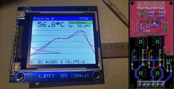
[randrews] did just that. He started out by purchasing a small memory LCD display from Adafruit. The screen he chose is low power as far as screens go, so it would be a good fit for this project. After testing the screen with a quick demo program, it was time to start designing the circuit board.
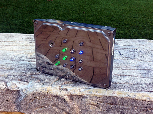
[randrews] used Eagle to design the circuit. He hand routed all of the traces to avoid any weird issues that the auto router can sometimes cause. He made an efficient use of the space on the board by mounting the screen over top of the ATMega chip and the other supporting components. The screen is designed to plug in and out of the socket, this way it can be removed to get to the chip. [randrews] needs to be able to reach the chip in order to reprogram it for different games.
Once the board design was finished, [randrews] used his Shapeoko CNC mill to cut it out of a copper clad board. He warns that you need to be careful doing this, since breathing fiberglass dust is detrimental to living a long and healthy life. Once the board was milled out, [randrews] used a small Dremel drill press to drill all of the holes.
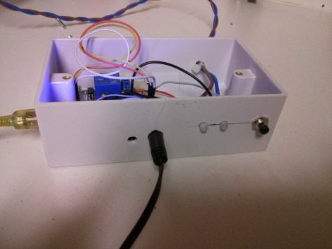
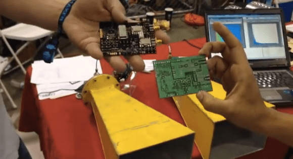
The final piece of the puzzle was to figure out the power situation. [randrews] designed a second smaller PCB for this. The power board holds two 3V coin cell batteries. The Arduino expects 5V, so [randrews] had to use a voltage regulator. This power board also contains the power switch for the whole system.
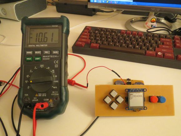
The power board was milled and populated. Then it was time to do some measurements. [randrews] measured the current draw and calculates that he should be able to get around 15 hours of play time using the two 3V coin cell batteries. Not bad considering the size.
[via Reddit]
Filed under: Arduino Hacks


 The very first fully operational radar Arduino shield

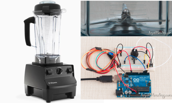 Some people really love their smoothies. We mean really, really, love smoothies and everything about making them, especially the blenders. [Adam] is a big fan of blenders, and wanted to verify that his Vitamix blenders ran as fast as the manufacturer claimed. So he built not one, but

 There are dozens, if not hundreds of examples around the Intertubes of an Arduino generating a VGA video output. The Arduino isn’t the fastest chip by far, and so far, all of these VGA generation techniques have peaked out at lower resolutions if you want to control individual pixels.[PK] has