As if we didn’t have enough to worry about in regards to the coming robot uprising, [Ali Aslam] of Potent Printables has recently wrapped up work on a 3D printed robot that can flatten itself down to the point it can fit under doors and other tight spaces. Based on research done at UC Berkeley, this robot is built entirely from printed parts and off the shelf hardware, so anyone can have their own little slice of Skynet.
On display at East Coast RepRap Festival
The key to the design are the folding “wings” which allow the robot to raise and lower itself on command. This not only helps it navigate tight spaces, but also gives it considerable all-terrain capability when it’s riding high. Rather than wheels or tracks, the design uses six rotors which look more like propellers than something you’d expect to find on a ground vehicle. These rotors work at the extreme angles necessary when the robot has lowered itself, and allow it to “step” over obstructions when they’re vertical.
For the electronics, things are about what you’d expect. An Arduino Pro Mini combined with tiny Pololu motor controllers is enough to get the bot rolling, and a Flysky FS-X6B receiver is onboard so the whole thing can be operated with a standard RC transmitter. The design could easily be adapted for WiFi or Bluetooth control if you’d rather not use RC gear for whatever reason.
Want to build your own? All of the STL files, as well as a complete Bill of Materials, are available on the Thingiverse page. [Ali] even has a series of videos on YouTube videos walking through the design and construction of the bot to help you along. Outside of the electronics, you’ll need a handful of screws and rods to complement the 50+ printed parts. Better start warming up the printer now.
Taking a vintage radio and cramming it full of modern, Internet-connected, guts has long been a staple of the hacking and making scene. While some might see it as a crime to take what’s arguably a legitimate piece of history and turn it into nothing more than a slipshod case for the Raspberry Pi, we have to admit there’s a certain appeal to the idea. Taking the beauty of classic design and pairing it with more modern capabilities is getting the best of both worlds.
But this project by [Nick Koumaris] is a somewhat unique take on the concept. Rather than sacrificing a real vintage piece of hardware to house the electronics, he’s designed a 3D printable case that looks like a classic 1936 AWA Radiolette. But what’s really interesting to us is that he then puts a basic FM radio inside of it.
That’s right, no Internet radio streaming or smartphone Bluetooth compatibility here. It’s just a regular FM radio, not entirely unlike the kind of hardware you’d expect to be inside of a classic radio. Of course, it’s much more modern, and [Nick] actually built it himself from a TEA5767 FM radio module and an Arduino Pro Mini.
While functionally it might not be terribly exciting, we do appreciate that he went through the trouble to make a vintage-looking user interface for the radio. While physical buttons would arguably have been more appropriate given the era, the art deco inspired font and graphics that show on the device’s Nokia 5110 LCD do look really slick.
After you’ve taken a moment to ponder the turn of phrase used in the title, take a look at this scratch-built robotic vacuum created by [theking3737]. The entire body of the vacuum was 3D printed, and all of the internal electronics are off-the-shelf modular components. We can’t say how well it stacks up against the commercial equivalents from iRobot and the like, but it doesn’t look like it would be too hard to build one yourself to find out.
The body of this rather concerned-looking robot was printed on a DMS DP5 printer, which is a neat trick as it only has a build platform of 200 mm x 200 mm. Once all the pieces were printed, a 3D pen was used to “weld” the sections together. The final result looks a bit rough, but should give a bond that’s just as strong as the printed parts themselves.
The robot has four sets of ultrasonic range finders to detect walls and obstacles, though probably not in the positions you would expect. The right side of the robot has two sets of sensors, while the left side only gets one. We aren’t sure the reasoning behind the asymmetrical layout, but presumably the machine prefers making right turns.
Control is provided by an Arduino Mega and the ever-reliable HC-05 Bluetooth module. A companion Android application was written which allows configuring the robot without having to plug into the Arduino every time you want to tweak a setting.
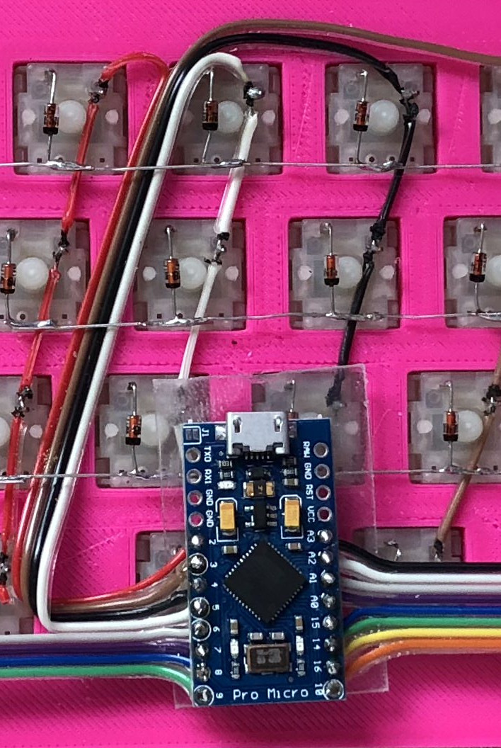
While the vast majority of us are content to plod along with the squishy chiclet keyboards on our laptops, or the cheapest USB membrane keyboard we could find on Amazon, there’s a special breed out there who demand something more. To them, nothing beats a good old-fashioned mechanical keyboard, where each key-press sounds like a footfall of Zeus himself. They are truly the “Chad” of the input device world.
But what if even the most high end of mechanical keyboards doesn’t quench your thirst for spring-loaded perfection? In that case, the only thing left to do is design and build your own. [Matthew Cordier] recently unveiled the custom mechanical keyboard he’s been working on, and to say it’s an elegant piece of engineering is something of an understatement. It may even better inside than it does on the outside.
The keyboard, which he is calling z.48, is based around the Arduino Pro Micro running a firmware generated on kbfirmware.com, and features some absolutely fantastic hand-wiring. No PCBs here, just a rainbow assortment of wire and the patience of a Buddhist monk. The particularly attentive reader may notice that [Matthew] used his soldering iron to melt away the insulation on his wires where they meet up with the keys, giving the final wiring job a very clean look.
Speaking of the keys, they are Gateron switches with DSA Hana caps. If none of those words mean anything to you, don’t worry. We’re through the Looking Glass and into the world of the keyboard aficionado now.
Finally, the case itself is printed on a CR-10 with a 0.3 mm nozzle and 0.2 mm layers giving it a very fine finish. At 70% infill, we imagine it’s got a good deal of heft as well. [Matthew] mentions that a production case and a PCB are in the cards for the future as he hopes to do a small commercial run of these boards. In the meantime we can all bask in the glory of what passes for a prototype in his world.
The first time I saw 3D modeling and 3D printing used practically was at a hack day event. We printed simple plastic struts to hold a couple of spring-loaded wires apart. Nothing revolutionary as far as parts go but it was the moment I realized the value of a printer.
Since then, I have used OpenSCAD because that is what I saw the first time but the intuitiveness of other programs led me to develop the OpenVectorKB which allowed the ubiquitous vectors in OpenSCAD to be changed at will while keeping the parametric qualities of the program, and even leveraging them.
All three values in a vector, X, Y, and Z, are modified by twisting encoder knobs. The device acts as a keyboard to
select the relevant value
replace it with an updated value
refresh the display
move the cursor back to the starting point
There is no software to install and it runs off a Teensy-LC so reprogramming it for other programs is possible in any program where rotary encoders may be useful. Additional modes include a mouse, arrow keys, Audacity editing controls, and VLC time searching.
[Editor’s note: This is a Hackaday writer’s hack, hence the “I” in place of the usual “we”. We all love custom peripherals though, and a good number of us love OpenSCAD, so you could probably read it either way, but we don’t want to take credit for [Brian]’s work.]
If you go to the University of South Florida, you can take the “Makecourse.” The 15-week program promises to teach CAD software, 3D printing, Arduino-based control systems, and C++. Don’t go to the University of South Florida? No worries. Professor [Rudy Schlaf] and [Eric Tridas] have made the entire course available online. You can see several videos below, but there are many more. The student project videos are great, too, like [Catlin Ryan’s] phase of the moon project (see below) or [Dustin Germain’s] rover (seen above).
In addition to a lesson plan and projects, there’s a complete set of videos (you can see a few below). If you are a regular Hackaday reader, you probably won’t care much about the basic Arduino stuff and the basic electronics–although a good review never hurts anyone. However, the more advanced topics about interrupts, SDCards, pin change interrupts might be just the thing. If you ever wanted to learn Autodesk Inventor, there are videos for that, too.
If you don’t need any of the instruction offered, this would still make a great program to offer at a local hacker space or anywhere else where you want to teach build to build. You can see from the variety of student projects that it is well-balanced and lets students focus on areas where they are most interested.
So much educational material is online now that it is hard to find time to see even a fraction of it. We love EdX, for example, but who has the time to take even a fraction of the classes offered? We always love seeing student projects–they give us ideas. [Bruce Land’s] classes, in particular, are always inspirational.
Keeping track of your 3D-printer filament use can be both eye-opening and depressing. Knowing exactly how much material goes into a project can help you make build-versus-buy decisions, but it can also prove gut-wrenching when you see how much you just spent on that failed print. Stock filament counters aren’t always very accurate, but you can roll your own filament counter from an old mouse.
[Bin Sun]’s build is based around an old ball-type PS/2 mouse, the kind with the nice optical encoders. Mice of this vintage are getting harder to come by these days, but chances are you’ve got one lying around in a junk bin or can scrounge one up from a thrift store. Stripped down to its guts and held in place by a 3D-printed bracket, the roller that used to sense ball rotation bears on the filament on its way to the extruder. An Arduino keeps track of the pulses and totalizes the amount of filament used; the counter handily subtracts from the totals when the filament is retracted.
Simple, useful, and cheap — the very definition of a hack. And even if you don’t have a 3D-printer to keep track of, harvesting encoders from old mice is a nice trick to file away for a rainy day. Or you might prefer to just build your own encoders for your next project.
With All Hallow’s Eve looming close, makers have the potential to create some amazing costumes we’ll remember for the rest of the year. If you’re a fan of the hugely addict-*cough* popular game Minecraft, perhaps you’ve considered cosplaying as your favorite character skin, but lacked the appropriate props. [Graham Kitteridge] and his friends have decided to pay homage to the game by making their own light-up Minecraft swords.
These swords use 3D-printed and laser-cut parts, designed so as to hide the electronics for the lights and range finder in the hilt. Range finder? Oh, yes, the sword uses an Arduino Uno-based board to support NewPixels LEDs and a 433Mhz radio transmitter and receiver for ranged detection of other nearby swords that — when they are detected — will trigger the sword to glow. Kind of like the sword Sting, but for friendlies.
All of the files for the parts are available on the project’s Thingverse page and the board setup can be purchased here. If you want to have some fun controlling the real world from inside Minecraft, check out how this fan uses it to turn on lamps in their home.
Adjust the phase current, crank up the microstepping, and forget about it — that’s what most people want out of a stepper motor driver IC. Although they power most of our CNC machines and 3D printers, as monolithic solutions to “make it spin”, we don’t often pay much attention to them.
In this article, I’ll be looking at the Trinamic TMC2130 stepper motor driver, one that comes with more bells and whistles than you might ever need. On the one hand, this driver can be configured through its SPI interface to suit virtually any application that employs a stepper motor. On the other hand, you can also write directly to the coil current registers and expand the scope of applicability far beyond motors.
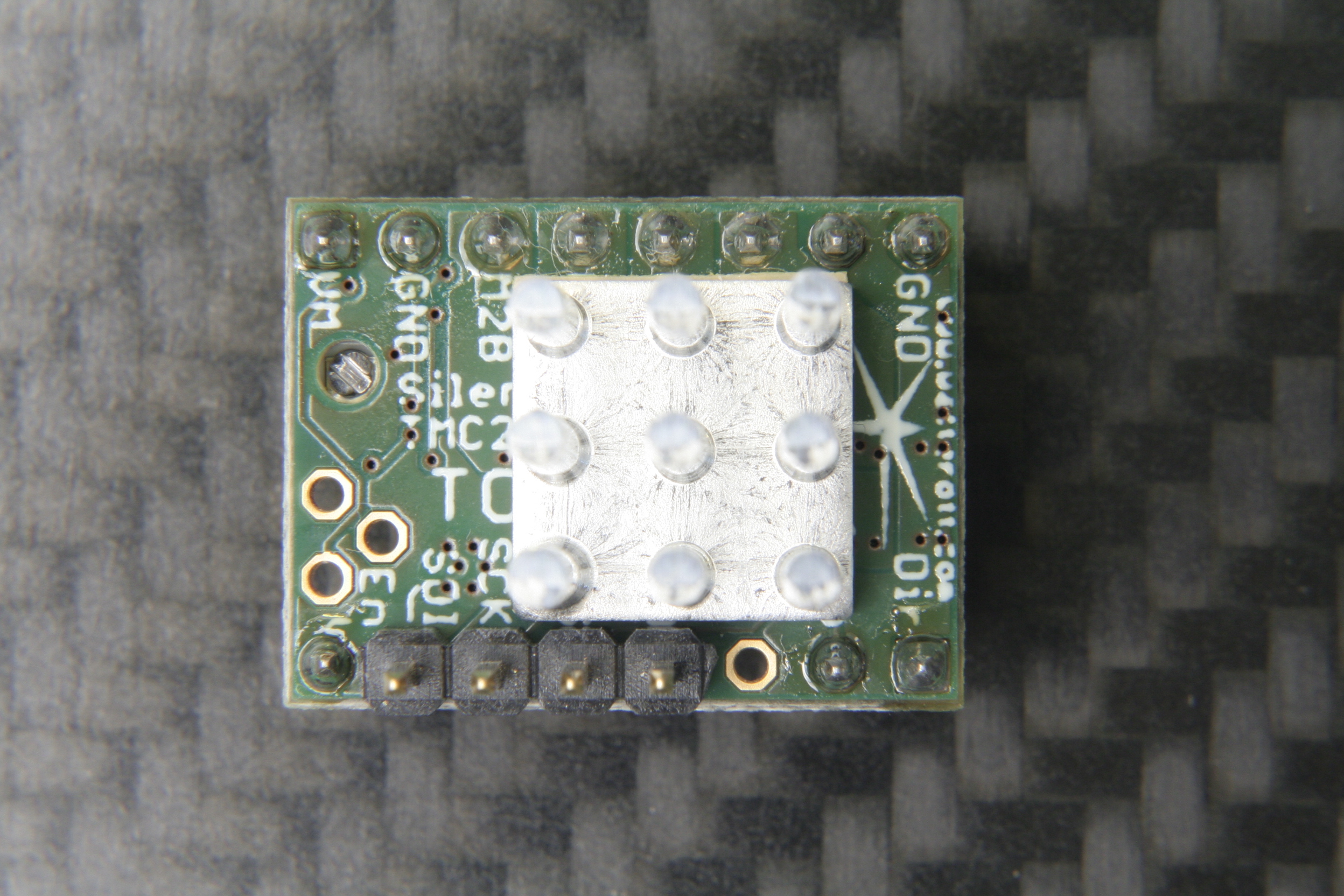
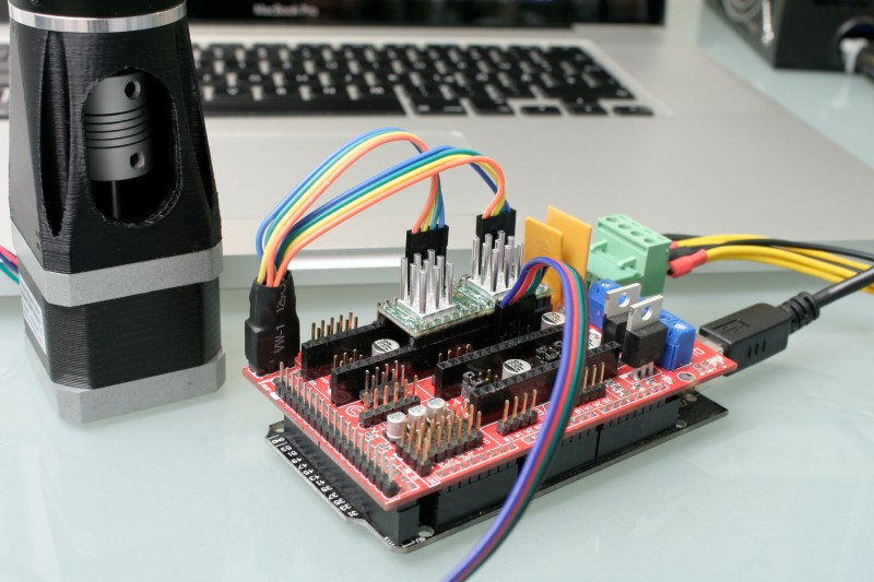
The TMC2130 SilentStepStick’s top side with SPI headers and heatsink.
Last month, we took a closer look at microstepping on common stepper driver ICs, but left out the ones that we actually want to use: the smart ones. Trinamic provides some of the smartest stepper motor drivers on the market, and since the German hacker store Watterott released their SilentStepStick breakout boards for the TMC2100 and TMC2130, they are also setting a new standard for DIY 3D printers, mills and pick-and-place robots. I recently acquired a set of both of them for my Prusa i3 3D printer, and the TMC2130 with its SPI configuration interface really caught my attention.
The TMC2130 SilentStepStick should not be confused with the — far more popular — TMC2100 variant. As the name suggests, it comes as a StepStick-compatible breakout board, and just like it’s famous sibling, features a Trinamic IC on the bottom side of the little PCB. Several vias and copper spills conduct heat away from the IC’s center pad, allowing a heatsink on the top side to effectively cool the driver.
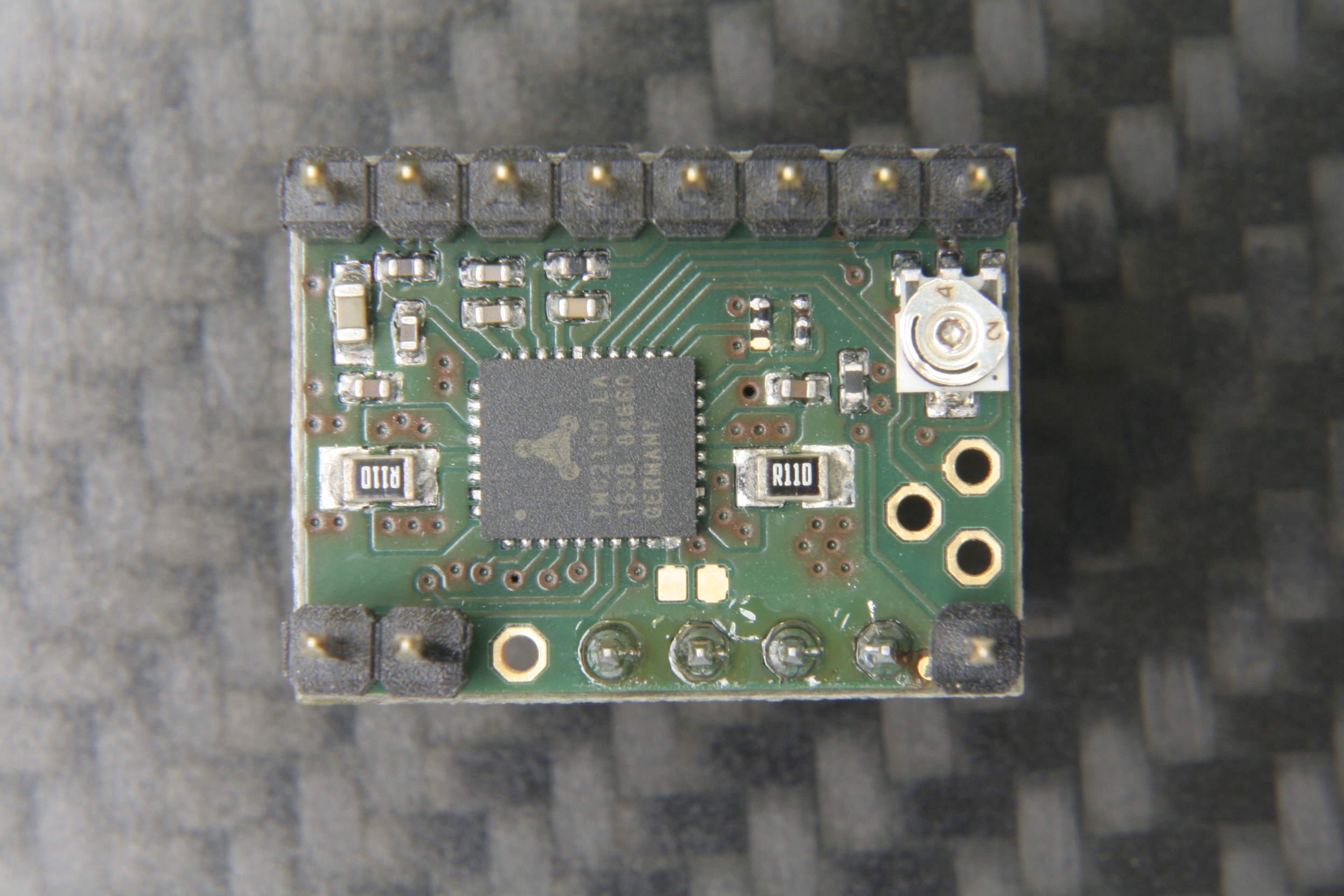
The bottom side with the stand-alone mode solder blob jumper next to the IC.
However, unlike the TMC2100, this one won’t let your motors spin right away. You’ve got two options: Hard-wire it in stand-alone mode, which practically turns it into a TMC2100, or hook up to its SPI-interface and dial in if you want your stepper motor shaken or stirred. In fact, plentiful configuration registers make the TMC2130 an extremely hackable chip, so I’m not even thinking about bridging that solder jumper on the SilentStepStick’s bottom side that activates the stand-alone mode.
First Steps
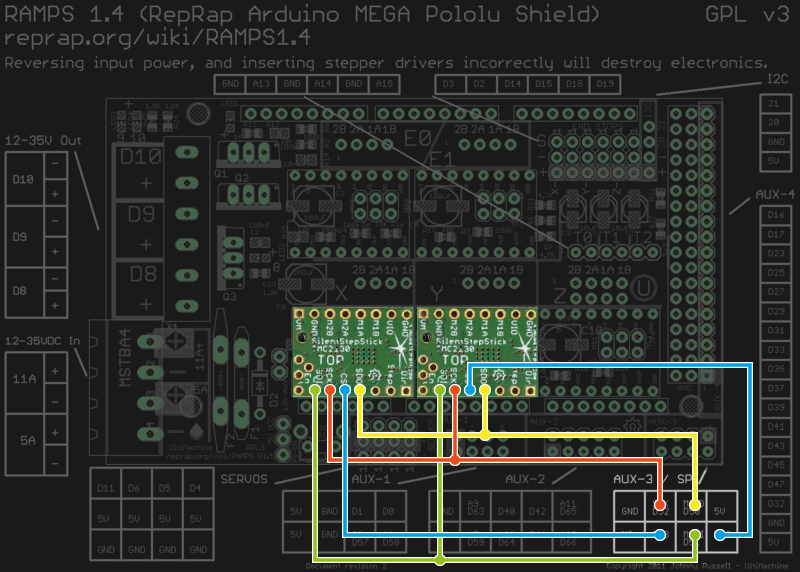
Wiring the TMC2130 to a classic RAMPS 1.4.
As said, before the driver does anything, it wants to be configured, and it’s worth mentioning that all configuration registers are naturally volatile, so if I want to use them in my 3D printer, I need to configure them as part of the printers startup routine.
The RAMPS 1.4 on my 3D printer breaks out the hardware SPI interface of the underlying Arduino through its AUX3 pin header, along with two additional digital pins (D53 and D49), which I used for the cable select signals. After crimping a cable to connect two TMC2130’s to the AUX3 header, I could start digging into the software part.
Watterott provides an example sketch, which writes a basic configuration to the driver’s registers and spins an attached stepper motor. Great stuff, but the datasheet describes 23 configuration registers waiting to be finely tuned, and 8 more to read diagnosis and status data from. So, I wrote a little Arduino library that would make the numerous configuration parameters available in a more practical way. From there, I could just include my library into the Marlin-RC7 3D printer firmware I’m using. Luckily, the current Marlin release candidate already features support for TMC26X drivers, so I could reuse some of its code to put together a Marlin fork that includes 59 of the TMC2130’s parameters in its define-based configuration files. And then, I could take the little buddies out for a spin.
First steps on a RAMPS 1.4 on a somewhat-uino (sorry Massimo). The testing-contraption to the left is a NEMA 17 stepper motor attached to an encoder.
Taking Them For A Spin
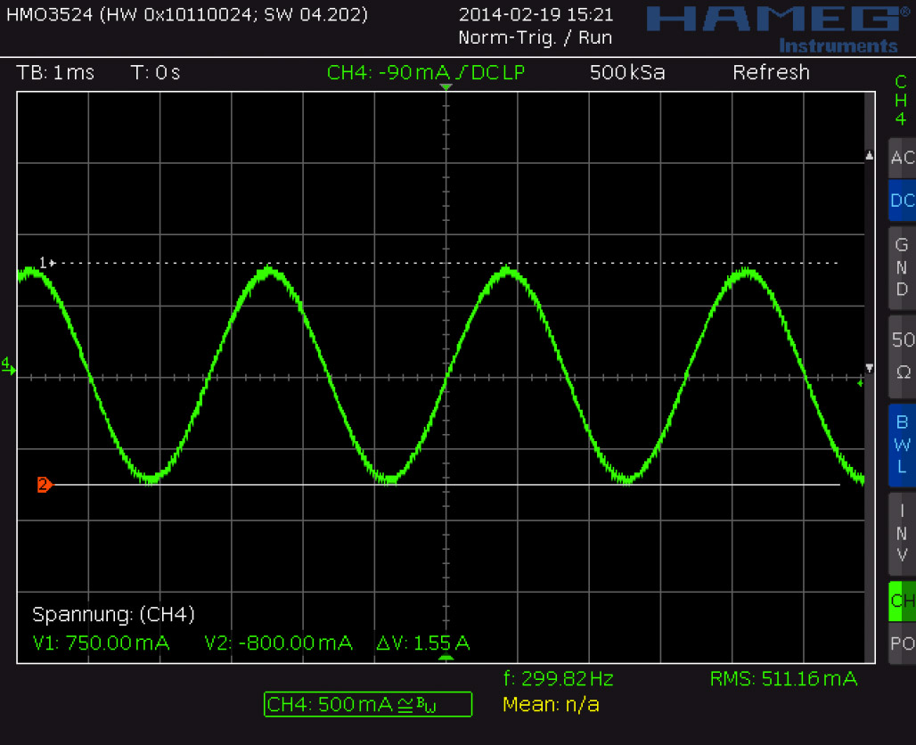
With the hardware set up and the software working as supposed, I ran a few sanity tests: toggling parameters on and off and checking how the driver’s behavior changes during printing. Since the TMC2130 let’s you tune almost everything it’s doing, that’s a good first step that helps to eliminate some variables and picking others that are worth a deeper look. Most of the settings can be changed on the fly and mid-print, however, not all parameters can actually be safely changed while the motors are running.
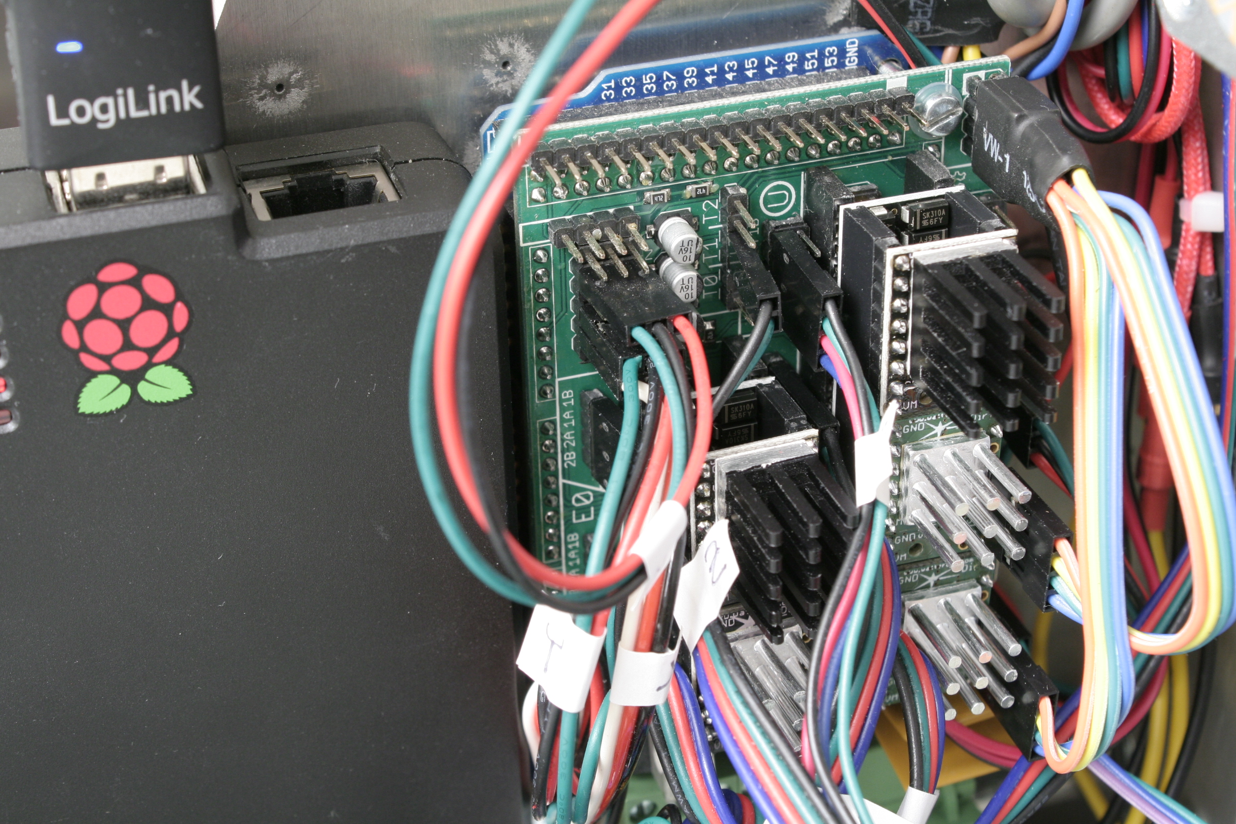
The TMC’s in service. I’m using the SPI-configurable TMC2130’s (silver heatsink) for the X- and Y- axis. The Z-axis and the extruder feature the TMC2100 (black heatsink). All of them are sitting on additional free-runner diode protection shields.An excerpt of Trinamic’s thorough quick start guide.
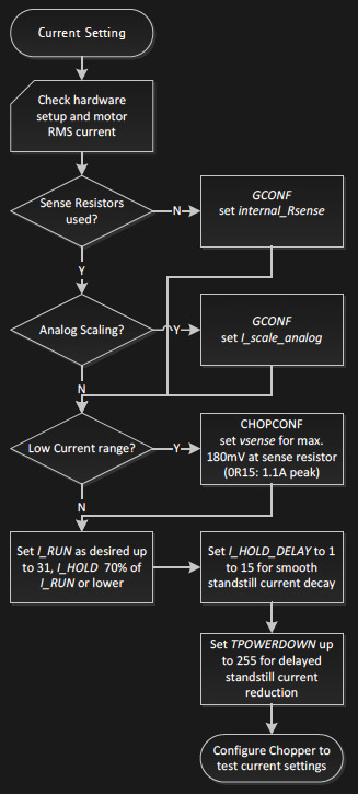
To actually tune the drivers for a certain application, Trinamic provides a quick start guide in the datasheet, as well as detailed information on each parameter, and on how they interact. Basically, the first step is adjusting the RMS coil current by using the onboard potentiometer on the SilentStepSticks. Then, we need to chose the analog input pin as a current scaling reference to actually make use of the potentiometer. The mentioned library lets me do this through a simple method:
myStepper.set_I_scale_analog(1); // 0: internal, 1: AIN
The running and holding current are the first real parameter that should be tuned, with the running current typically at the desired maximum current, and the holding current at 70% of this value. The delay between a stillstand and the transition from running current to holding current can be adjusted between 0 and 4 seconds, and for now, I set it to 4 seconds, practically disabling the current reduction while the 3D printer is running. The three values share one write-only register, so the corresponding method call looks like this:
and sets the running current to 100% (≙ 31), the holding current to about 70% of this value (≙ 22), and the delay between the two to 4 seconds (≙ 5).
I want torque, so I can leave stealthChop disabled. The datasheet suggests some starting values for configuring the chopper’s off time and the comparator’s blank time settings, but since it’s a key tradeoff between switching noise and torque, it makes sense to iterate through other values as well. The library methods for the two values look like this:
And finally, I need to pick a microstepping resolution and choose if I want to make use of the 256 microstep interpolation feature, covered later in this article:
I have yet to walk through the entire tuning procedure, which includes monitoring the coil current on the scope and eliminating distortions in the zero crossing, but I’m getting a clue of the driver’s potential.
Juice
It’s maximum continuous RMS current of about 1.2 A per coil (at least in the QFN package on the SilentStepSticks) lets it look like a low-current driver, inferior to the common A4988 and DRV8825. In practice, it outperforms both of them by making intelligent use of a 2.5 A peak current margin. This gives it more than enough torque for 3D printing. I wouldn’t recommend pushing them over 0.9 A RMS though since the IC will momentarily pull more current if it needs more. For SilentStepStick users, that’s a Vref of 0.88 V. Through the SPI-interface, you can choose how much current you want to send through the motor coils when it’s spinning, and when it’s idling. You can choose after how many seconds it will start to decrease the current to a lower holding current when the motor is in standstill, and then to an even lower idling current. And, of course, you can also set it to squeeze out the maximum juice for everything.
Shifting The Gears
Where it starts getting interesting are settings like the high-velocity mode. Above a configurable velocity threshold, the driver offers you to automatically switch the chopper to a faster decay time to squeeze out some extra speed. You can also literally shift the gears by letting the driver internally switch from microstepping to full-step mode once it’s up to speed.
Microstepping
Choosing a finer microstepping resolution smoothens the stepper’s movement, reduces vibrations and sometimes even increases the positioning accuracy. However, it also multiplies the load on the microcontroller, which has to churn out 16, 32 or 256 times more step pulses per second. The TMC2130 lets you pick an input resolution between 1 and 256 microsteps per full-step, and then gives you the option of interpolating the output resolution to 256 microsteps. This allows for smooth operation even on increasingly retro 8-bit AVR motion controllers, which cannot deliver high step frequencies. Also, by configuring the TMC2130’s interface to double-edge step pulses, you can at least double the step frequency at almost no cost. Given that the modern IC still features the classic step/direction interface and even an enable pin, those few additional features actually make it a sweet drop-in upgrade for less-recent CNC and 3D printer electronics.
Noise Reduction
The TMC2130’s datasheet promises undistorted output with stealthChop.
Just like the TMC2100, the TMC2130 features two efficient and silent drive modes: spreadCycle, and stealthChop. The former delivers high torque at relatively low noise emissions, the latter one is almost inaudible but delivers a dramatically reduced torque. The flexible IC also allows you to tweak the chopper yourself to find the right balance between torque, noise, and efficiency for your application. One of the more noteworthy options in this regard is the possibility of randomizing the chopper’s off time. Since most of the audible noise is released due to dubstep the chopper busily switching the stepper motor’s coils, this option spreads the noise over a wider frequency range to subjectively silence the stepper motor.
Stall Detection
The TMC2130 notices when the motor is stalled and losing steps by measuring the motor’s back EMF. Along the way, it counts missed steps, allowing the controller to compensate for otherwise irreversible step-loss. It’s also a great way to react to obstacles rather than running into them full-force and, of course, the feature can be used as an axis endstop. Trinamic calls this feature StallGuard, and just like anything else in this motor driver, it’s highly configurable.
Direct Mode
Instead of letting the motor driver handle everything for you, you can also choose the direct mode. This mode practically turns the driver into a two-channel, bipolar constant-current source with SPI interface. You can still use it as a motor driver, but the possibilities reach far beyond that. It’s worth mentioning that the datasheet might be a bit confusing here, and the corresponding XDIRECT register actually accepts two signed 9 bit integers (not 8 bit) for each coil and operates as expected within a numeric range of, naturally, ± 254 (not ± 255) to vary the current between ± Imax/RMS..
The Takeaway
About half a year after the release of Watterott’s breakout board, the potential of smarter stepper motor drivers piqued the curiosity of the 3D printing community, but not much has happened in terms of implementation. Admittedly, it takes some effort to get them running. If you’re still busy dialing in the temperature on your 3D printer, you surely don’t want to add a few dozen new variables, but if you’re keen on getting the best out of it, the TMC2130 has a lot to offer: low-noise printing, high-speed printing, print interrupt on failure and recovery from lost steps. Because the driver IC is so hackable, it’s clearly intended to be tuned in to accommodate specific applications. Throwing it on a general purpose test bench probably won’t yield meaningful, general purpose results.
I hope you enjoyed taking a look at a smarter-than-usual stepper motor driver, as one of the new frontiers of DIY 3D printing, and as an interesting component with many other applications. If you’re thinking about experimenting with this IC or breakout board in your 3D printer, feel free to try my Marlin fork to get started. If you’re building something entirely different, the underlying Arduino library will help you out. Who else is using this part? I’ll be glad to hear about your ideas, applications, and experiences in the comments!
A personal bartender is hard to come by these days. What has the world come to when a maker has to build their own? [Pierre Charlier] can lend you a helping hand vis-à-vis with HardWino, an open-source cocktail maker.
The auto-bar is housed on a six-slot, rotating beverage holder, controlled by an Arduino Mega and accepts drink orders via a TFT screen. Stepper motors and L298 driver boards are supported on 3D printed parts and powered by a standard 12V DC jack. Assembling HardWino is a little involved, so [Charlier] has provided a thorough step-by-step process in the video after the break.
[Charlier] has also kindly included his Arduino code to further facilitate your happy hour. The best part? This is isn’t even the final product; and yet — this functional prototype can already turn the tables on a long day. Whatever your beverage of choice, make sure it stays as hot or cool as you want with the help of this handy coaster.


