Posts with «xbee» label

Arduino based Quadrotor on a PCB

There are many Quadrotor Projects out there. But, they require a hobbyist to deal with the Frame Designing (Mechanical), a bit of Microcontroller knowledge as well as dealing with the Motor Control (Power Electronics). You may purchase a commercial Radio and a readymade Kit for flying. But, to Do-It-Yourself, is an achievement in itself.

Here is a picture of a Quadrotor designed by Shane Colton using Arduino Pro mini as its flying brain. Shane is a Ph.D Student at Massachusetts Institute of Technology. On being asked about the Project, he replied:

I heard about Arduino some time in 2007/2008 and have used it for a few projects since then. I built the quadrotor for fun / hobby (not related to research). I wanted to build my own (quadrotor) from scratch because I could integrate all the parts onto a single circuit board, and because I like designing the control system myself.

When he says he build the quad from scratch, he literally did it. Neither did he use any commercially available Radio Control, nor did he use any Electronic Speed Controllers (ESCs). Instead he went for creating his own Brushless DC Motor Controller, that too, on the same PCB which acts as the Quadrotor’s Frame.

He spent a lot of time researching about propellor balancing as well as vibrations in the PCB. Here is a video:

Now, that is called a hobby. In a detailed Instructable, he shows how you too can build a Quadrotor on a PCB. He has a project blog at http://scolton.blogspot.com with documentation on most of his projects.

Enjoy the ride:

Arduino Blog 06 Jun 07:47

Arduino gets 3G connectivity

Libelium, with its open source hardware division of Cooking Hacks has come out with a new 3G module for arduino.

The new 3G shield for Arduino enables connectivity to high speed WCDMA and HSPA cellular networks allowing transfers up to 7.2Mbps (20 times faster than with GPRS technology). The module also counts with an internal GPS that enables the location of any Arduino both outdoors and indoors, combining standard positioning data from satellites with mobile cell triangulation in the assisted mobile mode (A-GPS).

The new Arduino 3G module also includes a small camera for video recording in high resolution and a complete audio interface that enables Arduino to run with all the functionalities of a smartphone device.

And just to remind our readers about cooking hacks? They were the people who created the XBee shield for arduino.

Further information regarding this new 3G/GPRS module can be found here.

Via:[EMSnow, cooking-hacks, memristor]

Arduino Blog 29 May 19:27
3g  arduino  xbee  

DIY Radio Control

Going to buy a new Wireless Controller for your next Robotics project. Why buy a new one when you can Do-It-Yourself? All you need is an Arduino, an old Joystick with a Gameport (15-pin connector) and a pair of Series 1 xBee Modules.

The explanation of the xBee Configuration and the xBee Packet Description is very well done at the blog.

Transmitter: Joystick + xBee [No additional hardware needed]
Receiver: xBee + Arduino + [your amazing Robot, Car or a Plane!]


WineShade: Hipster Stack-Powered Voting Gizmo for O’Reilly’s Strata Conference

I was asked to make something for the O’Reilly Strata Conference, which was held in Santa Clara at the end of February 2012. We needed some devices to capture vote from attendees who participated in Coco Krumme‘s Data Crush: Where Wine and Data Meet:

This new event at Strata will host wine tastings for participants, whose feedback data will be compiled and analyzed to extrapolate behavioral trends and factors influencing their responses.

I decided the best way to accomplish this was to shovel a bunch of new technologies into the project: MakerBot, XBee, Arduino, Node.js. I believe it was Alasdair Allan who dubbed this the hipster stack. I believe it was Alex Howard who dubbed it the WineShade. But between the wine and solder fumes, my memory is suspect!

MakerBot
If I’m going to make something physical, I knew my MakerBot Thing-O-Matic could make my life easier. At first, I thought I’d use the MakerBot to print out something to hold buttons and indicators in place, but I decided to go with some foam core for this. I had decided to use lampshades as the chassis for each station, and I needed something to cap it off. So I made a little tower to go on top of each one. I eventually went with something smaller than what you see here.

Arduino Mega
I knew I’d need a lot of I/O, since each station would have three bargraphs and three buttons (though we ended up using only two each). I didn’t want to put too many components into this since I’d need to build them, so I decided to drive the bargraphs directly from the Arduino pins. To minimize the number of transistors, I decided to take advantage of persistence of vision, and multiplex the bargraph. I wrote a small library for the Adafruit LED bar graphs to do this, and posted it to GitHub. I’m just using one color, but the library could easily be extended to handle both of the bar graph’s colors.
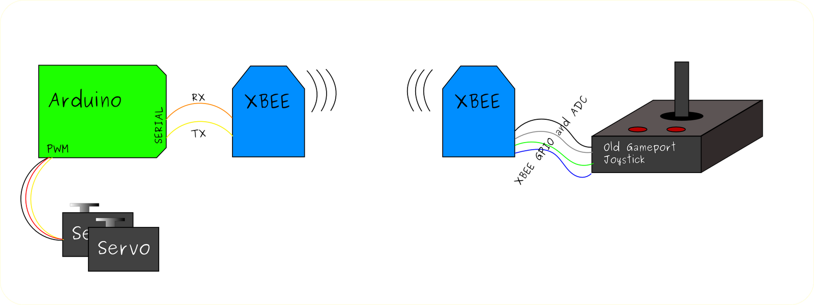
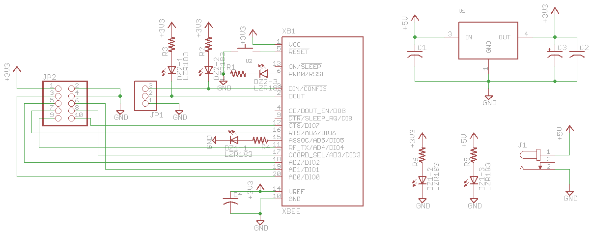
Digi’s XBee
These voting stations would be spread out all over the place, and needed a way to talk to a central server. I’ve had a lot of experience with Digi’s XBee modules, and I’ve always wanted to use the XBee Internet Gateway (XIG) in a project. XIG lives on a Digi ConnectPort X, and acts as a gateway between the XBee network and web servers (XIG can also talk to the IDigi cloud). I reached out to Rob Faludi, author of Building Wireless Sensor Networks, and he arranged to loan me a ConnectPort X2 Industrial and four XBee Pro modules. Thanks, Rob (and Digi)! I liked XIG so much that I bought a ConnectPort X2 Commercial (less RAM than the Industrial, but it works well for me).

Node.js
If I’m going to have the XBees talking to the network, they better have a server to talk to. I usually reach for PHP or Perl for this sort of thing, but I decided I’d heard enough about Node.js (Beagle Bone‘s adoption of it got me really interested in it) that I better look into it. It worked great. It would have taken me longer to write this in PHP (or any of my usual languages) than it did for me to learn Node.js and implement it. Once I got my head around the asynchronous insanity, I could add whatever feature struck my fancy in a matter of minutes (OK, so some features needed more minutes than others).

The trickiest part of building each unit was connecting the Arduino Mega to all the pins on the buttons and LED displays. I decided to take an Adafruit perma-proto breadboard, solder some long male pins to it, and shape them so they’d plug into the double row of headers on the Arduino Mega. It was a kind of makeshift Arduino Mega tail shield, but it works. I threaded each strand of ribbon cable into a breadboard hole and up before soldering it down, which gave me quite a bit of strain relief.

I’ve got some documentation in process in the form of a GitHub repository that includes the Arduino code. It’s a pretty simple system: when the Arduino boots up, it sends a URL over the serial port that the XBee’s connected to (you’ll want to modify the server string in the Arduino source), and XIG relays this to the server, and sends the response back to the Arduino over the XBee network. The server is a Node.js server that handles the requests from the Arduino: press a button, and a vote is registered. At each bootup (and after each button press), the Arduino gets the current vote tally from the Node server. That way, the Arduino doesn’t have to store any state at all! There’s also a primitive UI (/dash on the server) that lets you view the votes and manipulate them or reset them if needed. The index.js file lists all the handlers, and the corresponding handler code is in requestHandlers.js.

Flick set: WineShade for Strata
GitHub repo: bjepson/WineShade


MAKE » Arduino 10 Apr 23:30

Micro Magician robot controller - I can finally tick the project complete box!

I started designing this controller in December 2011. After 4 months and 2 previous revisions it will finally be shipping out April 2012. I think this is DAGU's best Arduino compatible robot controller yet!

Designed for small robots using small batteries, the Micro Magician is a 3.3V controller running at 8MHz.
Working from 3.6V to 9V means this constroller can run from a single LiPo cell or 3x NiMh batteries.
Reverse polarity protection means no blue smoke if you get your power wires crossed (reverse polarity diode rated at 3A).

read more

Testing the XBee on Wise Clock 4

To test the XBee on Wise Clock 4 I used the sketch below (upload it to the board; display is not required).

int nCount = 0;
void setup()
{
  Serial.begin(9600);
  Serial1.begin(9600);
  Serial.println("WC4 XBee ready for comm..."); 
}


void loop()
{
  // read from port 1, report characters on port 0:
  while (Serial1.available())
  {
    char inChar = Serial1.read();
    Serial.print(inChar); 
  }
  Serial1.print("WC4 XBee transmit ");
  Serial1.print(nCount++);
  Serial1.print(", ");
  Serial1.println(millis());
  delay(3000);
}

Notice the use of Serial1 instance to talk to the XBee, since this is connected to the second hardware serial port of the ATmega644P (D10/D11, pins 16/17). Had Sanguino offered no support for the second USART, we could have used NewSoftwareSerial library.

The second XBee is linked directly to a terminal (e.g. HyperTerminal in Windows, or Terminal panel in the X-CTU application from Digi). I personally used the XBee Adapter from Adafruit, connected through the FTDI cable to the PC as shown here.

Once this XBee test passed, you can adapt the Wise Clock 4 software to display any message sent to it from a second XBee. A simple hack is to add to the function fetchMessage() in file WiseClock4.cpp, as shown below:

void WiseClock4::fetchMessage()
{
  // new code for XBee............
  // read from XBee into the "personalized message" buffer;
  char* Ptr1 = &personalMsg[0];
  if (Serial1.available())
  {
    while (Serial1.available())
    {
      *Ptr1++ = Serial1.read();
    }
    *Ptr1 = 0;
  }

  // existing code................
  strcpy(msgLine, "      ");

Now, instead of the personalized message (read from file message.txt on the SD card) you will get whatever is sent from the terminal application (second XBee).

Don't forget to add this line in function setup (file WiseClock4.pde):

  Serial1.begin(9600);


Wise Clock 4

The new Wise Clock 4 board has two main improvements over Wise Clock 3:
  • support for the XBee family of wireless RF modules (XBee, XBee Pro, XBee Wi-Fi, and the similar foot-printed Roving Networks WiFly RN-XV);
  • ability to easily connect a second display; this is achieved by moving the power connector on the "right" side, plus bringing the extension display connector closer to the bottom of the board.


Wise Clock 4 is "almost" compatible with Wise Clock 3. To run the existing sketch on Wise Clock 4, two changes are required:
  • Plus button is now on D3 (D2 is now designated for interrupts from RTC);
  • D15 is now connected to the CS line of the display, replacing D11, which is now used for communication with the Xbee module.


As can be noticed from the photos, a few more components are in SMD package (necessary to keep the size of the board to a minimum, to fit in the back of the 3216 display):

  • the level shifting buffer 74HC125;
  • three optional LEDs: 2 for the XBee communication lines, one for power;
  • the 3V3 voltage regulator MIC5219, capable of providing 500mA.


Updated Nov 26, 2011
The schematic, pictured below, can be downloaded from here (Eagle file).


The board layout, shown below, can be downloaded from here.


Spreadsheet: "Date Added" Column, More Boards

So many people have asked for a column on the Arduino-compatible board spreadsheet showing the date when each board was added, so I put that on the spreadsheet this week. I had to sift through the revisions, but it wasn't too much of a pain.

Also new to the spreadsheet:
  • Six boards by the Indian company Bhasha, all through-hole except for the FTDI USB chips, mostly simple designs but it's clear from the traces that the boards were reworked slightly. Interesting to see the "Severino" Single Sided Serial V3 design offered for sale, something I haven't seen elsewhere.
  • Zigduino by Logos Electromechanical is offering their first run of IEEE 802.15.4 radio-equipped boards for $70. I've been looking forward to these boards coming out, but the price seems high given that you could buy an Arduino FIO for $25 and an XBee module for $19, so $44 total, or a Freakduino Chibi for $33. I hope the high price is only for this first run and that it is lower when Logos goes into full scale production, but I also wonder if it's as easy to use as the widely available XBee modules for which there are many example sketches available. It does have XBee "Pro" capabilities though, and I'm not familiar enough with 802.15.4 to really compare it to other offerings. I look forward to more complete documentation on its specs along with full design files since it's unclear what its equipment and capabilities are.

n/a