Posts with «uno» label

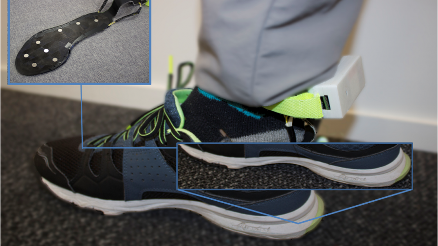
GymSoles ensure correct form and posture during your workout

While you can get a very good workout on your own, it’s ideal if you have someone else watching over your form. This, of course, isn’t always practical, so researchers at the University of Auckland’s Augmented Human Lab have prototyped a wearable system called GymSoles to help. 

GymSoles consist of a pressure-sensitive insole that is used to determine a foot’s center of pressure, and thus infer whether or not the participant is keeping the weights in the proper position relative to his or her body—perfect for exercises like squats and deadlifts. 

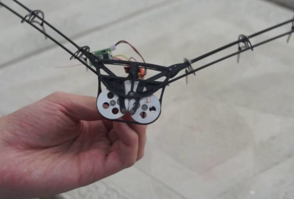
Feedback is provided visually as well as through tactile feedback via eight vibrating motors, allowing participants to modify technique without having to focus on a screen. A computer is used to control the device using an Arduino Uno with motor drivers and an I2C multiplexer.

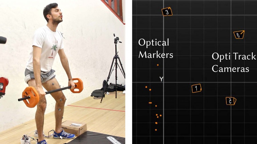
The correct execution of exercises, such as squats and dead-lifts, is essential to prevent various bodily injuries. Existing solutions either rely on expensive motion tracking or multiple Inertial Measurement Units (IMU) systems require an extensive set-up and individual calibration. This paper introduces a proof of concept, GymSoles, an insole prototype that provides feedback on the Centre of Pressure (CoP) at the feet to assist users with maintaining the correct body posture, while performing squats and dead-lifts. GymSoles was evaluated with 13 users in three conditions: 1) no feedback, 2) vibrotactile feedback, and 3) visual feedback. It has shown that solely providing feedback on the current CoP, results in a significantly improved body posture.

This compass reads the correct heading even when tilted

Consider an analog or even digital compass. While you can reasonably expect either to point towards magnetic north when held flat, when you add tilt and/or roll to the equation, things get a bit wonky. That is unless you’re maker “lingib,” who was able to construct a magical compass using an Arduino Uno and an MPU-9250 IMU unit, with an accelerometer/gyro in the same package.

As seen in the video below, when the compass unit is set at an angle, the heading output varies significantly—as much as 100 degrees according to the project write-up. When stabilization is turned on, however, the gyro/accelerometer is used to compensate for magnetometer heading variations—reducing output errors to just a few degrees.

This Instructable explains how to make a tilt compensated compass using an Arduino Uno R3, an LCD display, and an IvenSense MPU-9250 multi-chip-module that contains an MPU-6050 accelerometer / gyro and an AK8963 magnetometer within the same package.

The LCD simultaneously displays the heading, (P)itch, and (R)oll.

The heading accuracy is within 2 degrees depending on how well the compass has been calibrated.

Without tilt compensation the compass headings vary significantly … sometimes by as much as 100 degrees.

When stabilised, the tilted compass headings only vary by one or two degrees … the improvement is amazing.

The tilt stabilization may be disabled by placing a jumper wire between Arduino pins A0 and GND.

Arduino Blog 15 May 14:12

Modular CNC machine made with Arduino

Arduino boards running GRBL software have long been used for CNC machine control, but usually you need to choose between having a router or laser cutter. This project, however, is specifically designed to accommodate both with a modular carriage system.

Build-wise, it’s a fairly standard XYZ gantry CNC — with a frame made out of V-slot aluminum extrusions from OpenBuilds cut to length by a circular saw. The X and Y axes are controlled via NEMA 17 stepper motor and belt drive assemblies, while height adjustment is accomplished with a NEMA 23 motor and screw drive.

The electronics are all hidden away in a separate enclosure, including the Arduino Uno/CNC shield that serves as the brains of the operation and a cooling fan to keep the temperature inside in check. 

If you’ve been considering doing this type of build, this looks like a great place to start, and you can see a demos of it in laser and spindle modes in the videos below.

Clean your whiteboard automatically with Wipy

If you have to do a lot of drawing on a whiteboard, you also have to clean it. Why not have a robot do this instead? That’s the idea behind Wipy, an Arduino Uno-based robot that uses magnets to stick it to the board, plus grippy wheels and motors to power it across your scribbles.

Wipy employs an array of IR sensors that enable it to act as a line follower, along with a time-of-flight (ToF) sensor to detect your hand on the board. While one might assume this sensing arrangement would prevent it from erasing your work-in-progress, it annoyingly allows it to start erasing immediately when you start drawing on the board. At least it has a cute LED face!

Did you ever get tired of cleaning the whiteboard? Have you ever wondered how much your life would improve if a robot could do this for you? You now have the chance to make this a reality with Wipy: the overly motivated whiteboard cleaner. Wipy will properly clean your embarrassingly bad drawings, and it will even do it with a cute smile. You don’t even need to activate it! It will just clean the board when you least expect it… Uhhh…*cough cough*…we, of course, mean: when you need it most!

– Our future friend will be able to stick to the board using magnets and is able to move through space using grippy wheels.

– It will be able to follow a line and erase it using a line-following sensor and a sponge.

– Wipy has the ability to measure the distance to your hand using a time-of-flight sensor.

– We will give Wipy a cute personality using a small OLED screen.

Automated plant tending with Arduino

Do you like plants, but not so much the tending to and watering them? If that sounds like you, then you might be interested in your own CNC growing machine. The system—created by 15-year-old maker “daily3dprinting”—is controlled by an Arduino Uno, and uses a single stepper motor to pull a watering head into position based on hygrometer readings.

A relay is used to turn the grow light on at 6am and off at 8pm, and another to activate the unit’s water pump. A third relay is employed to power off the L298N stepper driver when not needed. 

The project took home second place in the math and engineering category at daily3dprinting’s high school science fair, and more info on the build is available in its write-up here.

Build a fully functional binary clock with your Uno

If you want to show everyone your computer prowess—or perhaps get a little practice—binary clocks are a great way to do so. These clocks express time in 1s and 0s instead of 0 through 9, and while the concept is pretty simple, actually creating one is less than straightforward… or used to be.

The Binary Clock Shield, now on Crowd Supply, aims to make this type of clock build extremely easy. This board plugs into an Arduino Uno and features 17 RGB LEDs to act as binary digits, along with an RTC module and backup battery socket. 

The device also includes a piezo speaker for sound output, plus three user buttons, great for setting the time or whatever other unique application you have in mind!

Use an LED matrix as a scanner

Consider that a digital camera uses an array of sensors to capture light from an object. Maker Marcio T, however, decided to turn this idea on its head and instead use an array of lights that are detected by a single sensor.

The way it works is that as each LED in a 32×32 matrix illuminates, a phototransistor picks up light if the path is clear or sees no change if the path is blocked. So when you put an object on the matrix, the sensor is able to get an accurate picture of it, enabling its Arduino Uno controller to then generate its silhouette. 

It’s a simple yet very clever hack, and if you pay close attention in the video below, you can see the lights scanning from the bottom to top before the image is produced.

Ordinary digital cameras work by using a large array of light sensors to capture light as it is reflected from an object. In this experiment, I wanted to see whether I could build a backwards camera: instead of having an array of light sensors, I have just a single sensor; but I control each of 1,024 individual light sources in a 32 x 32 LED matrix.

The way it works is that the Arduino illuminates one LED at a time, while using the analog input to monitor changes in the light sensor. This allows the Arduino to test whether the sensor can “see” a particular LED. This process is repeated for each of the 1,024 individual LEDs rapidly to generate a map of visible pixels.

If an object is placed between the LED matrix and the sensor, the Arduino is able to capture the silhouette of that object, which is lit up as a “shadow” once the capture is complete.

Arduino Blog 01 May 18:55

Capture cinematic shots with this object-tracking camera slider

When filming your projects—or day-to-day life—static shots can be fun, but having a moving perspective often looks even better. The challenge is keeping the camera pointed at your subject, which maker Saral Tayal addresses with his automated slider.

This Arduino Uno-controlled slider is powered by a pair of brushed DC motors with encoders attached for feedback. One pulls the camera along a pair of rails on a set of linear bearings, while the other adjusts the camera’s horizontal angle using trigonometry to keep a particular object in-frame. 

Code and print files are available in Tayal’s write-up, and some beautiful resulting shots with an explanation of the project can be seen in the video below. 

This drink machine pours, slices, and dispenses mint!

Automated cocktail machines can be fun projects, but this device by CamdenS5 takes things to a whole new level. Not only can it pour liquids from multiple bottles, but it chops limes, dispenses sugar and mint, and even features a refrigerated compartment to keep ingredients at the appropriate temperature.

An Arduino Mega along with an Uno are employed for control, while user interface is provided by an Android tablet affixed to the front of the assembly. 

There’s a lot going on mechanically inside, including a linear actuator for chopping, and augers that dole out mint/sugar as needed. 

Details on the build are available here, with code/files ready for download, and an interactive Fusion 360 model that you can manipulate in your browser.

Arduino-powered ornithopter takes to the skies!

While much less common than quadcopters or airplanes, if you want a device that truly soars like a bird, you need an ornithopter. To help others make their own flying contraption, YouTuber Amperka Cyber Couch is outlining the build process in a video series starting with the one seen below.

Construction is also very well documented in his project write-up, and a clip of it in-flight can be found here. The bionic ‘bird’ uses a BLDC/ESC combination to turn a gearbox that flaps its wings, and an onboard Arduino Nano for control. 

Communication is via an MBee 868 wireless module, which links up to an Arduino Uno base station that provides its user interface.

Arduino Blog 16 Apr 20:02